15. Machine & Mechanical design
Highlights of the week
The group page has the entire content of Mechanical and Machine design.
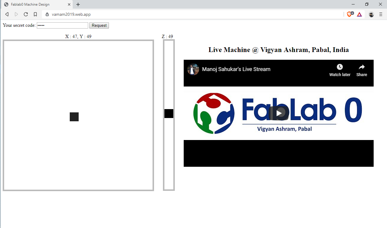
Link to control interface: https://vamam2019.web.app/
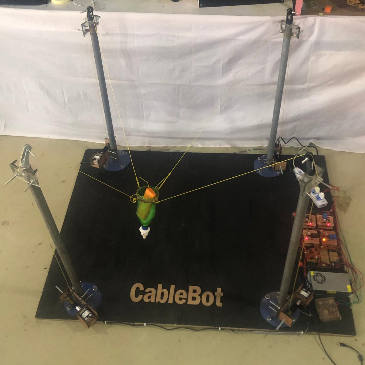
Cablebot Description:
Cablebot has been made with the vision to solve the challenges of farmers with large farms. Sowing seeds, watering and other activities on large field are challenging. Our model is the first step towards automation in farming using “Skycam” principle.
Cablebot Working:
We have used 4 cables to move the end effector. For every cable there is a stepper motor, winch and motor controllers in serial bus to achive the motion.
Individual Contribution:
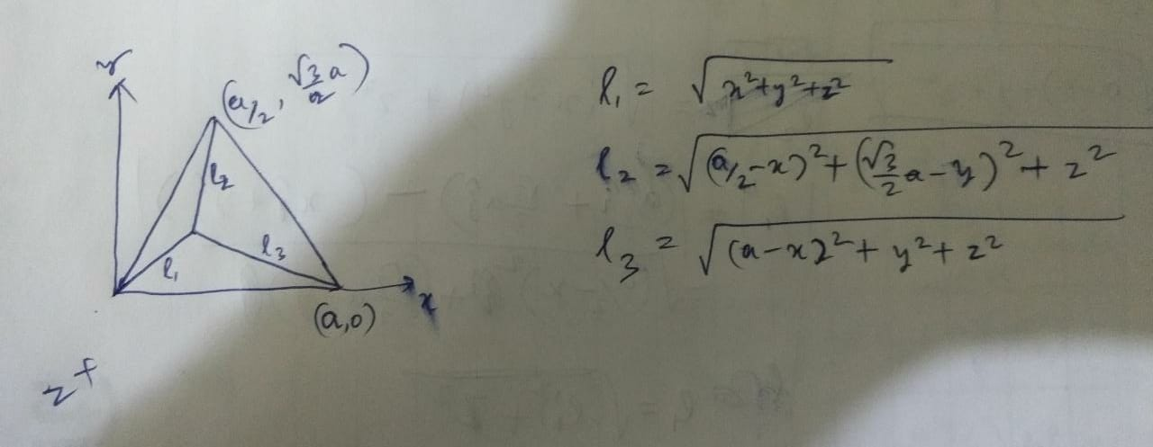
1. Winch Calculations:
A. Length of Winch:
a. Fleet Angle :The angle between the center line through the lead sheave and the centerline of the rope leading to the drum is called the fleet angle. Allowing a maximum 2° fleet angle the following calculations have been done-
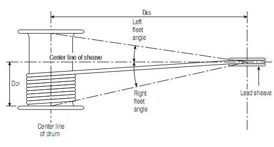
b. Length of Pole: The 4 ends have pole of the exact same length 91.4cm. Thus, Tan(2°) calculates the winch length:
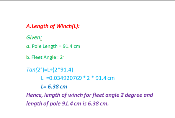
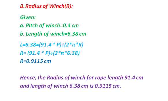
B. Diameter of Winch:
a. Pitch of Winch: in Fusion 360 we can define the pitch of winch which is 4mm in my design.
b. Length of winch: The value 6.38cm hs been calculated from above.
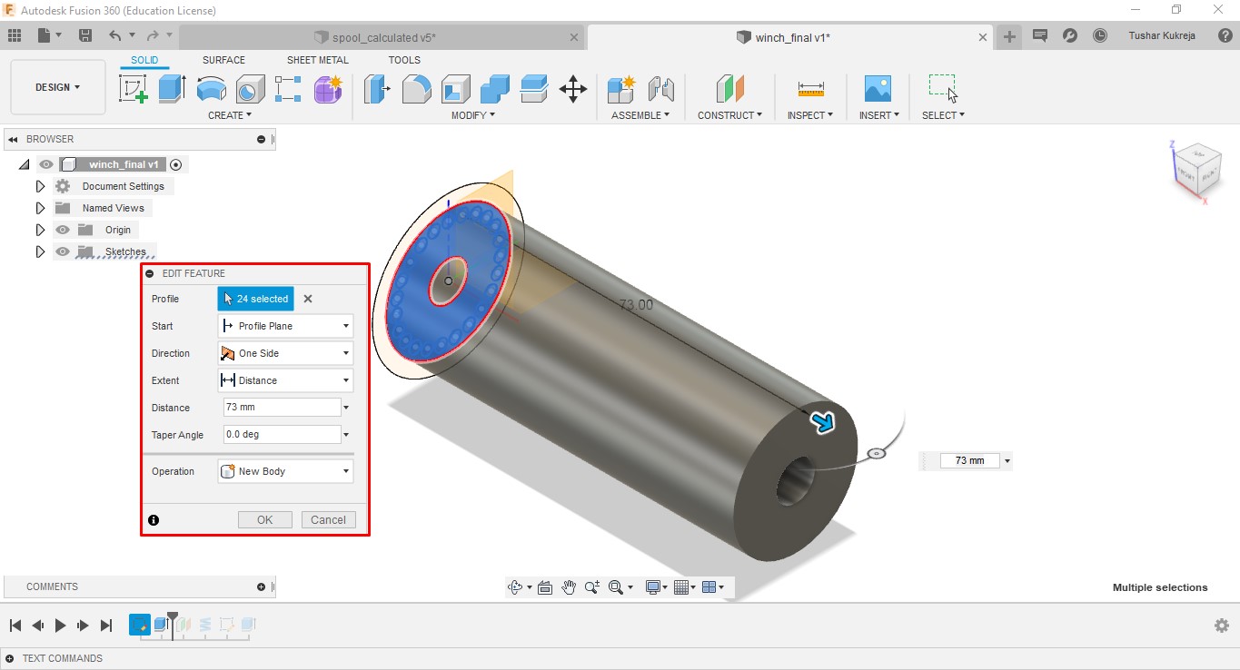
2.Winch Designing:
The gif below shows all the steps from sketch, extrude, construction plane and coil.
 A.Sketch: Create>Circle>Centre Diameter Circle. Made circle and also used circular pattern for the smallest cicrle.
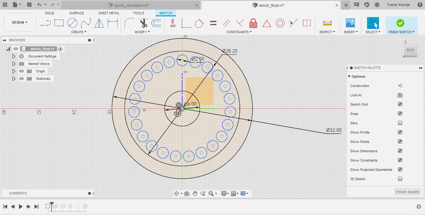
B.Extrude: The circle on extruding formed the cylinder shape of the winch.
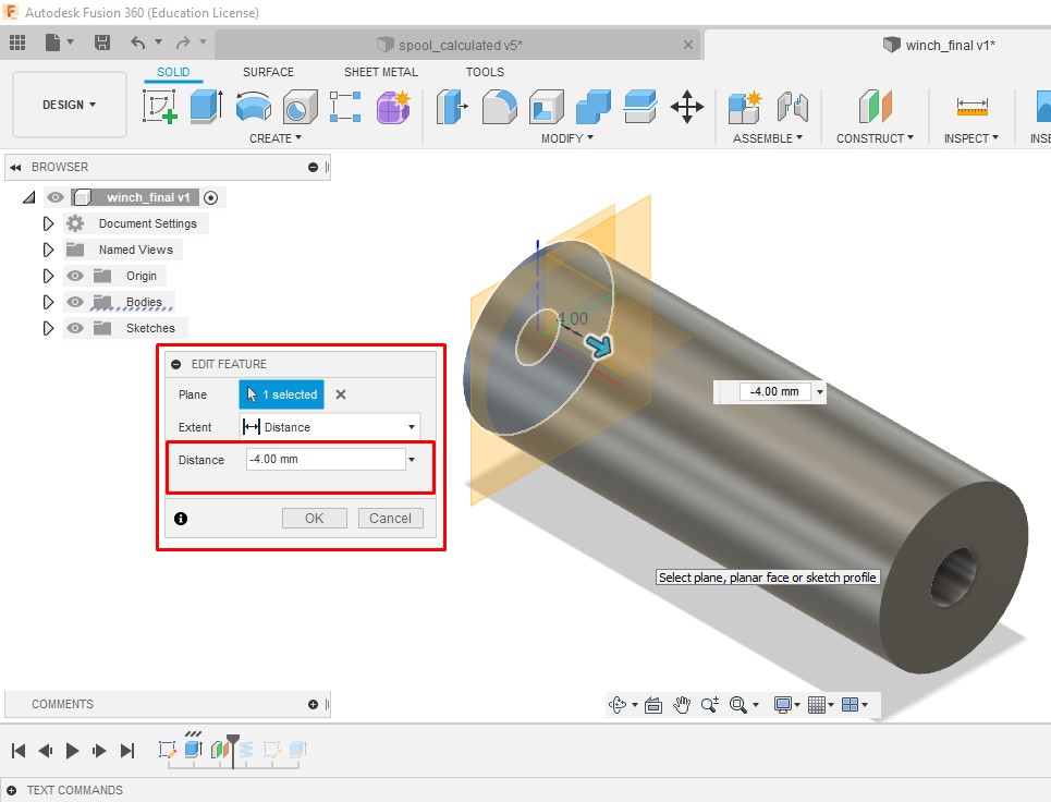
C.Construction Plane: Added a different plane 4 mm inside from the end. This marked the starting point of winch coil.
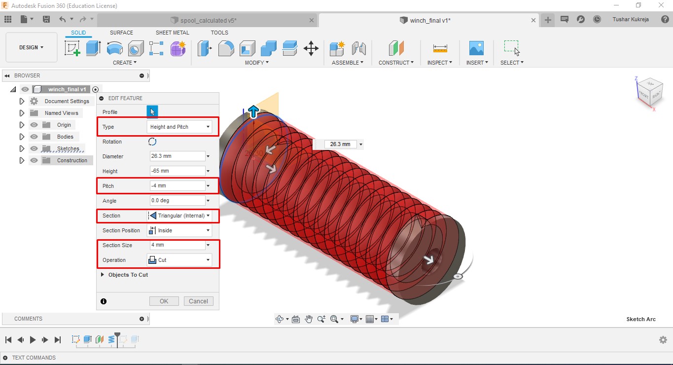
D. Coil: Entered diameter, height, pitch and Triangular(internal) coil of section 4mm. I also designed winch in circular and square coil type but 3D printer did the job best for internal triangular coil.
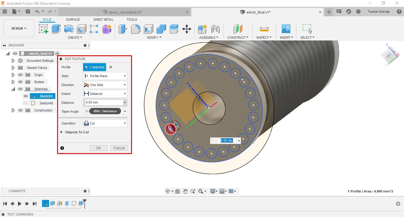
E. Extrude: Made a small hole on one end of the winch for the rope to be tied to.
3. Printing Winch on 3D Printer:
I repeated 3D printing by various coil types of square, circle and triangular. Also, experimented with printing it horizontally. With every print concluded to print it vertically, high quality print,triangular coil and removed the ends from the design to decrease the printng time.
4.Motor Selection:
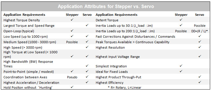
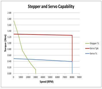
A.Servo vs Stepper: Compared motor type Servo vs Stepper on various application parameters. Majorily on parameters of speed, torque at various speeds and detent torque decided stepper motor would be the right choice for our CableBot.
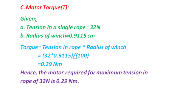
B.Calculations:Calculated the required torque of stepper motor on basis of tension in the rope and radius of the winch.
C.Purchase:On the following parameters,
a. Torque: of at least 0.3 Nm
b. Speed: high-speed motor not very necessary for the initial model of the machine.
c. Price: Under the permissible budget of the machine we were interested in motors of 1000 rs each.
We compiled lists of motors from various vendors comparing the specifications:
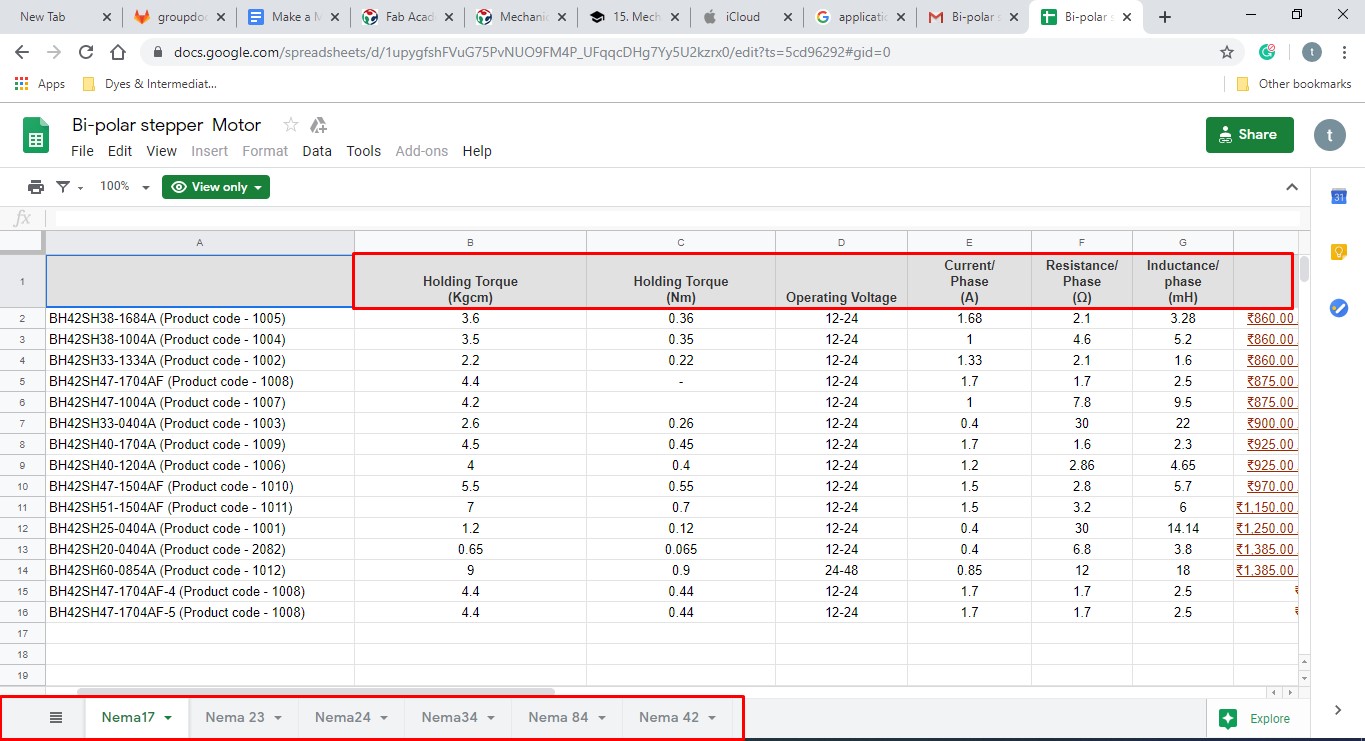
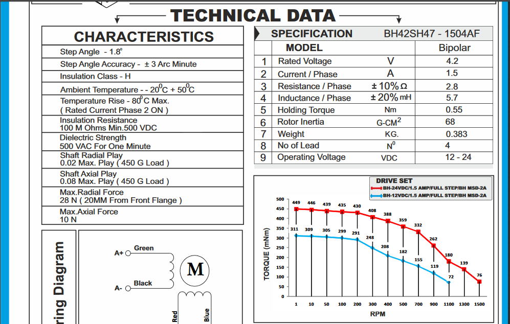
D.Nema-17:We finalized and purchased Nema-17, model- BH42 SH 47-1504 AF with following technical specificationsNema-17
E. Learnings: I thoroughly read about motors. The following are the important learnings.
a.Stepper motors generally are not available in frame sizes larger than NEMA 34, with most applications falling in the NEMA 17 or NEMA 23 motor sizes. As a result, it is unusual to find stepper motors capable of producing more than 1,000 to 2,000 ounce inches of torque.
b. Servo motor + Gear is also a good combination to achieve high speed and torque.
c. The combination of speed and torque enables servo motors to deliver better acceleration than stepper motors. They also deliver improved positioning accuracy as a result of closed-loop operation.
d. The motors that we will be using are D.C motors so we need SMPS.
e. Torque is also dependent on speed. The major torque types are:
1.Holding Torque
2.Detent Torque
3.Pullout Torque
f. Holding torque is one of the primary benefits that stepper motors offer versus servo motors, making stepper designs a good choice for cases where a load needs to be held in place.
g. A gear train will also increase the torque of the motor. Some tiny geared steppers are capable of impressive torque. But the tradeoff of course is speed. Geared stepper motors are generally limited to low RPM applications.
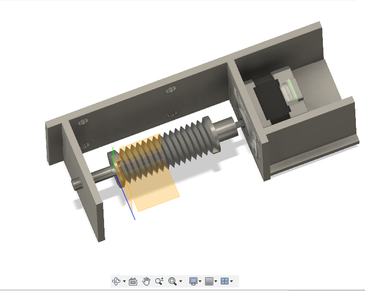
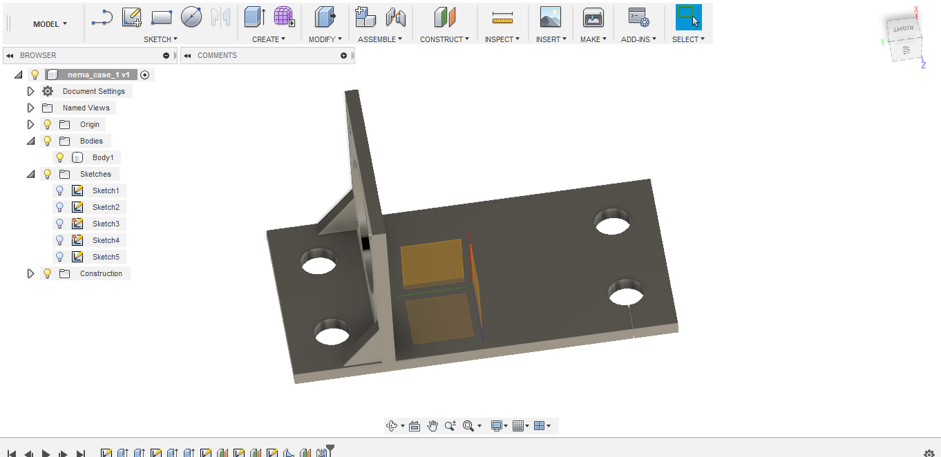
5.Nema17 Case Designing:
Designed the outer body to hold Nema17 motor. Assmebled the motor, winch and the outer body to see how well it fits.
A. Sketch: From the specifications of the motor, I got the dimensions of Nema17 motor. Accodingly, sketched the design with slots.
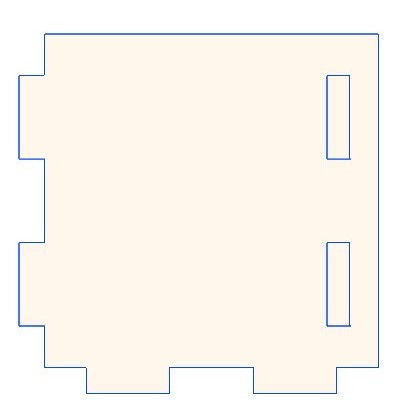
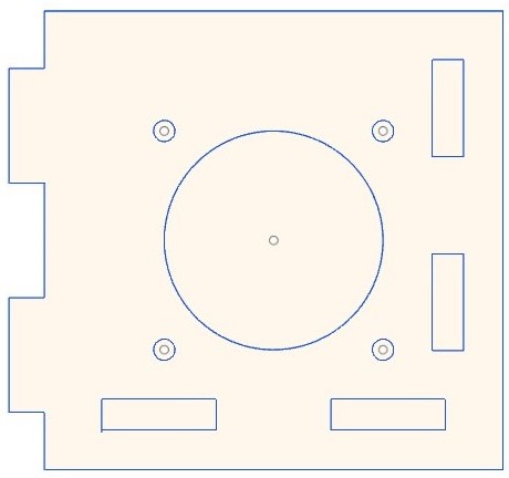
B. Extrude: Extruded the design 5mm since the case was to be built of 5mm plywood.
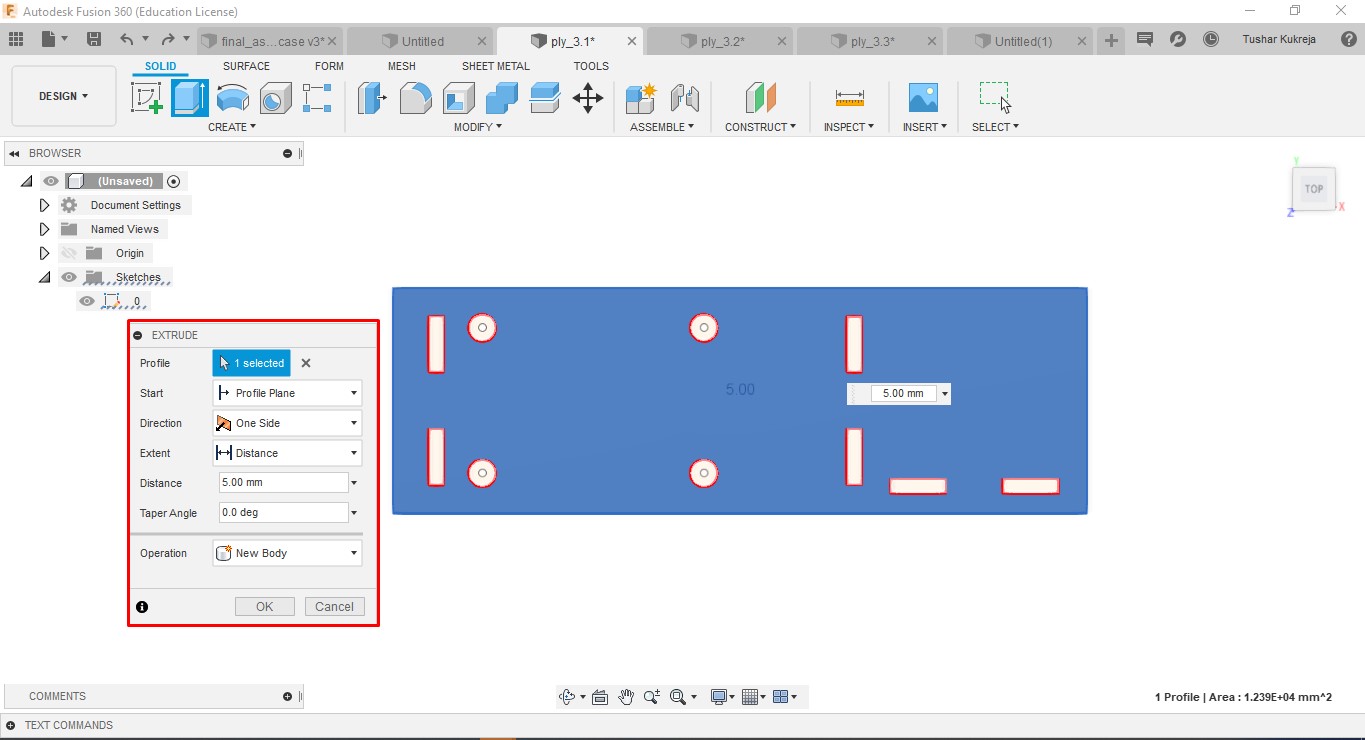
C. Body to Component: Converted the bodies to components so that I can join them. These individual compoents were saved in DXF format.
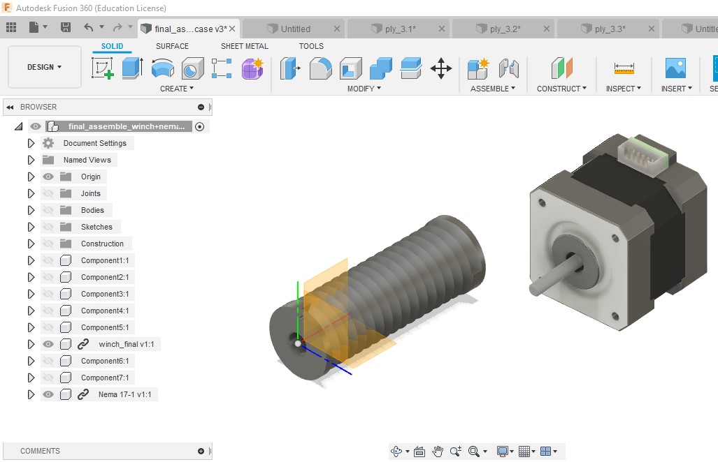
D. Insert: Thw winch designed and Nema17 was imported in the same design to be joined at various points to see the final assmebly.
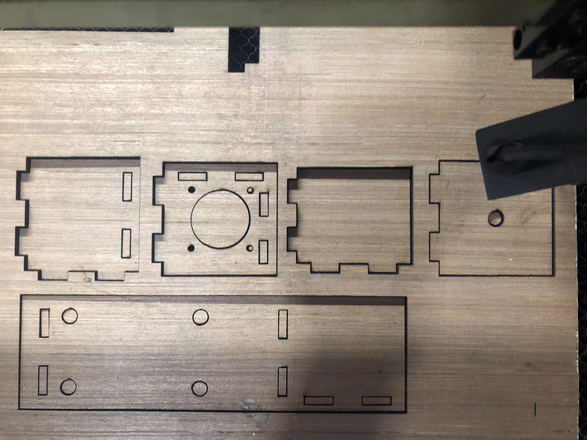
6.Nema 17 Case Laser Cut:
Laser cut the plywood of 5mm which has slots for the assmebly to press-fit.
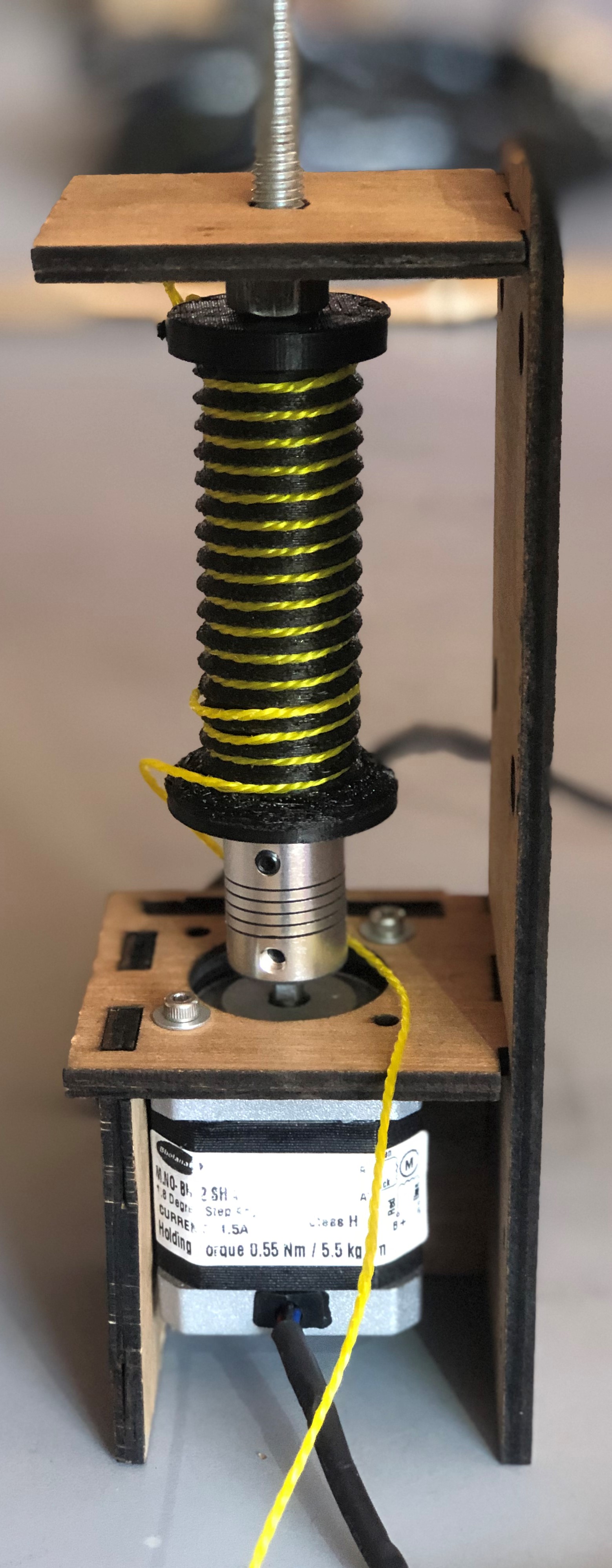
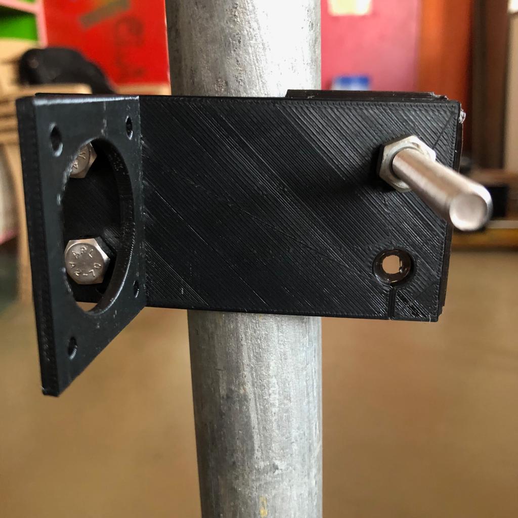
7. Assmebly:
The picture below sums up my entire cntribution from selcting motor, designing and 3D printing winch and outer body design and laser cut. This was set up to all the poles at the 4 ends.
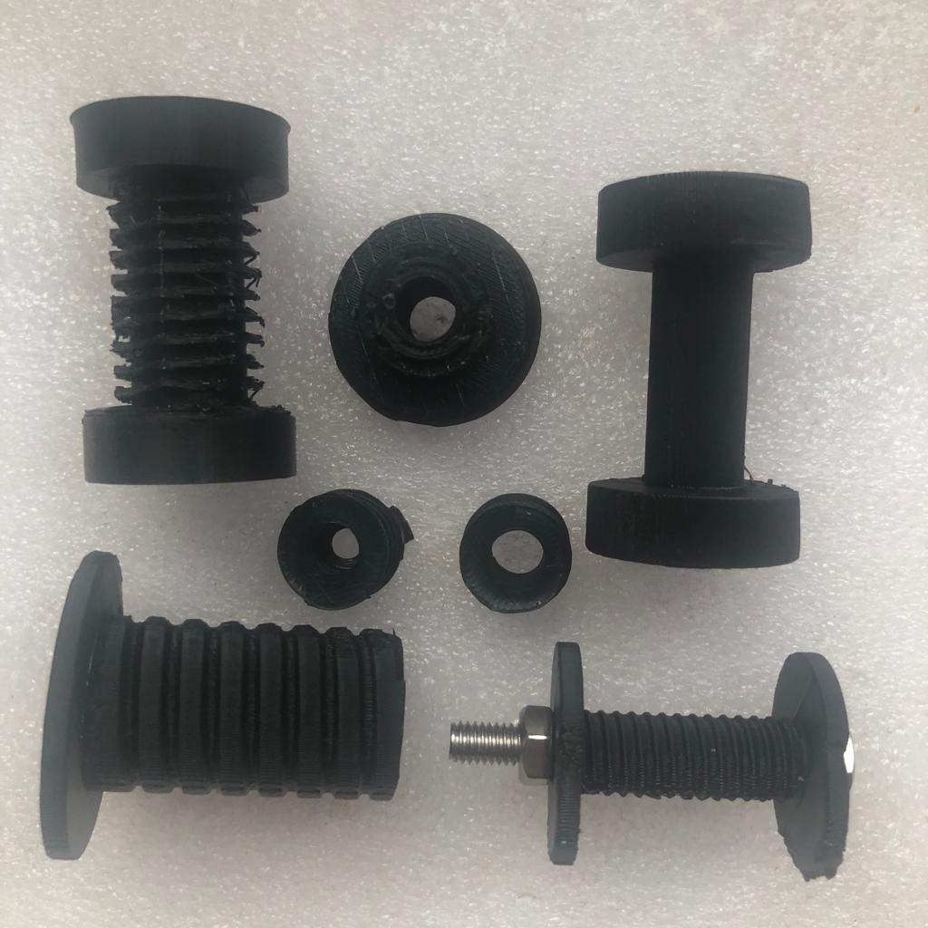
8. Failures:
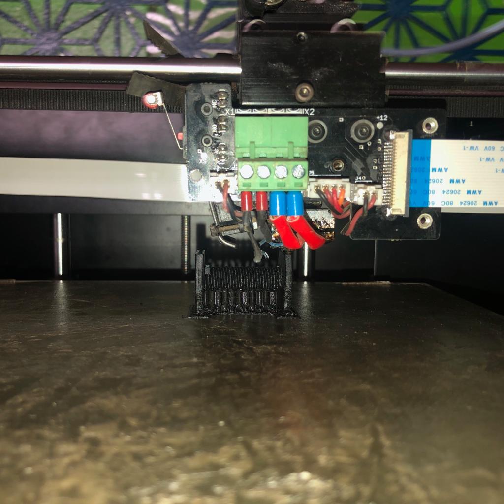
1. Printing Iterations: I had to try many iterations of printing winch because 3D printed didnot print the coil type or the pitch properly. Changed orientation, print quality and bed settings. The picture below shows the failed attempts-
2. Nema-17 Motor Case: The first case was 3D printed after designing in Fusion 360. But 3D printer took lot of time and requirement of Nema-17 case was at all 4 ends. So, I shifted to laser cut
Winch design files are available here
Nema17 case design files are available here
Group Contribution
The group page has the entire content of Mechanical and Machine design.
1. Mechanism
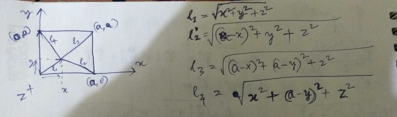
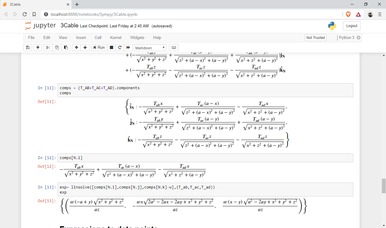
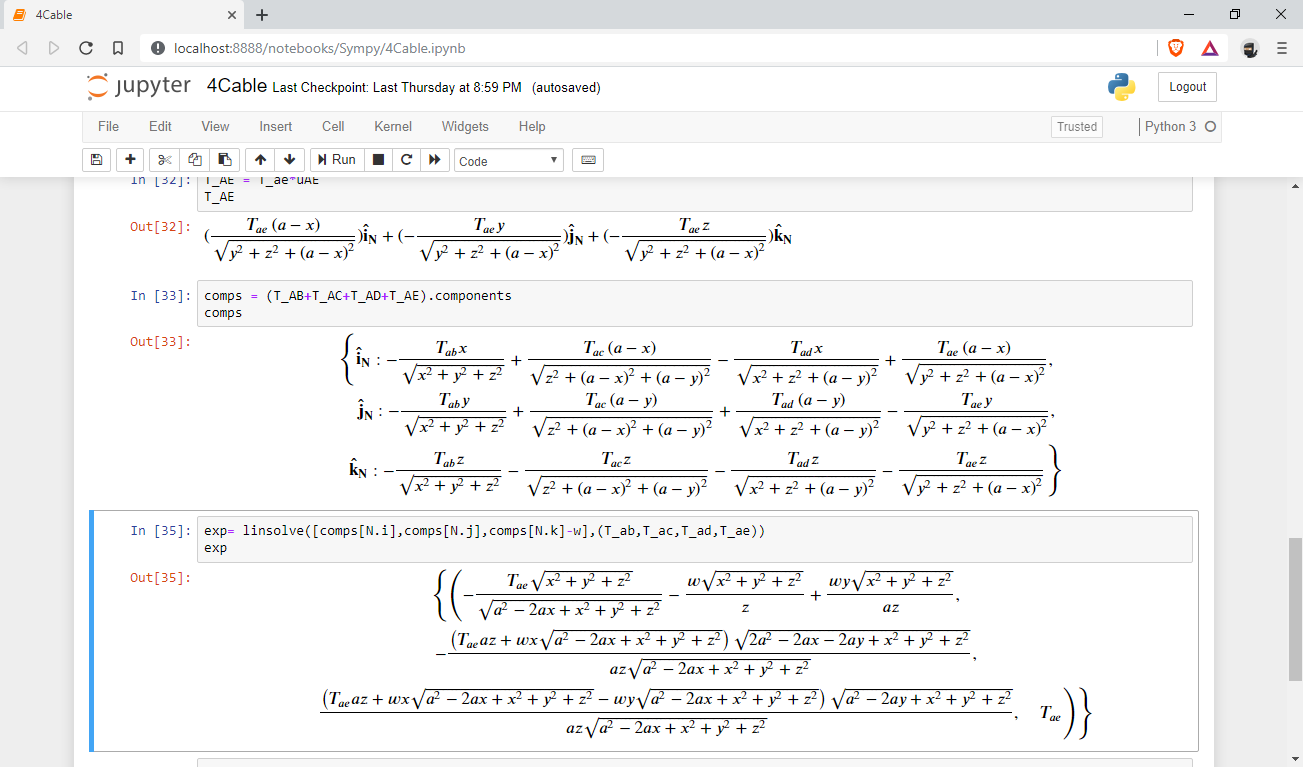
Manoj did the math to determine the cable length as well as cable tension at given X,Y,Z. This was used in control system and stepper motor selection for actuation.
2. Actuation
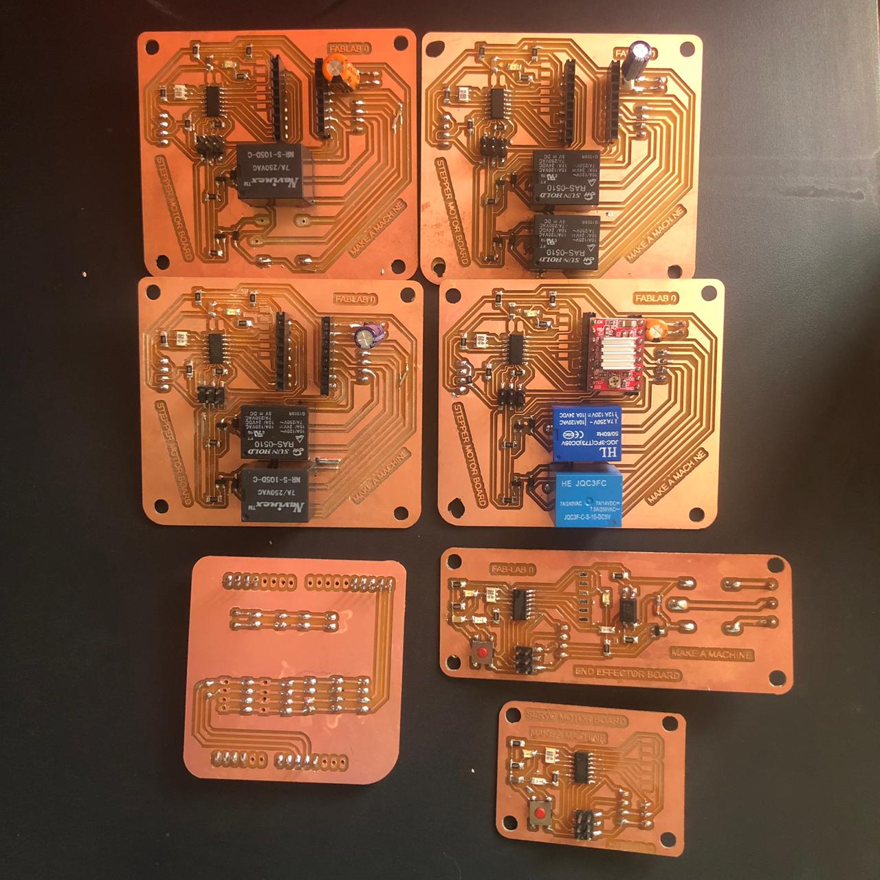
Manoj, Jayadip and Aditi we’re involved in board design, fabrication and troubleshooting. We decided to divide the slave part in 4 design.
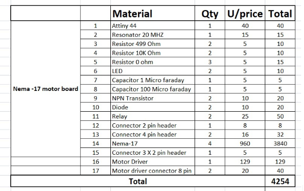
1.Design for Nema-17 motor board -4 nos.(for 4 pole each)
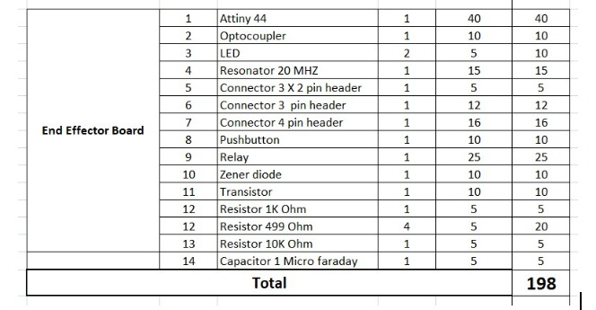
2.End effector board -1 No.
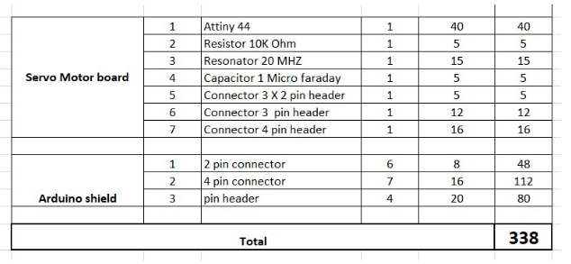
3.Servo motor board-1 No.
4.Shield for Arduino
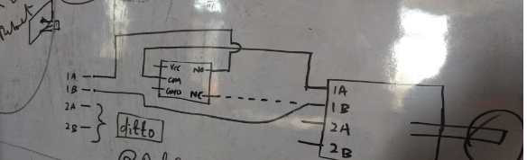
For electronic part of nema -17 motor board we referred this tutorial(by how to mechatronics) We used magnetic lock by shorting the coils to lock the end-effector position during power off mode. It is necessary as the end effector is hanging.
The BOM for all the boards:
3. Application Interface and Control System
Manoj wanted to making a version of Distributed Dataflow Machine Controllers. He used firmata in Arduino to setup a master-board along with johnny-five to program the virtual machine in Javascript. He the along with his sub-groupmates made stepper motor driver boards which consist of ‘A4988 driver along with attiny44 MCU’ as I2C slave boards. He used wire library for communication.
He developed this control interface using (jQuery-Kontrol)[“https://github.com/aterrien/jQuery-Kontrol”] and firebase’s realtime database ‘Cloud firestore’.
4. Final Video and link to the interface:
Link to control interface: https://vamam2019.web.app/
Refrences
1.Amazon nema-17 motor
2.Cable Robot
3.Low Cost Cable Robot
4.Stepper Motor Torque Basics
5.What’s the differnce between Servo and Stepper motor
6.Zikodrive Motors
7.Torque Holding