8. Computer controlled machining
Highlights of the week:
At Vigyan Ashram we have plasma cutter and laythe machine but for making somthing big we need CNC milling machine.We went to COEP college and Muktangan Science lab, Pune. The college has CNC shopbot wood Router and Muktangan lab has Indian manufactured CNC machine.
Group Assignment:
CNC Machining:
Computer Numeric Control, CNC Machining is a process used in the manufacturing sector that involves the use of computers to control machine tools. Tools that can be controlled in this manner include lathes, mills, routers and grinders.
Types of CNC Machines:
1. CNC Mills:The programming employed for a mill machine could be based on either G-code or some unique language developed by a manufacturing team. Basic mills consist of a three-axis system (X, Y and Z), though most newer mills can accommodate three additional axes.
2. Lathes:In lathe machines, pieces are cut in a circular direction with indexable tools. With CNC technology, the cuts employed by lathes are carried out with precision and high velocity. CNC lathes are used to produce complex designs that wouldn’t be possible on manually run versions of the machine. Overall, the control functions of CNC-run mills and lathes are similar. As with the former, lathes can be directed by G-code or unique proprietary code. However, most CNC lathes consist of two axes — X and Z.
3. Plasma Cutters:In a plasma cutter, material is cut with a plasma torch. The process is foremost applied to metal materials but can also be employed on other surfaces. In order to produce the speed and heat necessary to cut metal, plasma is generated through a combination of compressed-air gas and electrical arcs.
4. Electric Discharge Machines:Electric discharge machining (EDM), alternately referred to as die sinking and spark machining, is a process that molds work pieces into particular shapes with electrical sparks. With EDM, current discharges occur between two electrodes, and this removes sections of a given work piece.
5. Water Jet Cutters:In CNC machining, water jets are tools that cut hard materials such as granite and metal with high-pressure water. In some cases, the water is mixed with sand or some other strong substance. Factory machine parts are often shaped through this process.
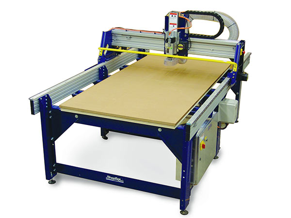
ShopBot CNC Wood Router:
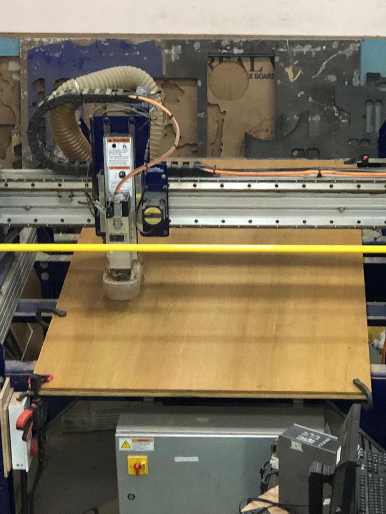
The ShopBot PRS Alpha is a CNC machine that allows users to cut, drill, carve and machine wood, plastic, aluminum and other materials along 3 axes, X, Y, & Z. With enough production capability of manufacturing, ShopBot PRSalpha tools are tough and gantry-based CNC routers.
1. Specifications of Shopbot: 
A. Sheet Material upto Size: 4’x 8’ with machining depth (Z axis) of 6 inches.
B. Table Size: 6’x 10’
C. Step Resolution: 0.0005’ or better depending on the gear ratio
D. Positioning Accuracy: +/-0.0005” or better(No load)
E. Positioning Repeatability: +/-0.003” or better(No load)
F. Cutting Accuracy:+/-0.015” or better for heavy cutting applications
G. Simultaneous Linear Interpolation:3 dimensional
H. X,Y Cutting MOvement Speed:240”(standard)/600(Alpha) per minute
I. X,Y Rapid Positioning Speed: 600”(standard)/1800”(Alpha) per minute
J. Z Axis Move Speed:360” per minute
K. Linear Force:60-75(standard)/150-200(Alpha)lb. at 60° per minute, depending on gearing.
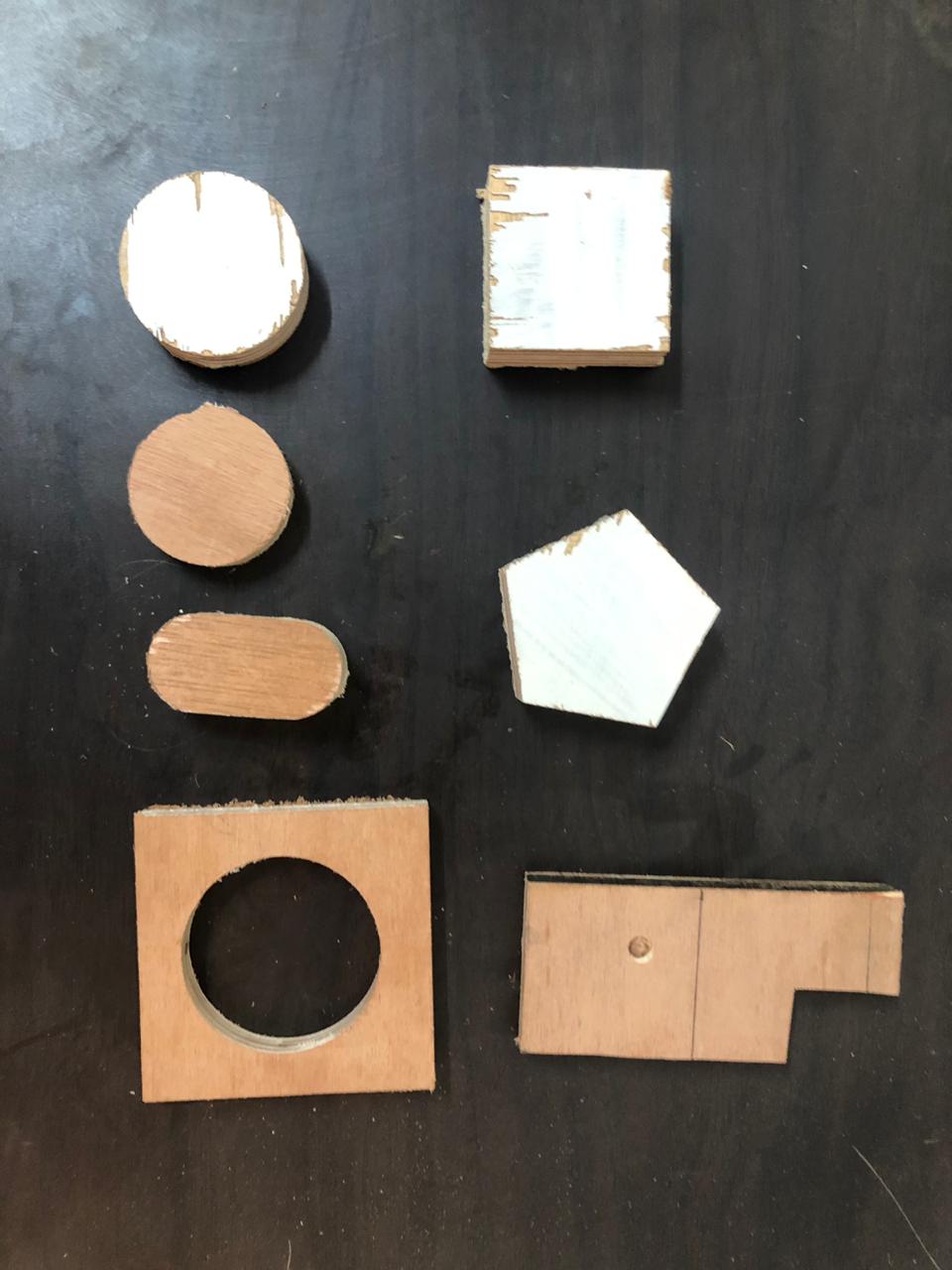
2. Test Parts on ShopBot:
A. Design and toolpath on PartWorks: On PartWorks chose the bed size as 2400 x1200mm and drew basic test parts circle, square, pentagon etc.Generated toolpath and under edit options we set the parameters.
B. Settings and Parameters:
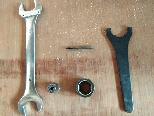
a.End Mill: We used bit size 1/4” for cutting.
b.Plunge Rate:It is also known as stepdown. The distance in the z direction per pass that a cutting tool is plunged into the material.
c.Spindle Speed :Rotational speed of the cutting tool in revolutions per min.
d.Step Over:the maximum distance in the x/y direction that a cutting tool will engage with uncut material.
e.Feed Rate:Surface speed at the center of the Rotating tool.
f.ShopBot3 editor:Opened the editor and using the keyboard keys adjusted the X,Y,Z position.
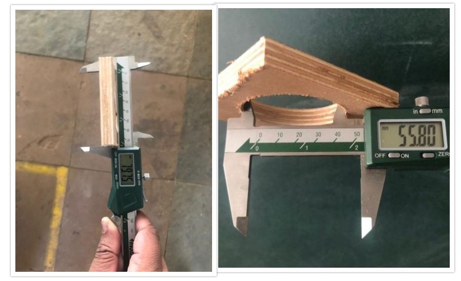
C. Test parts: After bed setting, instructed the machine to cut the test parts. We also measured the “Kerf” values for the test parts.
Individual Assignment:
1. Design
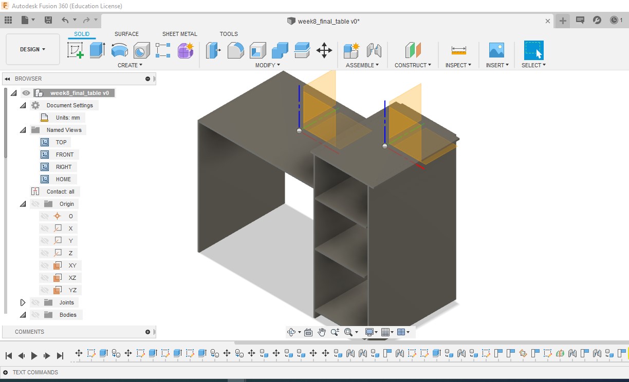
Being a beginner it was very difficult for me to design a table. My approach was to make a 3D table in Fusion 360 and then convert every single part into DXF for cutting. This gave me the idea how table would look after assembling all the parts.
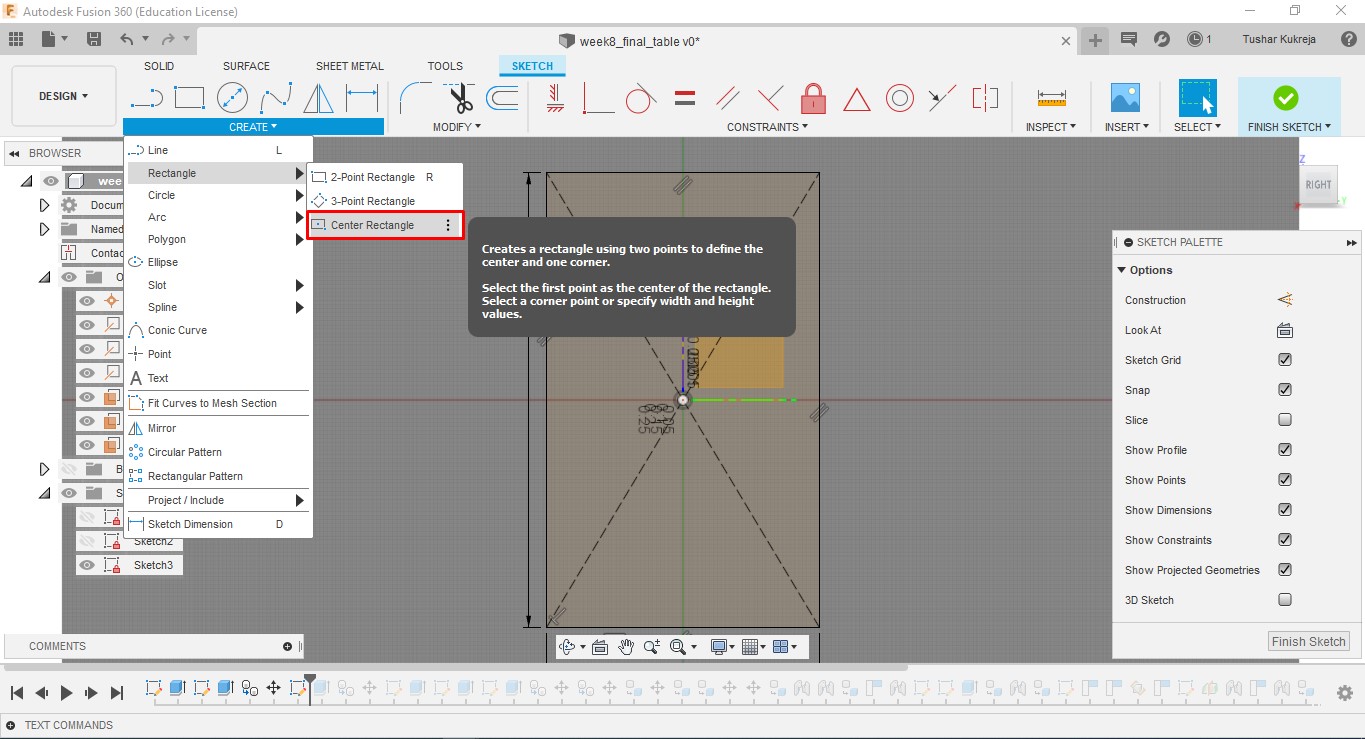
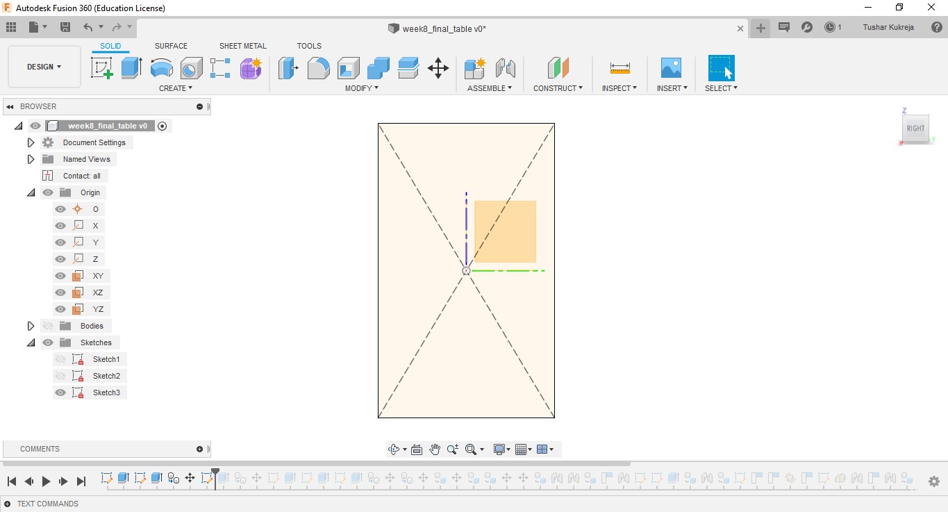
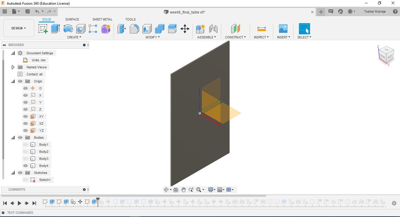
A.Sketch:Create>Rectangle>Centre Rectangle made 2D shapes mostly reactangles of various sizes for the table. Further made slots for every part to fit into one another.
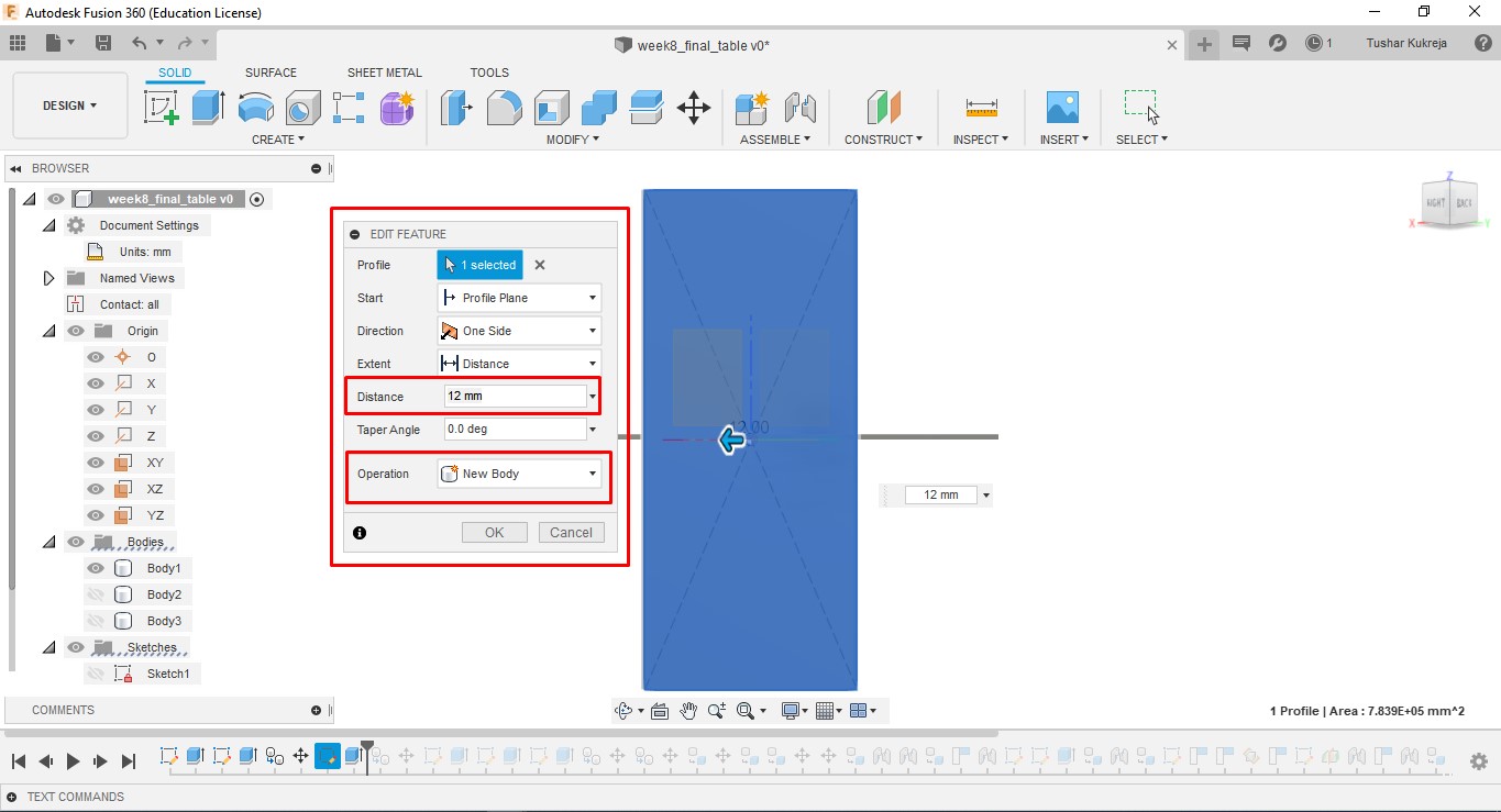
B.Extrude: I have used 12mm plywood and 15mm MDF for table. Gave the extrusion width accorindly.
C.Body to Component: Converted the bodies to components so that I can join them. These individual compoents were saved in DXF format.
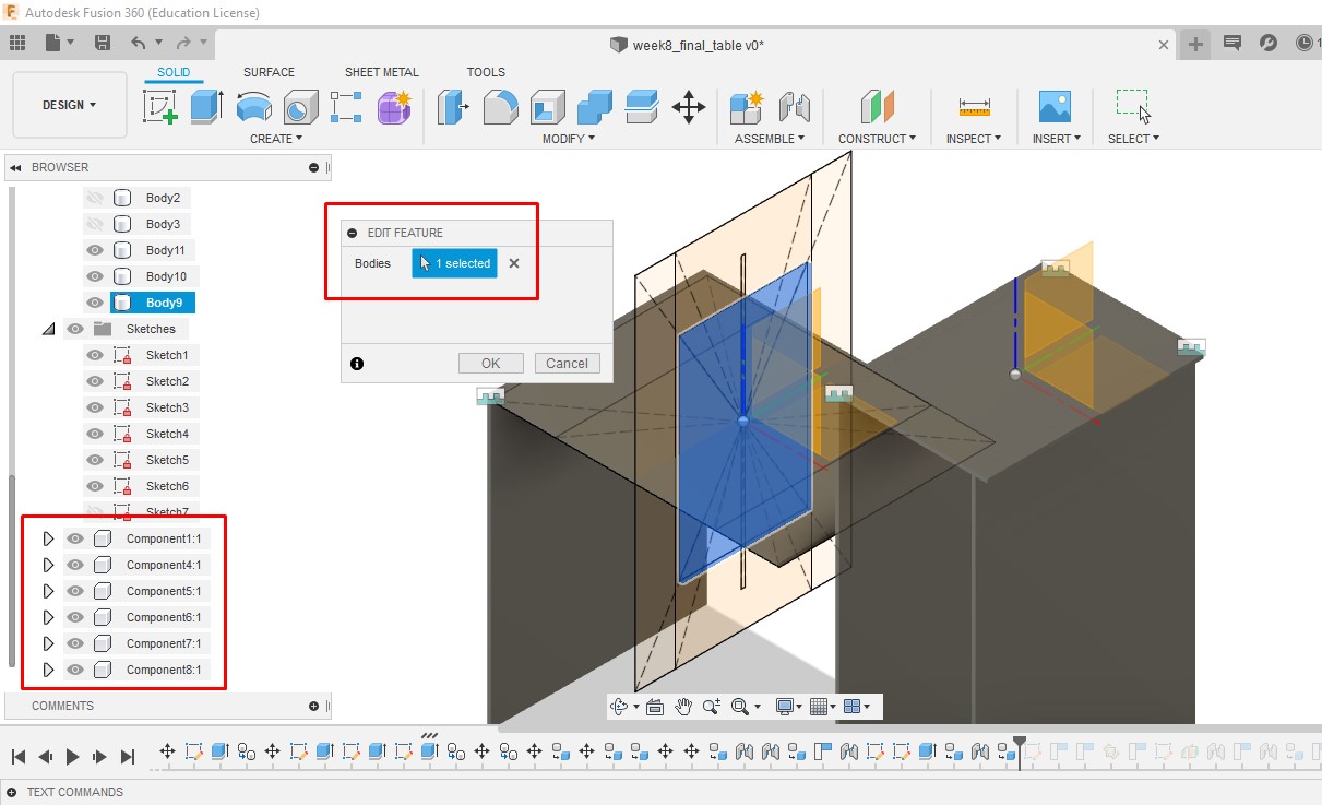
D. Joint: Selected the components to be joined by Rigid Motion. Importantly, the component to be moved is to be selected as 2nd component. 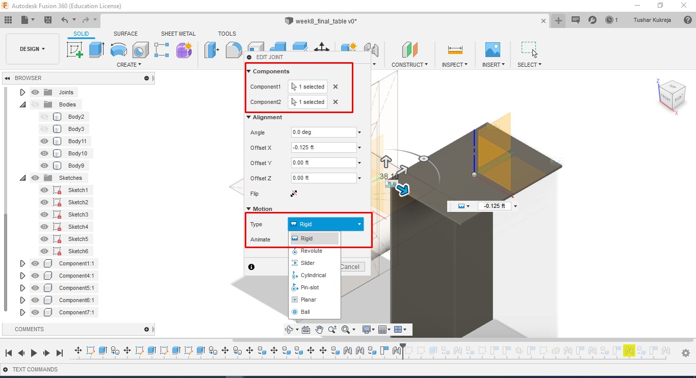
I tried using Dogbone joint. But the challenge I face was to make Dogbone feature manually at every joint. I understood there is no specific feature as “Dogbone” in Fusion 360. Being a fresher in desiging and to finish the assignemnt in a week was a challenge. So, I normally had pressfit parts to fit into space with one another.
2.PartWorks
PartWorks is the software used for making toolpaths and sending Gcode to CNC Shopbot wood cutter.
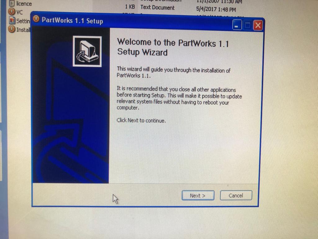
A. Insalled PartWorks: There was some issue with the software PartWorks, it had to be installed everytime we started the system.
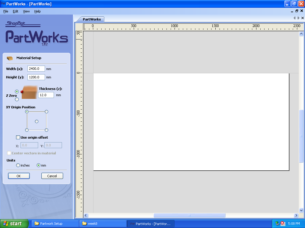
B.New File and Material Setup: Opened new file and updated “Width(x)=2400mm” and “Height(y)=1200mm” and thickness of material i.e, “plywood 12mm”.
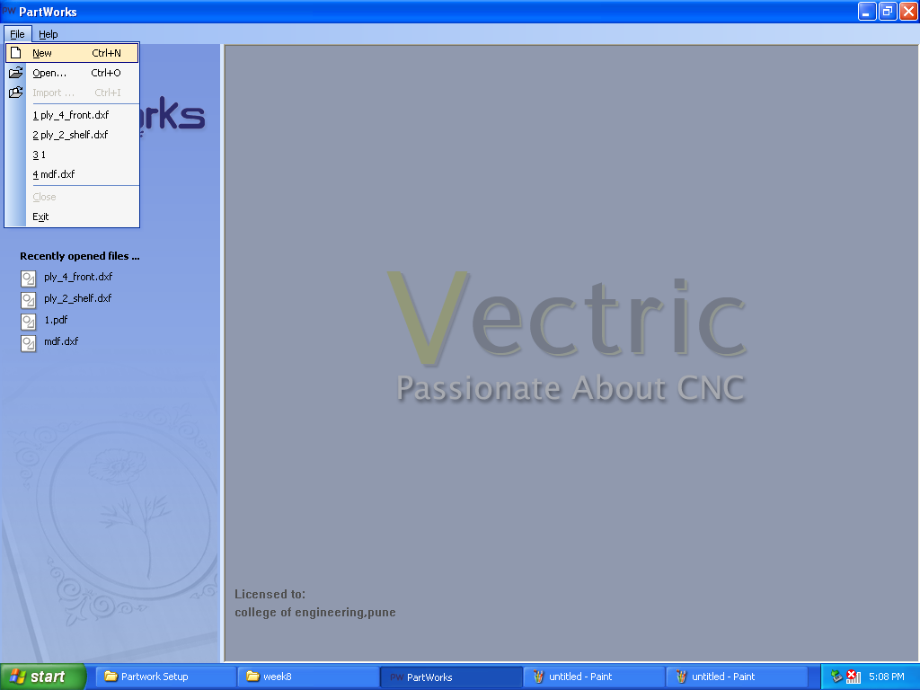
C. Import: File>Import Opened file designs in .dxf format and arranged them in the bed size selected above step.
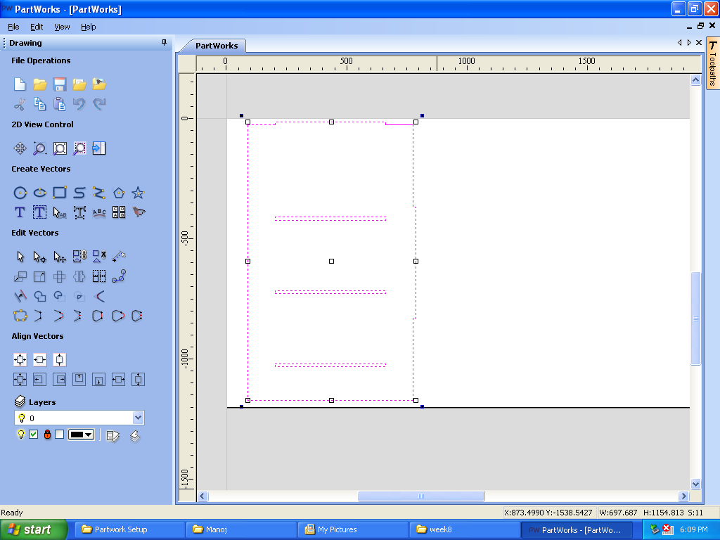
D. Create Profile Toolpath:After joining vectors, selected crete profile toolpath and adjusted Start Depth(D)”0mm” and Cut Depth(C) to “13mm” for 12mm plywood.
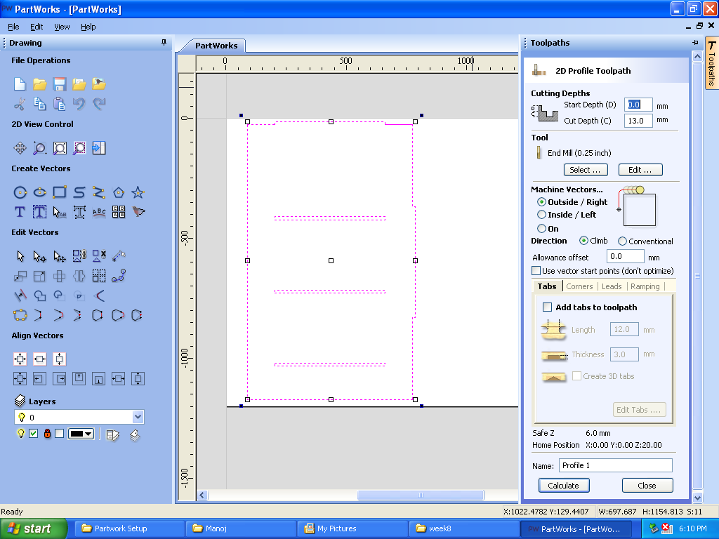
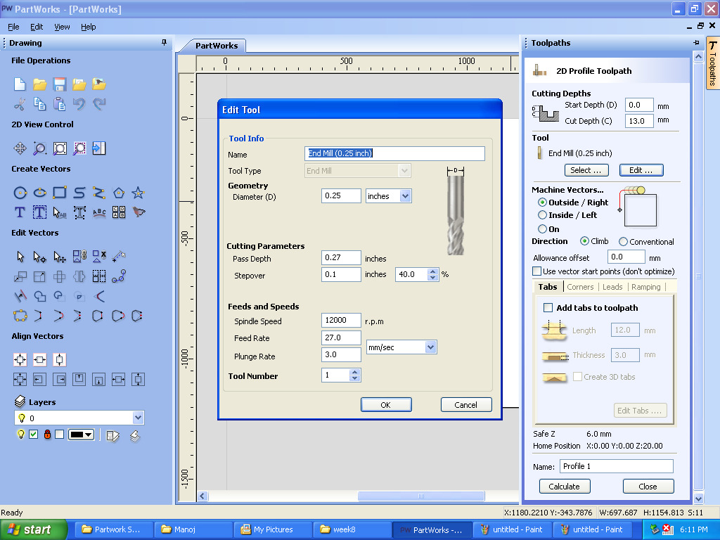
E. Edited end mill parameters:
a. Diameter of endmill:0.25 inches
b. Pass Depth:0.27 inches
c. Stepover:0.1 inches
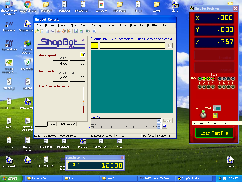
d. Spindle Speed:12000 rpm
e. Feed Rate: 27mm/sec
f. Plung Rate: 3mm/sec

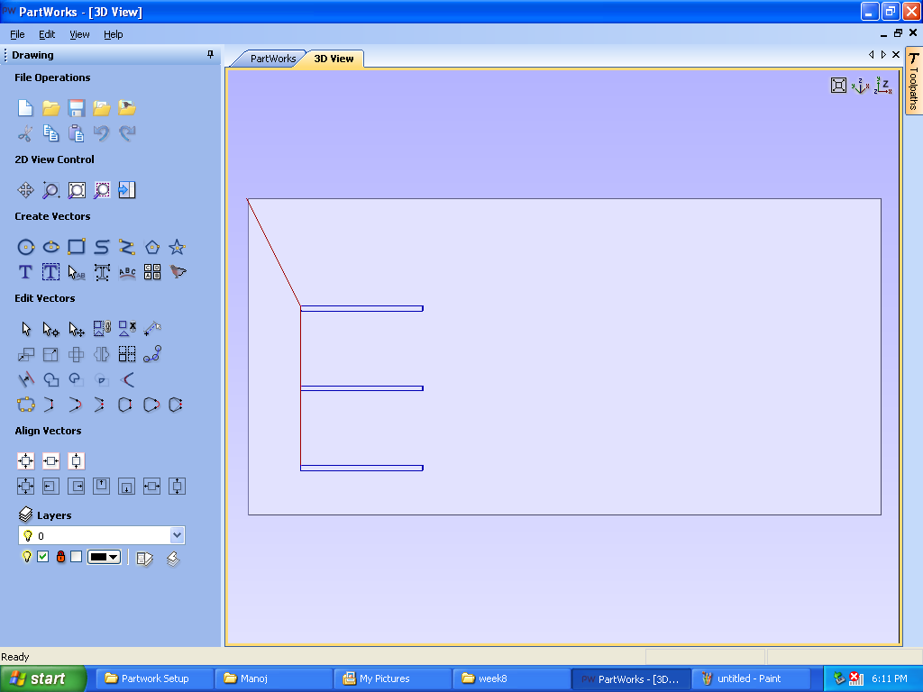
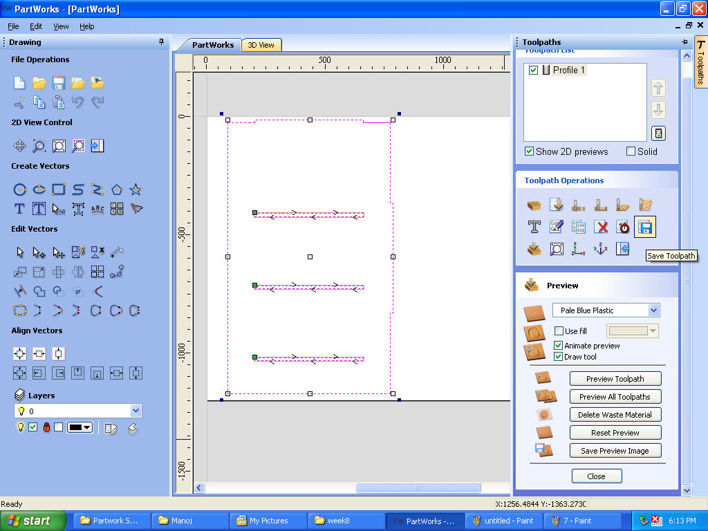
F. Calculated Toolpath: It shows the direction in which end mill will move to cut the plywood.
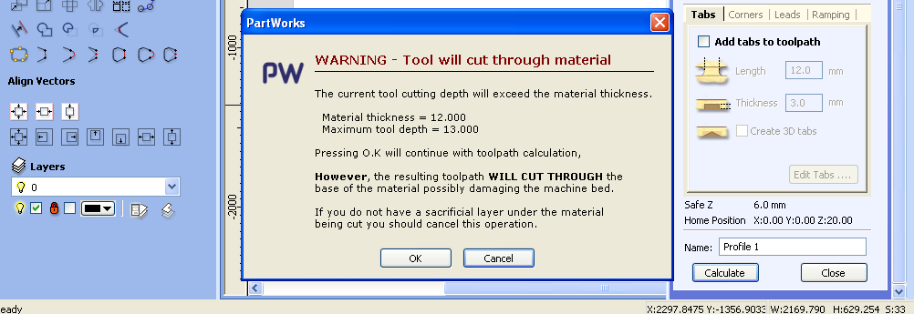
G.Warning: The warning on the screen is because we have adjusted material thickness 12mm but cut depth 13mm Pressed “ok” and moved ahead.
3. Milling:
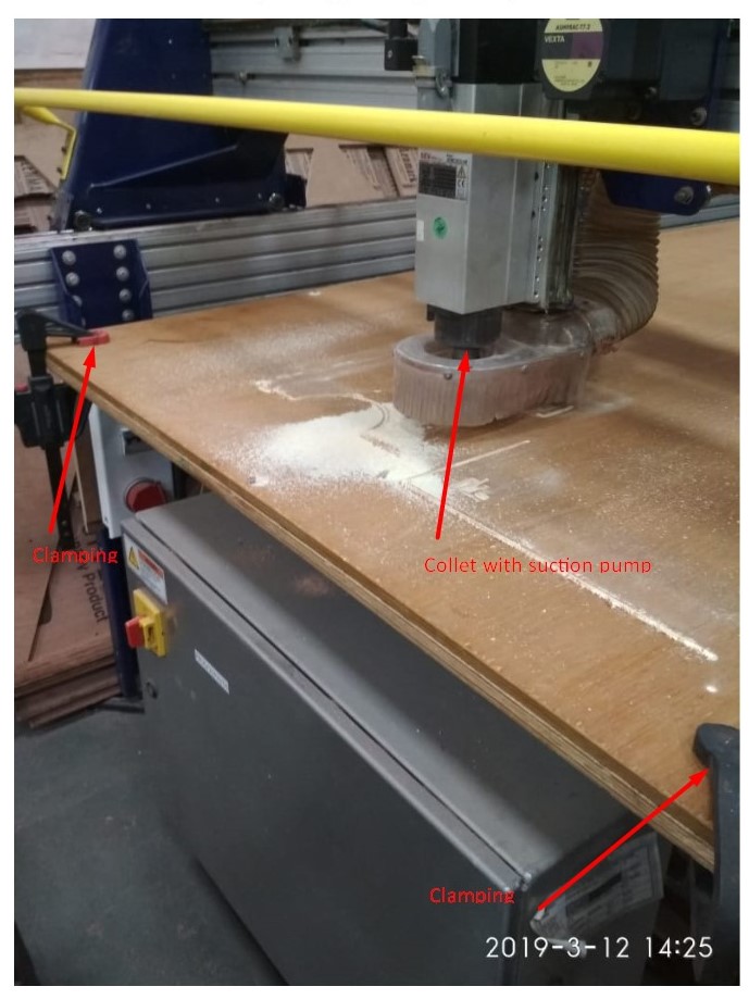
A. Plywood/MDF Sheet: Placed plywood or MDF sheet oon the sacrifical layer. Shopbot machines bed made up of metal and to protect this bed we place flat layer of the plywood on the metal bed which is the sacrificial layer. In case the endmills plunges more than the thickness of the material it will cut into the sacrificial layer hence this extra layer is important.
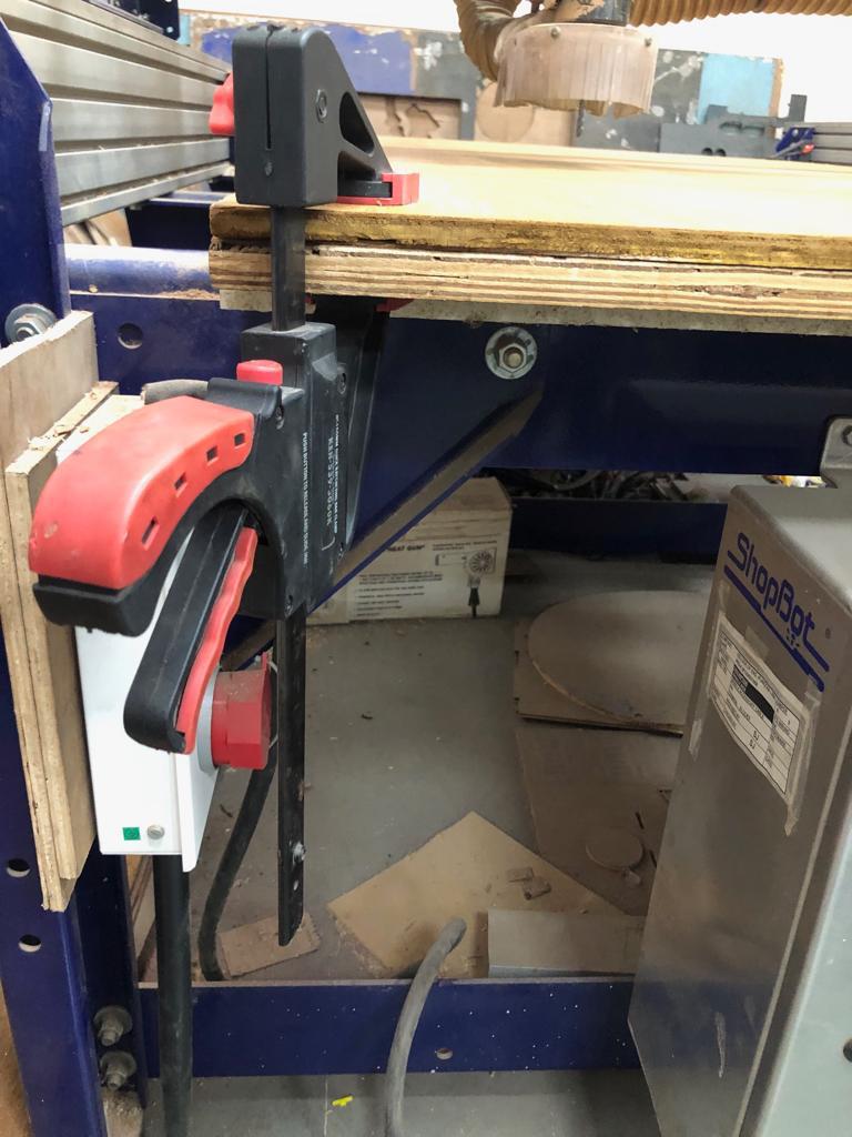
 B. Clamp: Fixed clmaps at the corners to keep the MDF/plywood sheet straight.There should not be gap between sacrifical layer and the material.
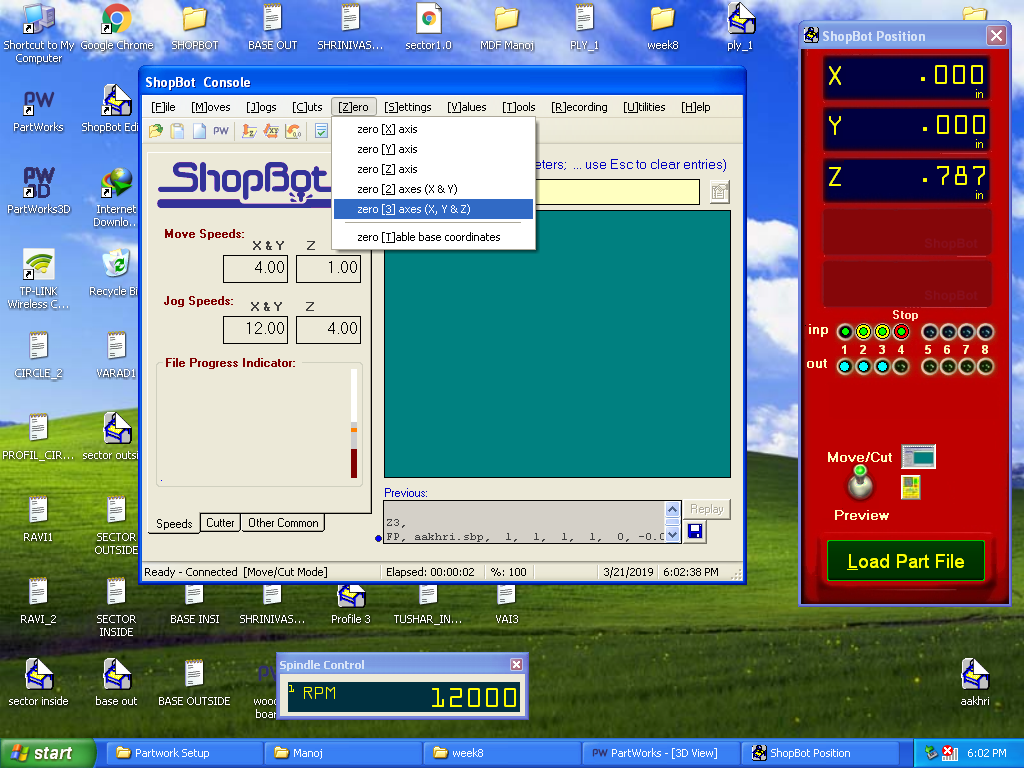
 C. ShopBot Console: Opened the ShopBot position and ShopBot Console to load part file which has tool path created on PartWorks.
D. ShopBot Keypad: Changed the direction of key 1,2 and 3 on Shopbot Keypad so that the endmill position can be changed from the keyboard.
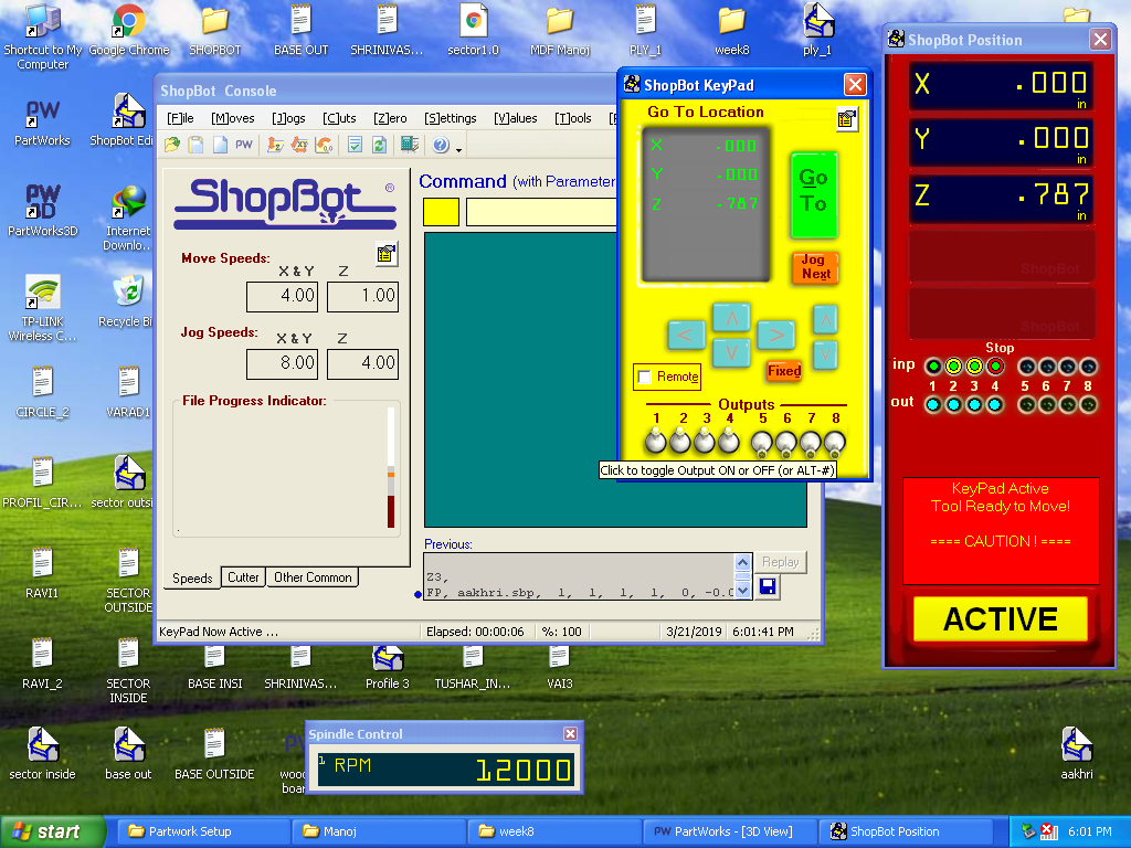
E. Origin Positioned the endmill considering the size of the object to be cut. zero[3] axes(X,Y&Z) on ShopBot console marked the position of endmill as (0,0,0)
G. Milling: It was extremelly noisy while end mill went through plywood to cut the parts. We wore noise blocker headphones. The dust created while cutting was sucked by vaccum and collected in a vessel behind the machine. []
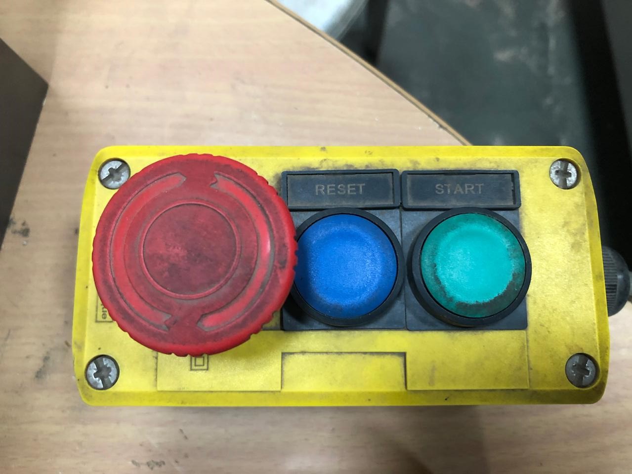
H.External Control: To stop the machine in case of emergency,reset or start external 3 buttons are handy.
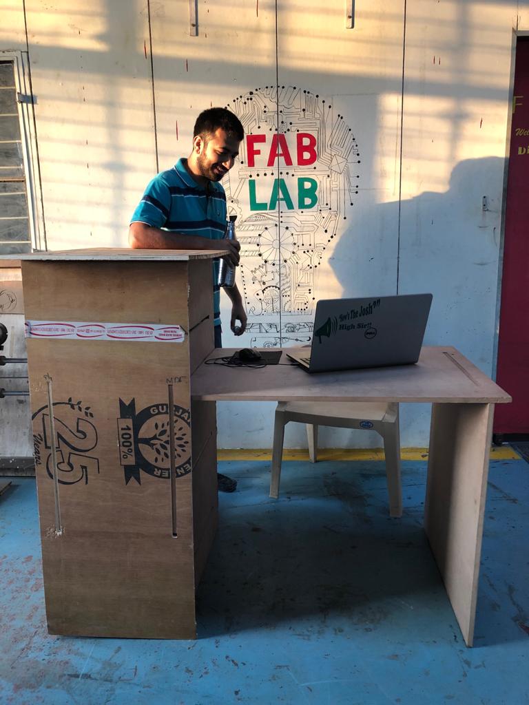
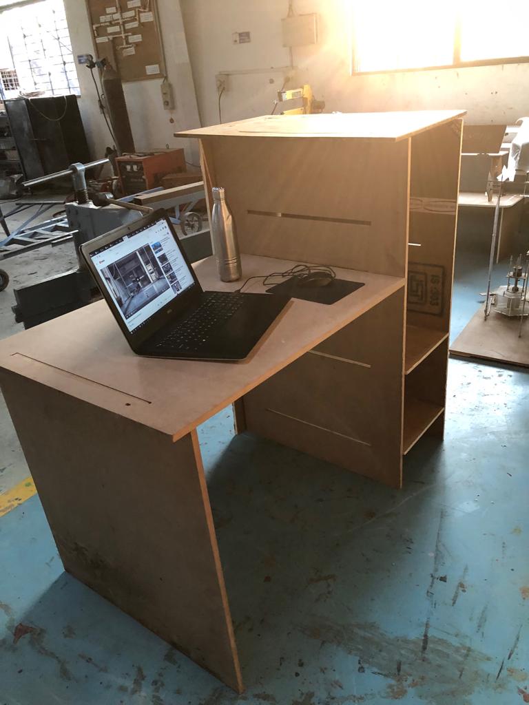
4. Assembly:
My study table was ready. It was such extremely satisfactory moment and I recieved appreciation for the work. The table parts fit into each other in the notches. Used Rubber hammer to fit the parts together. Here, I learned the importance of interlocks and joints. If I had used some joint where additional interior corner cuts for connecting parts, the interlocks would have been much better.
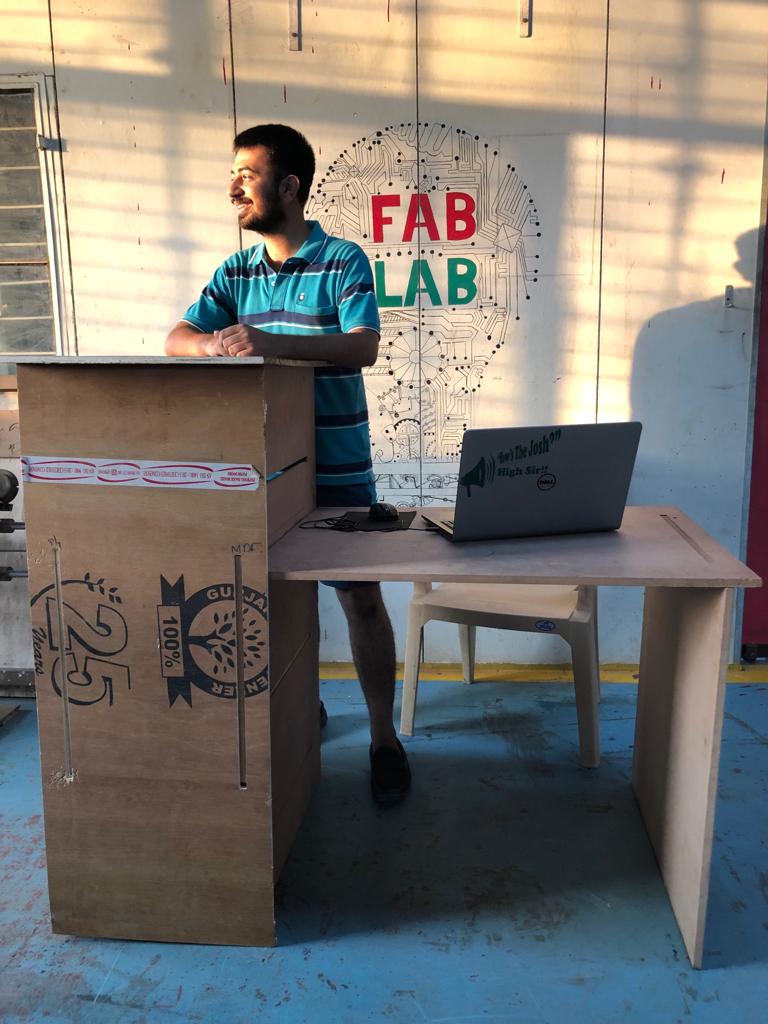
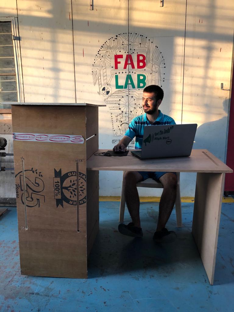
After assmebling, I am using my study table in my room. I have realised Ergonomics importance,the scientific discipline concerned with the understanding of interactions among humans and other elements of a system. I feel the corners should be blunt and the table needs to be polished to increase durability and aesthetic look.
Problems Faced:
-
I faced problem with Partworks software. Everytime Shopbot machine had to be used had to install “Partworks” software. The trouble was with the outdated local system. The instructor explained they used an old windows version and needed a better dekstop.
-
All the data from my pendrive was erased when I connected it to the ShopBot desktop. I got tensed but fortunately one of my friends helped me recovering it back. Again the desktop used for “Partworks” and “Shopbot” had some virus.