Week 17: Machine Design
05/21/2019 - Stéphane Muller
This week we have to automate and actuate the machine we started building during week 15.
Picking things up where we left off, we now need to make boards controlling each of our parts and have them communicate with each other. So the first thing we needed to do was brainstorm and get on the same page as to how the whole system and network will work. Here is the result of our session!
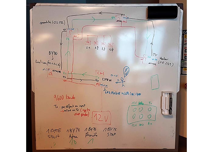
So we agreed on having one master board and slave boards for each part of the system. The master board will be powered by an ESP8266 and linked to a webserver. The slave boards will be powered by ATTinys and everything will be connected to a serial bus. The bus will carry 12V, ground, Tx and Rx lines.
Communication will happen over 4 bytes: a start byte, the destination node ID, the parameter and the stop byte.
Planning and list of tasks
- Designing the board
- Making the board
- Programming the board
- Making the network work
- Putting it all together
Step by step
Designing the board
During output week I used Neil's board with H-bridges to control a stepper motor. This time I'll use an A4988 driver to learn something new! I found a tutorial explaining what each pin was doing and how to set the whole thing up.
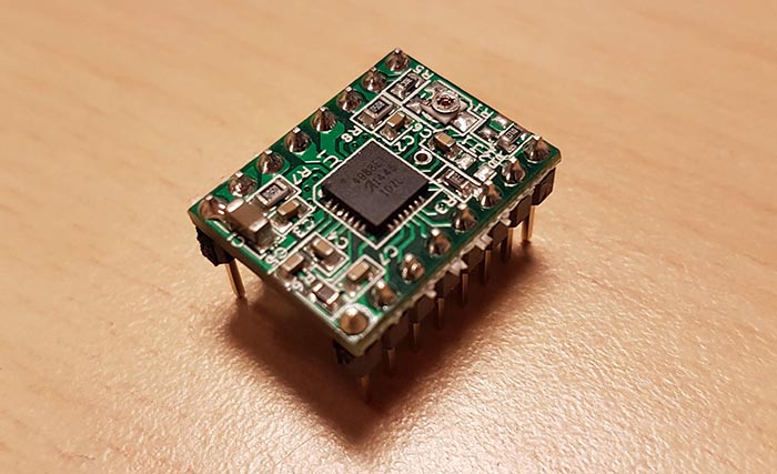
This little thing is very handy! Basically you just need to operate the DIR and STEP pins to make the motor turn. Then there are other pins for microstepping and a pin to disable the motor altogether. I didn't think disabling the motor would be important but just in case I connected it to the ATTiny (spoiler alert - it was a VERY good idea).
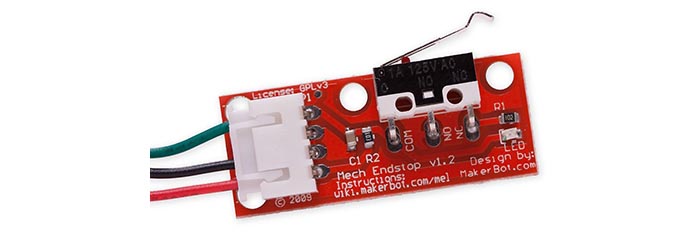
I also discovered the endstop, to check if what you drive has reached the end of the line. It's just a button that is HIGH when not in contact and LOW when triggered.
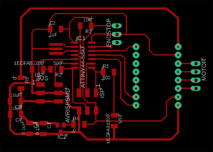
The board is not that complicated, there are just a lot of headers. I also added 2 LEDs for debugging and a resonator to get a precise clock (we figured our communication would be better). Here is the schematic:
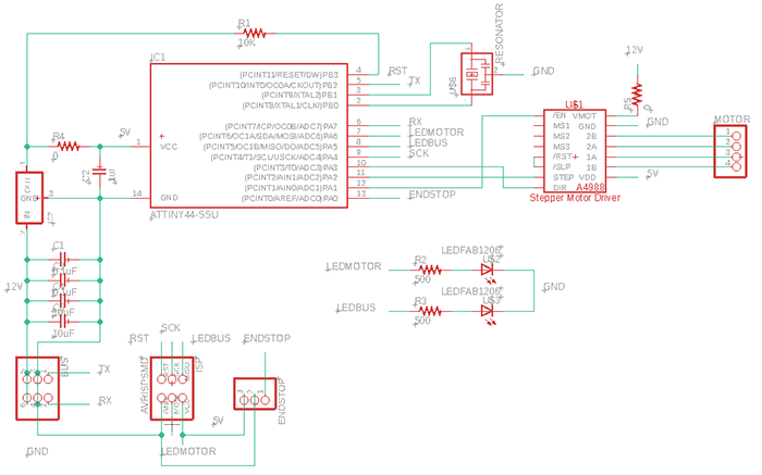
The routing was more complicated than I thought! It's the first board I had to route without any basic model actually. Designing and routing took me nearly a whole day.
Making the board
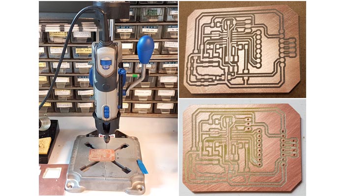
Making the board was a lot trickier this time too. The A4988 is mounted on pins and has to be soldered through holes. I didn't want to solder it on the back of my one layer copper board, because I wanted to be able to stick the board on the frame of the machine with double-sided tape. So I decided to drill the holes with the Dremel.
This proved more complicated than I thought... I tried with a 0.4mm drill and it broke. I found another drill, a little thicker (0.9mm) and drilled very slowly and carefully. It worked, but the second one was not aligned properly because of vibrations and I thought this wasn't going to work... So I thought I would start over and drill the holes with the Roland, but it seems mods doesn't do holes. I contemplated the idea of producing GCode with Eagle directly but I felt like I didn't have the time.
So I tried my hands at drilling with the Dremel again. The "trick" is to keep the Dremel on and lift the drill ever so slightly above the board while sliding the board. In the end, once I got confident with my technique, it worked pretty well!
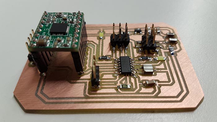
Soldering was the next challenge. Adel and Vincent warned me that soldering the pins with the headers above would be difficult. Although it seemed easy at first, I realized later that I had a lot of bad connections. Adding solder once everything was in place was a lot harder... but I managed eventually.
Programming the board
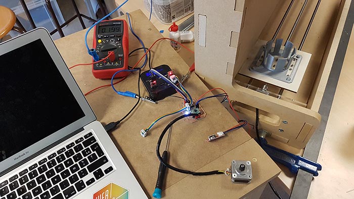
Programming the board and testing it was quite a thing too. Since I had no power jack on the board and no easy way (at first) to power my board with 12V, I decided to power it with 5V first - just to test uploading some code. It didn't work and worse, the capacitors started heating up... I didn't understand why so I just removed the capacitors that were overheating. It didn't help.
I checked my connections again and decided to test with a 12V power. And that worked! Turns out Julie had a similar issue later. So it's a good thing to remember.
Once that was out of the way I was able to upload some blinking program on my board. Next up, making the motor turn!
I used the code from the tutorial, just to check if everything was working correctly. And of course it didn't work... that's when I discovered I had bad connections at my headers. Once that was settled, it worked.
For this project we all used the Arduino IDE and the Arduino language. So the first thing I did in my code was define all the pins as constants. It's very useful because you don't want to keep checking the schematics and the pinout diagram every 5 minutes.
The pin numbers aren't the same in the Arduino language. Check the ATTiny84 pinout diagram to be sure.
#define LED_MOTOR 5
#define LED_BUS 6
#define ENABLE 1
#define STEP 2
#define DIR 3
#define TX 8
#define RX 7
#define ENDSTOP 0
As I said earlier, making the motor turn is just a matter of setting the STEP, DIR and EN HIGH or LOW in the right sequence. So I started by writing the routine to move the chariot to the origin (the endstop). I also make sure to blink the right LED to signal the user that the motor is running. LEDs are soooooo useful for debugging...
// function moving the chariot to the origin
void moveToOrigin() {
// enable motor
  digitalWrite(ENABLE, LOW);

// define direction to reverse
  digitalWrite(DIR, LOW);

// turn the motor until endstop has been reached
  while(digitalRead(ENDSTOP)) {
    digitalWrite(STEP, HIGH);
    digitalWrite(LED_MOTOR, HIGH);
    delayMicroseconds(SPEED);
    digitalWrite(STEP, LOW);
    digitalWrite(LED_MOTOR, LOW);
    delayMicroseconds(SPEED);
  }

// disable motor
  digitalWrite(ENABLE, HIGH);

// if we get here that means endstop has been reached and position is 0
  chariotPosition = 0;
  delay(500);
  blinkLedMotor();
}
What I noticed during my tests is that the motor was heating up, even tough it wasn't running. I had to adjust the potentiometer on the driver so that the current drawn by the motor was stable (200mA) and the motor's sound while turning was as low as possible.
That adjustment wasn't enough though, because even when the motor is not running it's still drawing current (up to 1A) to keep the rotor in place and that's what making the motor heat up. And that's where the ENABLE pin comes in handy! When the motor is not running I just needed to disable the FET outputs. That solved the problem.
Then I wrote a routine to make the chariot move to a certain position given as an argument:
// function moving the chariot to a certain position
void moveChariot(int dest) {
  long movement = 0;
  long absolutePosition = 0;

// enable motor
  digitalWrite(ENABLE, LOW);

// convert position into a number of steps
  switch (dest) {
    case 0:
      absolutePosition = P0;
      break;

    case 1:
      absolutePosition = P1;
      break;

    case 2:
      absolutePosition = P2;
      break;

    case 3:
      absolutePosition = P3;
      break;

    case 4:
      absolutePosition = P4;
      break;

    default:
      return;
  }

  if (chariotPosition < absolutePosition) {
// set motor direction if destination is further away than the origin
    digitalWrite(DIR, HIGH);

// calculate the amount of steps required and define new chariot position
    movement = absolutePosition - chariotPosition;
    chariotPosition += absolutePosition;
  }
  else {
// set motor direction if destination is closer to the origin
    digitalWrite(DIR, LOW);

// calculate the amount of steps required and define new chariot position
    movement = chariotPosition - absolutePosition;
    chariotPosition -= absolutePosition;
  }

// turn motor until in position but check if endstop has been reached (just in case)
  for (int i = 0; i < movement && digitalRead(ENDSTOP); i++) {
    digitalWrite(STEP, HIGH);
    digitalWrite(LED_MOTOR, HIGH);
    delayMicroseconds(SPEED);
    digitalWrite(STEP, LOW);
    digitalWrite(LED_MOTOR, LOW);
    delayMicroseconds(SPEED);
  }

// disable motor
  digitalWrite(ENABLE, HIGH);

  sendPacket(NODEID, DONE);
  delay(500);
  blinkLedMotor();
}
The routine needs to convert the position number into a number of steps (counting from the origin). Then determine in which direction to turn and the actual amount of steps the motor needs to take from the current position.
Making the network work
During our brainstorm session we decided to send 4 byte packets in a certain format with the SerialSoftware library. So I wrote the following routine to send a packet:
// function sending a packet
void sendPacket(byte dest, byte param) {
  mySerial.write(STARTBYTE);
  mySerial.write(dest);
  mySerial.write(param);
  mySerial.write(ENDBYTE);

  blinkLedBus();
}
After the initial setup routine and moving to the origin, the board is mostly listening for instructions from the master board. So the listening will occur in the loop() part of the program:
void loop() {
  digitalWrite(LED_BUS, LOW);

// byte array to store one 4 byte packet
  byte dataBuffer[4];

// read first byte
  if (mySerial.available()) {
    dataBuffer[0] = mySerial.read();

// if the byte read is the start byte then store the rest of the packet
    if(dataBuffer[0] == STARTBYTE){
      while (mySerial.available() == 0) { delayMicroseconds(1); }
      if (mySerial.available()) { dataBuffer[1] = mySerial.read(); }

      while (mySerial.available() == 0) { delayMicroseconds(1); }
      if (mySerial.available()) { dataBuffer[2] = mySerial.read(); }

      while (mySerial.available() == 0) { delayMicroseconds(1); }
      if (mySerial.available()) { dataBuffer[3] = mySerial.read(); }

// check if the packet is valid and if the packet is for this node
      if(dataBuffer[3] == ENDBYTE && dataBuffer[1] == NODEID){
        sendPacket(NODEID, ACK);
        moveChariot(dataBuffer[2]);
      }
    }
  }
}
What we're doing here is checking if the first byte received is the STARTBYTE and then get the other 3. Then if the last byte is the ENDBYTE and the the node ID is mine, the board sends an acknowledgment of receipt and does what it's supposed to. At the end of the moveChariot() routine it also sends a packet telling the master board that the job is finished.
Putting it all together
We managed to make the network work during our test phase, but, for some unknown reason at the moment, it doesn't work anymore... The master board was able to receive my packets and it was able to send me commands, which my board executed correctly. Unfortunately we weren't filming when it happened and weren't able to reproduce it on camera.
Making everything work together is probably the hardest part... especially since we all had a lot of troubles with our individual boards before connecting them together.
Here is a video of my motor running while connected to my board.
After some debugging, I found that it was my board that had a problem. It was hard to find because it was working perfectly and all of a sudden the communication part wasn't working anymore although I had changed nothing. The part of my board operating the motor was fine... but for some reason the serial communication was down.
We checked the signal with a logical analyzer and found some signal coming out of my Tx pin, but obviousely not the right one. So I tried inverting the Tx and Rx pins (in the code and physically), but still nothing. Then I used another pin for Tx (the one used for the endstop) and there it worked!
So as it turns out, you can fry one or two pins on your MCU without actually frying the whole unit! We must have made a wrong connection at some point and sent 12V directly into those pins... I'll have to change the ATTiny.
Conclusion
Although for now the whole system is not working properly, I feel like I have learned a great deal in a very short period of time! I have been debugging and learning non-stop the whole week.
I'm proud of my part of the system but also of our work as a team. We've shown a lot of solidarity and have helped each other every step of the way. We worked well as a team and our method was good I think. We just haven't had enough time to finish...