Week 16: Interface and Application Programming
05/14/2019 - Stéphane Muller
Individual assignment: write an application that interfaces with an input &/or output device that you made. Group assignment: compare as many tool options as possible
For this week I decided to start with something not too complicated and then start working on the interface for my final project. So for this week's project I used Processing and then I will try my hand with Python.
Planning and list of tasks
- Phototransistor level display
- LED control
Step by step
Phototransistor level display
First thing I noticed about Processing is that the interface is very similar to Arduino IDE. The language is almost the same as well. It felt very familiar and was quite easy to master.
For this project I used my board from input week. My goal was to be able to visualize the reading from the phototransistor on my screen, with the help of a gauge, just like in Neil's examples.
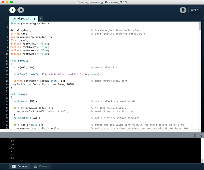
First thing I did was look at the code examples provided with the software. I adapted the code used to read a value from a serial interface and drew a dynamic gauge.
The program structure is basically the same as for Arduino: you've got your setup() block to initialize your variables and objects, and then you have the draw() loop, where you put your code.
void setup()
{
  size(440, 120);                                     // set window size

  textFont(createFont("AvenirNextCondensed-Bold", 14, true));

  String portName = Serial.list()[1];                 // open first serial port
  myPort = new Serial(this, portName, 9600);
}
In the setup I start by setting the window size, then by defining a font for the text I want to display and finally I instanciate my Serial object to open a serial connection.
void draw()
{
background(255); // set window background to white
if ( myPort.available() > 0) { // if data is available,
val = myPort.readStringUntil('\n'); // read it and store it in val
}
println(trim(val)); // get rid of the return carriage
if ( val != null ) { // sometimes the value sent is null, to avoid errors we skip it
measurement = int(trim(val)); // get rid of the return carriage and convert the string to an int
level = (float) measurement*255/1024; // map the value on 255 (knowing that the max value is 750)
bgcolor = int(level); // the math gave us a float but we need an int
fill(255);
rect(50, 50, 255, 10); // draw the gauge container
fill(100);
rect(50, 50, bgcolor, 10); // draw the gauge
fill(255-bgcolor); // set fill to the light level
rect(30, 50, 10, 10); // draw a symbolic phototransistor to display the luminosity level
fill(100);
text("Light level: " + bgcolor, 325, 60); // display the actual value sent by the board
}
delay(50); // add a delay to avoid flickering of the displayed elements
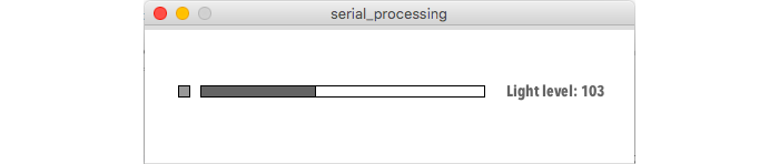
}Then in the draw block, I read the data from the serial port, I trim the value to get rid of the return carriage and then I draw the various GUI elements. The first square symbolizes the light received by the phototransistor (when it's white it detects a lot of light and when it's black it doesn't detect any). Then the gauge is just a representation of the value sensed by the ATTiny.
Below is the final result as well as a demo video.
I added a 50ms delay to avoid the interface to flicker when it's updated after each loop.
LED control
Reading a value is all good and well, but I also wanted to be able to control a board from my computer. So my second goal was to control the 4 LEDs that were on the board. To do that I had to write a new program for the board and write a program for the computer.
The code for the board was pretty straightforward. I just used the get_char() from Neil and wrote a function to handle each possible command I could receive.
get_char(&serial_pins, serial_pin_in, &chr);
switch(chr)
{
case '1' :
turnOn(1);
break;
case '2' :
turnOn(2);
break;
case '3' :
turnOn(3);
break;
case '4' :
turnOn(4);
break;
default :
bouncy();
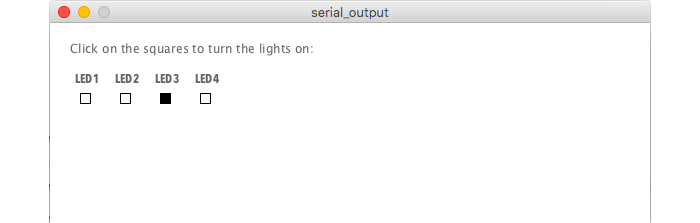
}For the Processing part I made 4 buttons and sent a number via serial depending on which one you clicked.
I used the following code for the buttons. It changes color when you hover over it and it becomes black when the LED is on and goes back to white when you click it again and the LED is off.
  if (mouseOverRect1() == true) {                     // if mouse is over square,
    rectOver1 = true;                                 // store it in a variable and
    fill(204);                                        // change color of the square
  } else {
    rectOver1 = false;                                // else, store it in a variable
    fillcolor = (led1 == true) ? 0 : 255;             // display if the LED is on or off
    fill(fillcolor);
  }

  rect(30, 70, 10, 10);                               // and draw the square

  fill(100);
  text("LED1", 25, 60);
To make the code lighter I used a shorthand for the if-then-else statement. Variable = (test expression) ? (value if true) : (value if else);
boolean mouseOverRect1() {                             // test if mouse is over square
  return ((mouseX >= 30) && (mouseX <= 40) && (mouseY >= 70) && (mouseY <= 80));
}
This code checks the position of the mouse and returns true if it is in a certain area.
void mousePressed() {
  if (rectOver1) {
    myPort.write('1');
    led1 = !led1;
  }

  if (rectOver2) {
    myPort.write('2');
    led2 = !led2;
  }

  if (rectOver3) {
    myPort.write('3');
    led3 = !led3;
  }

  if (rectOver4) {
    myPort.write('4');
    led4 = !led4;
  }
}
This function tells the program what to do when there is a click depending on the area the cursor is over.
And here is the final result, followed by a demo:
All in one
I wanted to put everything into one program but the board can't listen to serial AND output values at the same time unfortunately.
Conclusion
It was interesting to be finally able to do what Neil showed us in his examples. I'm a big fan of data visualization and I can't wait to play around with other frameworks. I've used d3js in the past and I just discovered visjs.
For my final project I intend to use the Python framework Flask.