Week nine: Embedded programming
Individual assignment
For this task, we have to identify relevant information in a microcontroller data sheet and program the board we made in the week six Electronic Design.
Datasheets
Before starting to program, we must recognize the most relevant datasheet of the microcontroller we want to use, to know how many ports it has, which are analog and which are digital, for which pins the communication we want is established, etc.
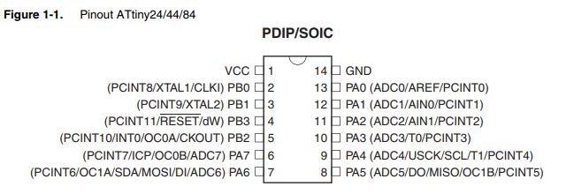
Attiny 44
You can read the attiny 44 datasheet
following this link
And I learned that this microcontroller has an internal oscillator of 8Mhz, but it can be placed on the external electronic board, it has 14 pins in total, of which number 1 is VCC and number 14 GND, 5 digital inputs and 2 analog inputs , pins 4, 7, 8 and 9 (Reset, MOSI, MISO and SCK respectively) will be used for ISP communication, to boot bootloader, the microcontroller can also be programmed by these pins if the ISP energizes the board, as is my case, since my ISP is based on Ali's model. You can use pins PB0 and PB1 for PWM.
That information was important, for example in week 12 output devices needed a PWM pin to connect it to the motor i used.
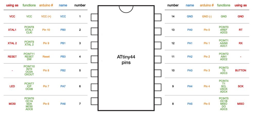
The following image shows the compatibility of pins in arduino
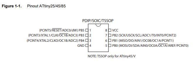
Attiny 45
You can read the attiny 45 datasheet
following this link
This microcontroller also has an internal clock, has 8 pins of which pin number 4 is used as GND and pin number 8 as VCC, 1, 5, 6 and 7 (Reset, MOSI, MISO and SCK respectively) will be used for ISP communication, burn bootloader or load the program if you have an ISP that energizes the electronic board.
That information was important, for example in week 14 Networking and communications i needed communication pins to serial bus
ISP Connection
To be able to program the attiny microcontrollers from windows and using the arduino IDE, I followed this tutorial that indicates to download and install Atmel GNU toolchain, GNU make, AVR dude and the drivers to be able to recognize my ISP programmer in my laptop

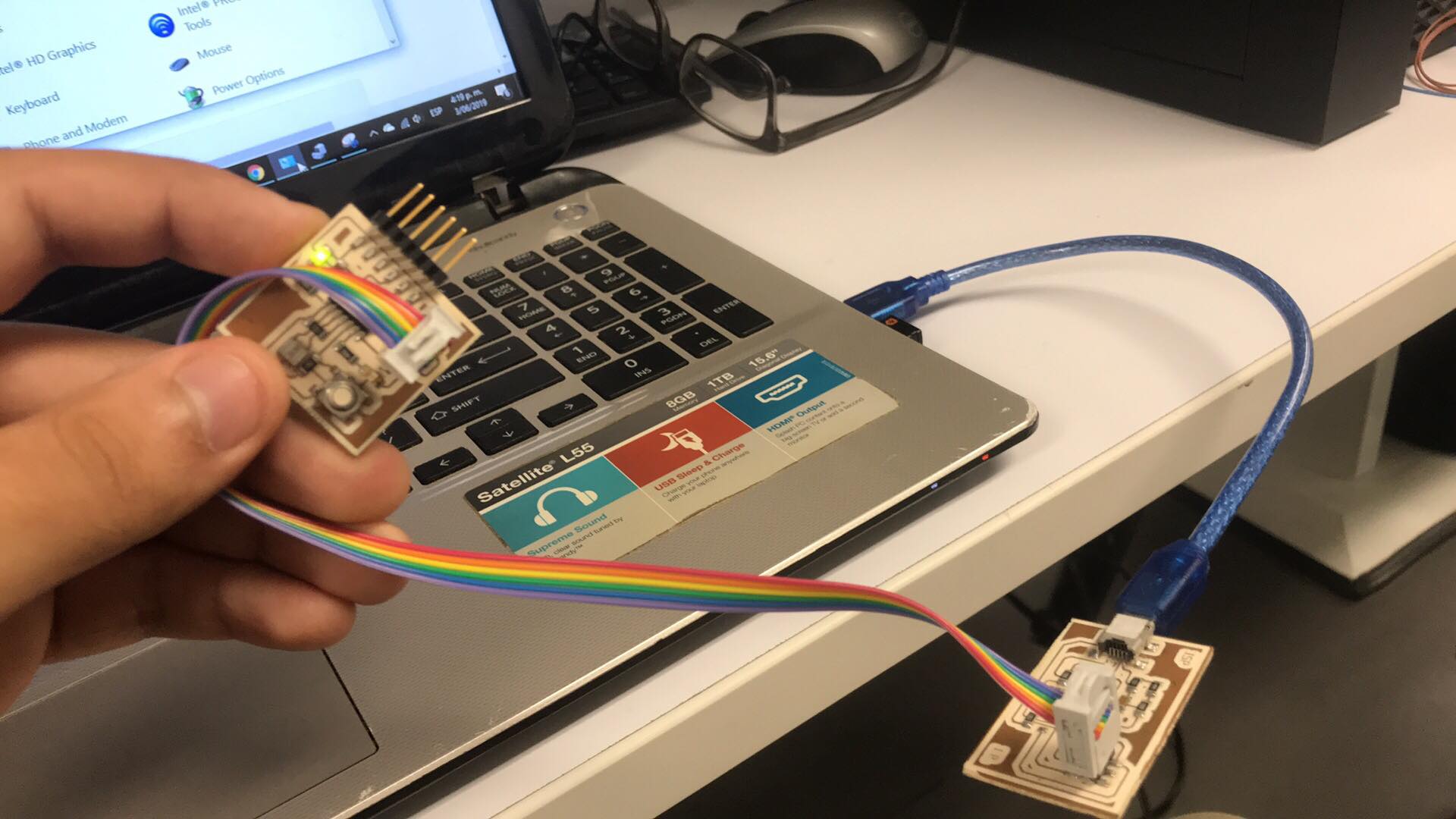
You can see how my electronic board is powered by my laptop through the ISP,
because my model is based on the isp of Ali and this has a bridge that allows to energize boards in addition, the cable that I have allows the connection with the pins MISO, MOSI, SCK, RST, 5V and GND, which manages to record the program in the microcontroller for this reason I can program it without needing an FTDI
I could also load the program using the FTDI, which has 4 pins that are connected to the microcontroller, VCC, GND, Rx and Tx, thanks to this it allows serial communication with the computer (master) which could not only be done by the ISP and this is crucial when you want to read data from analog inputs such as temperature, pressure, light sensors, etc.
In conclusion, to burn bootloader is necessary the ISP, to load the program you can use the FTDI or the ISP as you prefer and to achieve communicate by serial port the values of analog variables is essential the FTDI
Arduino language
I downloaded GNU toolchain, for this I will use arduino IDE.
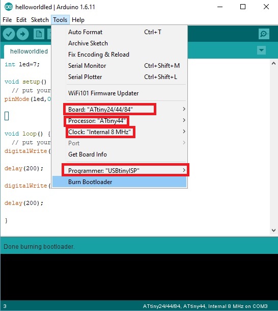
To be able to program the electronic board, it is necessary to burn bootloader, for this we configure in the following way:
Board: ATtiny 24/44/84
Processor: ATtiny44
Clock: Internal 8MHz or External 20MHz
Programmer: USBtinyISP
And click on BURN BOOTLOADER
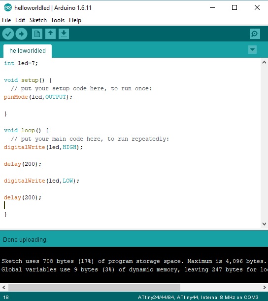
Then, i wrote a code to blink the led of the board:
int led=7;
void setup() {
// put your setup code here, to run once:
pinMode(led,OUTPUT);
}
void loop() {
// put your main code here, to run repeatedly:
digitalWrite(led,HIGH);
delay(200);
digitalWrite(led,LOW);
delay(200);
}
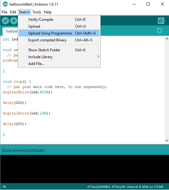
And click on Upload using programmer, because my ISP is energizing the board
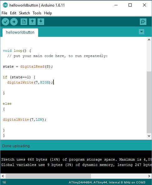
Button+LED
int state=0;
void setup() {
// put your setup code here, to run once:
pinMode(7,OUTPUT);
pinMode(8,INPUT);
}
void loop() {
// put your main code here, to run repeatedly:
state = digitalRead(8);
if (state==1) {
digitalWrite(7,HIGH);
}
else
{
digitalWrite(7,LOW);
}
}
I also programmed my atmega 328p, i design and fabricated this board in week 16 but im updating this week with an example of how to use a library in arduino IDE
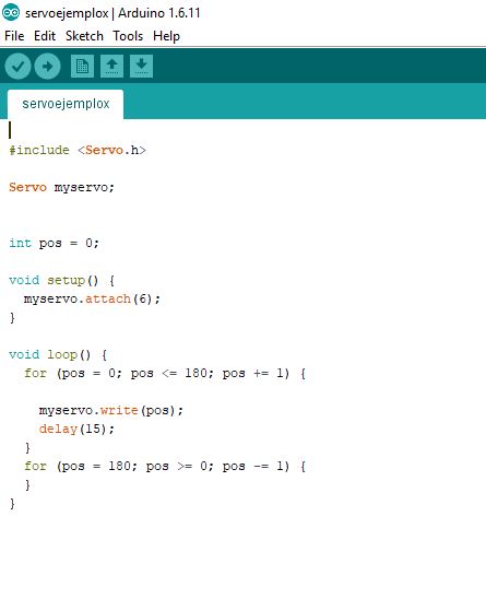
#include
int pos = 0;
void setup() {
myservo.attach(6);
}
void loop() {
for (pos = 0; pos <= 180; pos += 1) {
myservo.write(pos);
delay(15);
}
for (pos = 180; pos >= 0; pos -= 1) {
}
}
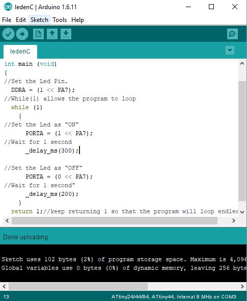
C language
I found this code in a repository and modified the time the LED stays on and off
int main (void)
{
//Set the Led Pin.
DDRA = (1 << PA7);
//While(1) allows the program to loop
while (1)
{
//Set the Led as "ON"
PORTA = (1 << PA7);
//Wait for 1 second
_delay_ms(300);
//Set the Led as "OFF"
PORTA = (0 << PA7);
//Wait for 1 second"
_delay_ms(200);
}
return 1;//keep returning 1 so that the program will loop endlessly
}
What questions do you have? What would you like to learn more about?
The main question I had for this week was how could I program the microcontrollers using arduino libraries, the answer was to use the atmega 328, which has more digital and analog pins, besides compatibility with all the arduino libraries, besides having more memory , that is why I manufactured it in week 16, I would like to learn more about C language, since it is the basis of other languages
Downloads
Arduino Blink code
Arduino Button + LED
C Blink code in arduino IDE
Servomotor code
To see the complete development of the group assignment visit the following link that corresponds to the CIT page