Final project
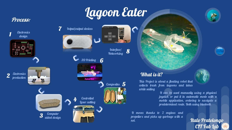
Pollution in my country seems to be normalized, people usually throw waste on beaches, lakes and lagoons, so I want to create a floating robot capable of cleaning debris while browsing, I would like to have a manual mode, to control the robot with a joystick and one automatic, to let it travel with a predetermined route and clean garbage in a given time
In summary this is the result of my final project
First sketches
At the beginning I thought about making a robot with only one head with 2 nets on the sides, however I realized that I would have stability problems, besides I could not collect so much garbage, so I decided to do it with 2 heads and a network in the middle, the idea is that by just navigating clean gaps!
Here you can see the bill of materials of my final project

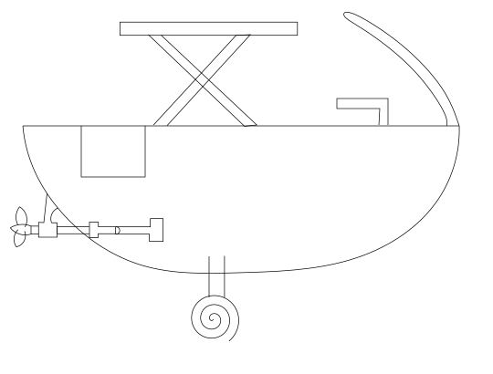
This was in the beginning the model that I was going to use as a robot, over time I changed it
3D Design
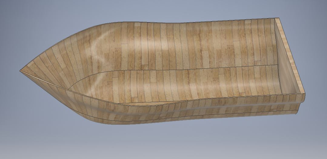
With 2 of these heads I will have more stability

I did a small test printed in 3D to see the buoyancy and stability
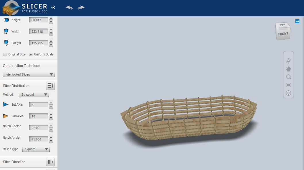
Controlled laser cutting
The next step was to make the skeleton of the ship, this will be useful to distribute the weight in the waterproof layer that I will do, in addition all the structure and supports of the ship will be embedded in the skeleton pieces.
Then, export the files that the software worked on in dxf, for later laser cutting. Thanks to the software I separated with color the orientation marks to assemble the structure of the cutting lines, in the laser cutter I first made the marks and then the cuts
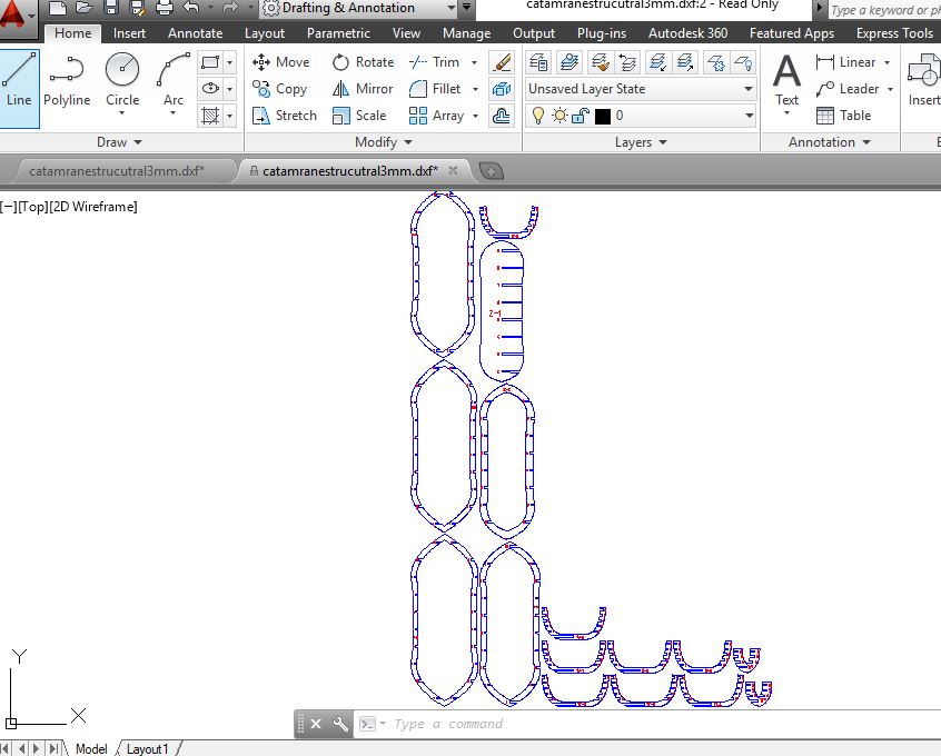
The material I used was MDF with a thickness of 3 millimeters: Therefore I used the following parameters:
Vector
Orientation marks:
Speed: 80%
Power: 100%
Frequency: 100%
Cutting of pieces:
Vector
Speed: 5%
Power: 100%
Frequency: 100%
I could make the marks with raster, but it would have taken much longer, so I decided to use vector with high speed, I reduced the line width to 0.00015 to achieve this
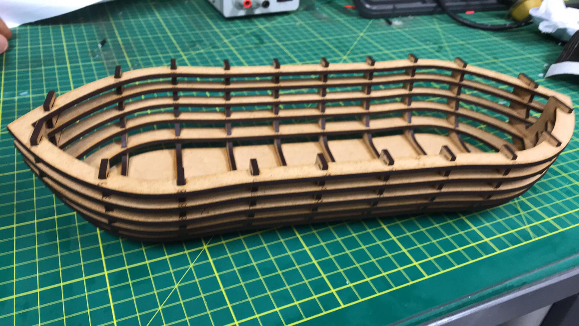
Then I assembled all the pieces with the help of the orientation marks obtaining the following result
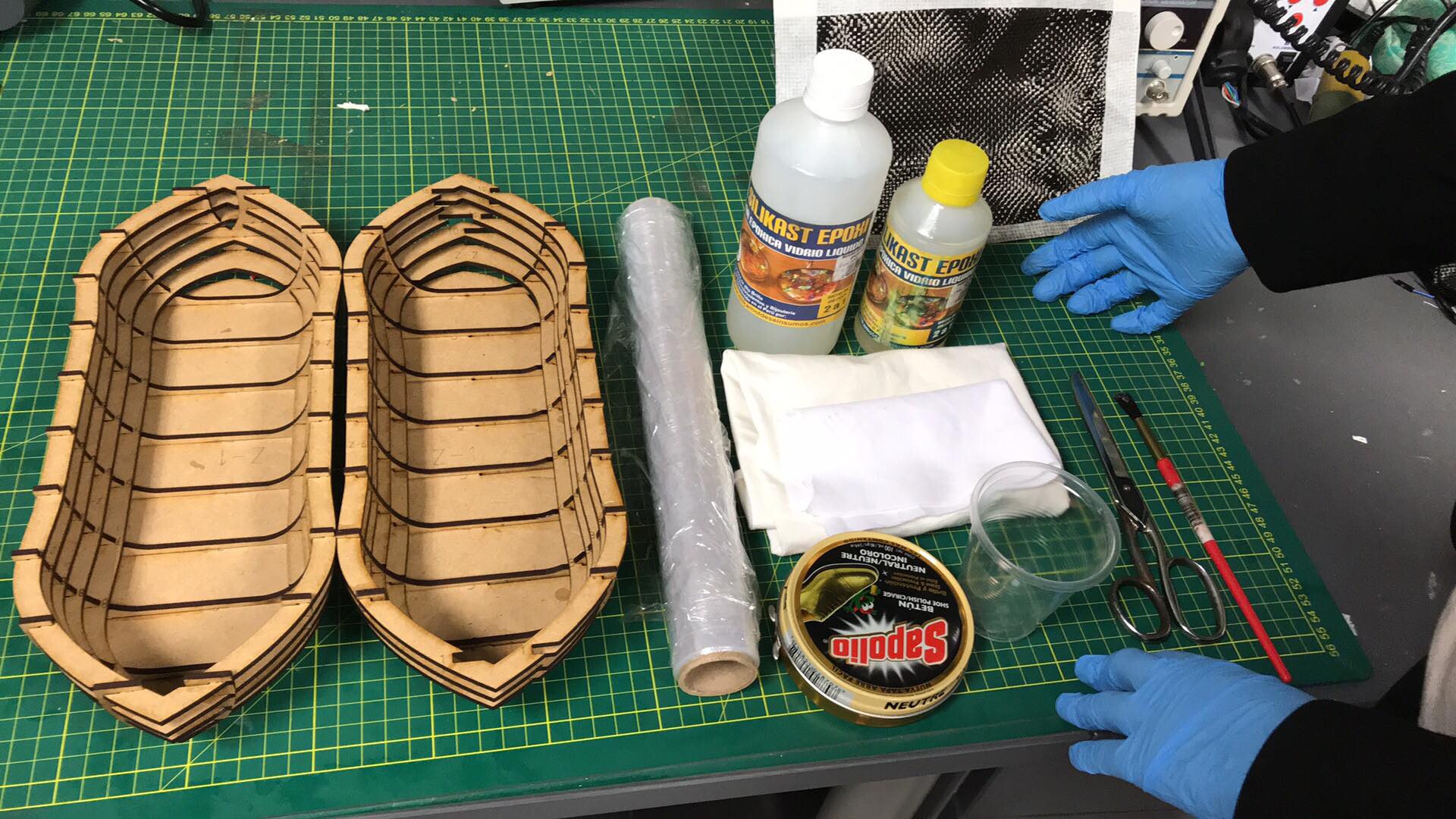
Composites
I already have 2 skeletons for each head of the robot, what follows is to create a lightweight, resistant and especially waterproof material, since it will be in contact with water
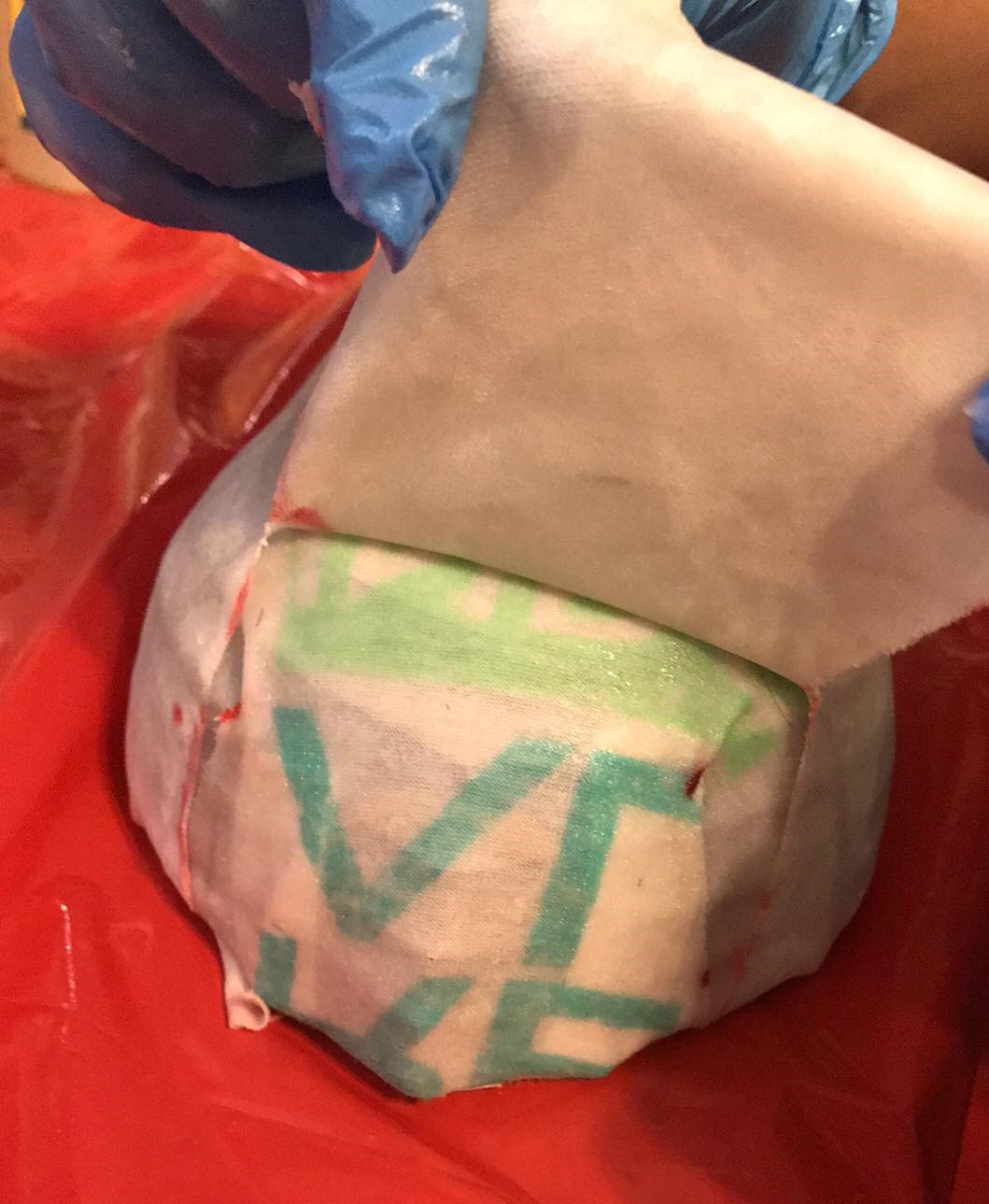
This I achieved thanks to what I learned in the week 18 wildcard week, basically I combined 2 different fabrics with epoxy resin and got what I wanted, for more information check the link of week 18: Composites
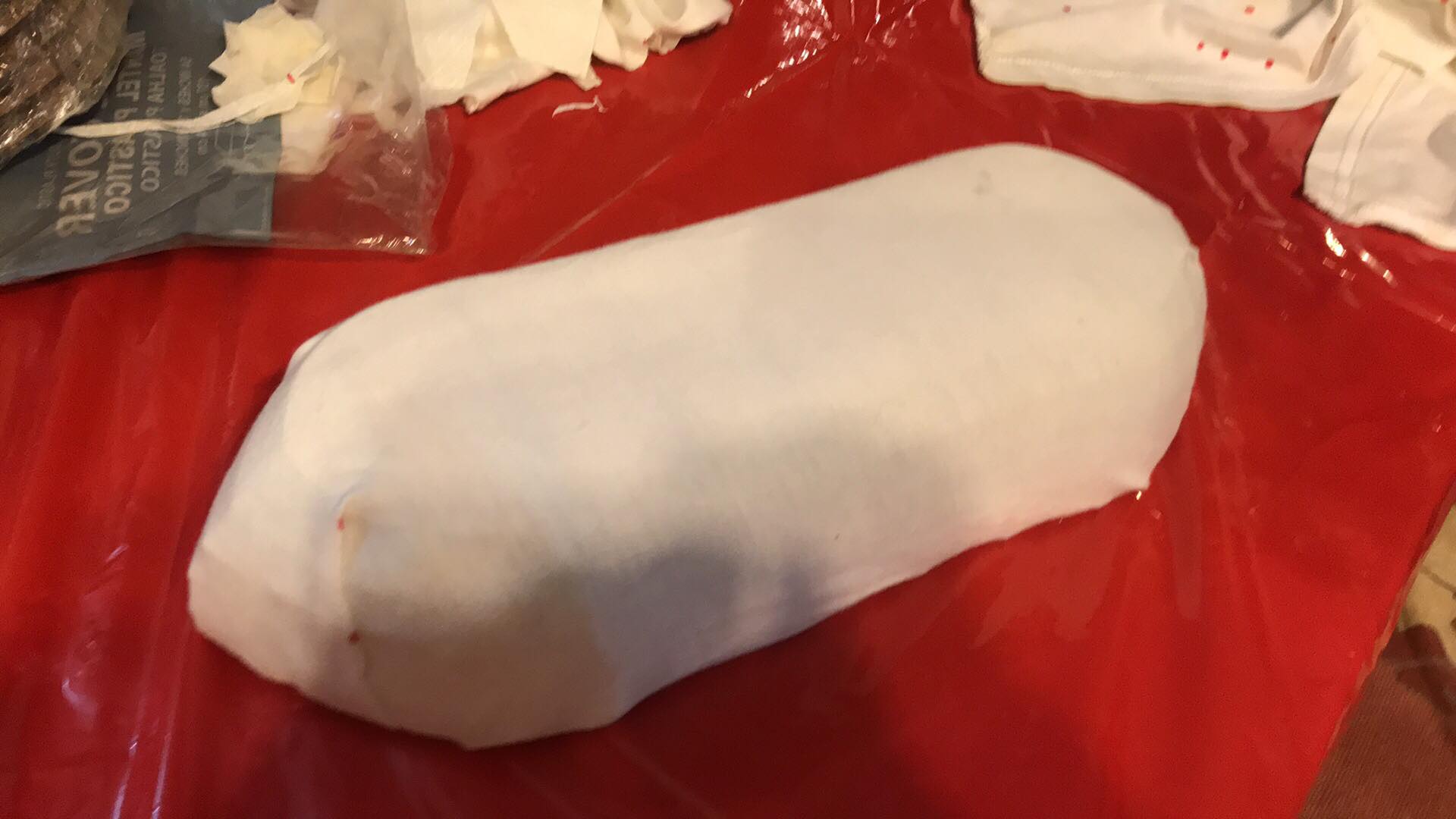
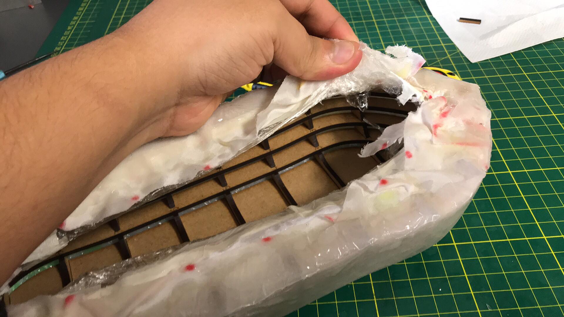
The first thing I did was to wrap the structure with film, in this way I avoid that the resin is in contact with the MDF, since it would be absorbed and swollen, besides this way it will be easier to remove the excess fabric
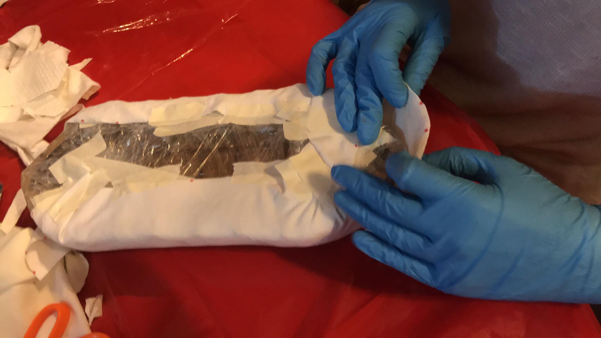
Result of the first layer of polyester
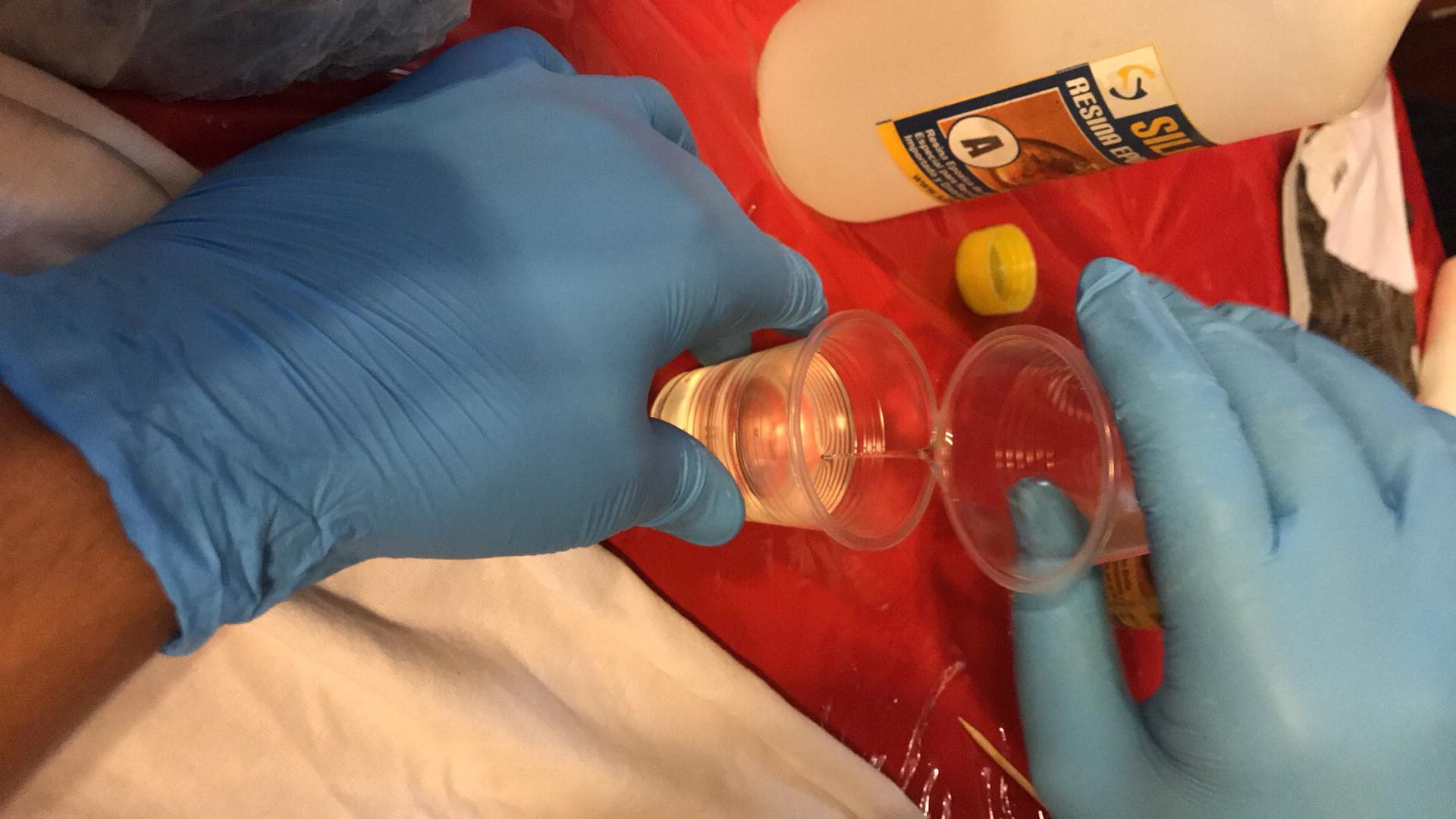
I proceeded to pour the epoxy resin into a disposable cup to start mixing
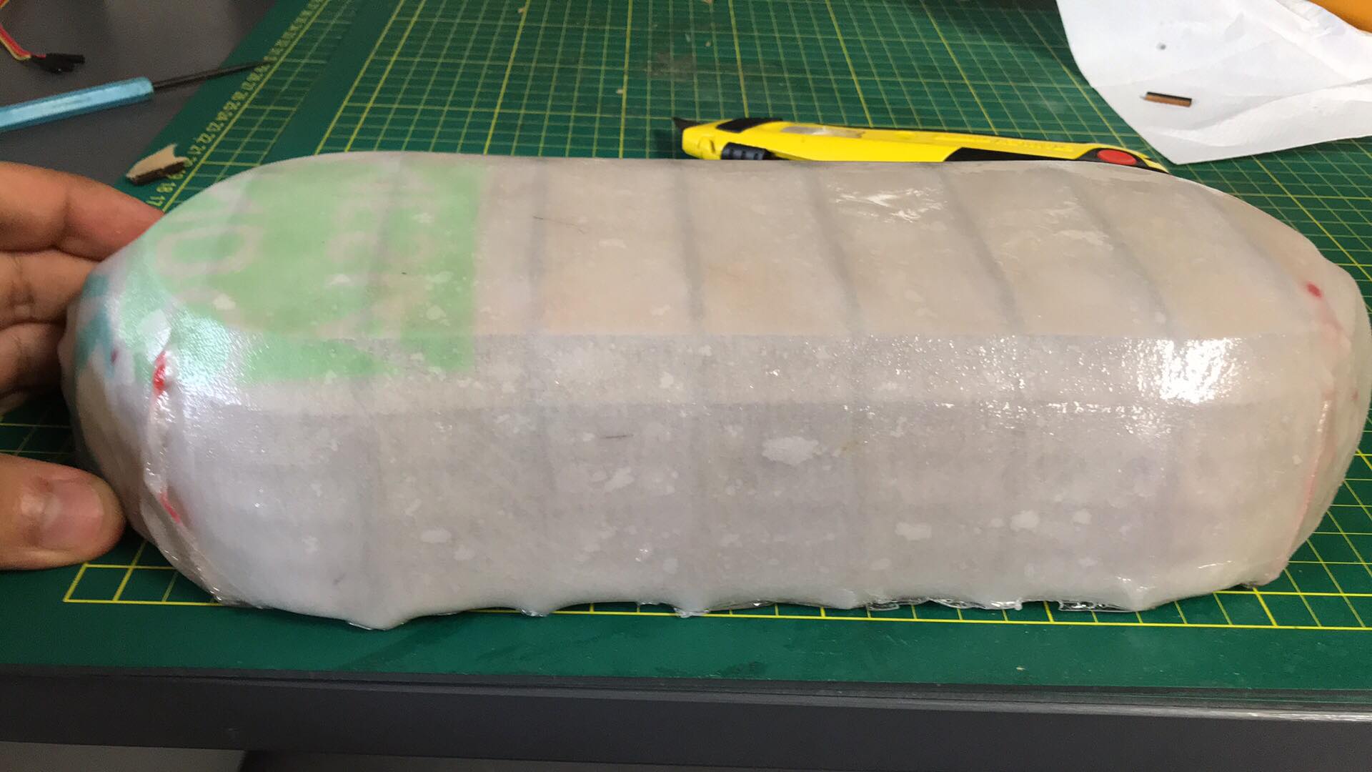
When the resin hardened completely I proceeded to remove everything that is not part of the composite with the help of a pair of scissors and a cutter
Here I perform a composite test on water, nice results!
3D Printing
As I mentioned before, I was going to design and print all the elements of the structure, supports for motor, net, etc, then I explain the functionality.
The next element will be embedded in the skeleton of the boat and will be responsible for holding the net that will load garbage, I printed 2 because the network will be supported by 2 pillars, one in each head.
.JPG)
The next element is a support for the engine, which will be embedded in the skeleton of the ship, these measurements were obtained from measuring with digital vernier, in addition to knowing the tolerances of 3D printing thanks to week 6
.JPG)
The next piece is very important, since it will be the axis that connects both heads, it must have a fairly fixed position, also within this axis will pass the cables of one motor to reach the other side's plate, for this reason I decided to cover 3D printing with resin to make it waterproof
.JPG)
This is the other half of the piece
.JPG)
I will use this box to place my plates, and seal it with acrylic to make it waterproof
.JPG)
And the most important piece is the following, the propeller that will allow the robot to move in the water, the design is similar to the Leonardo da Vinci shovel boat, the advantage is that I have 2 motors

Here is a video of the printing of the propeller
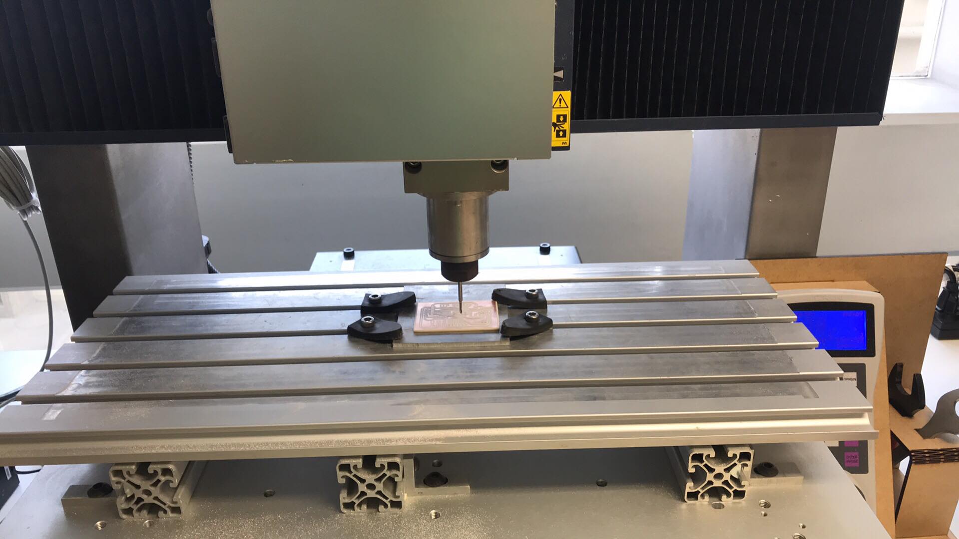
Electronics Design and Production
I designed and manufactured a board with the atmega 328 microcontroller, I decided to use it due to its capacity and it is compatible with the arduino libraries, I also need several output pins, since they are 2 motors that I want to control and must have communication pins for use bluetooth
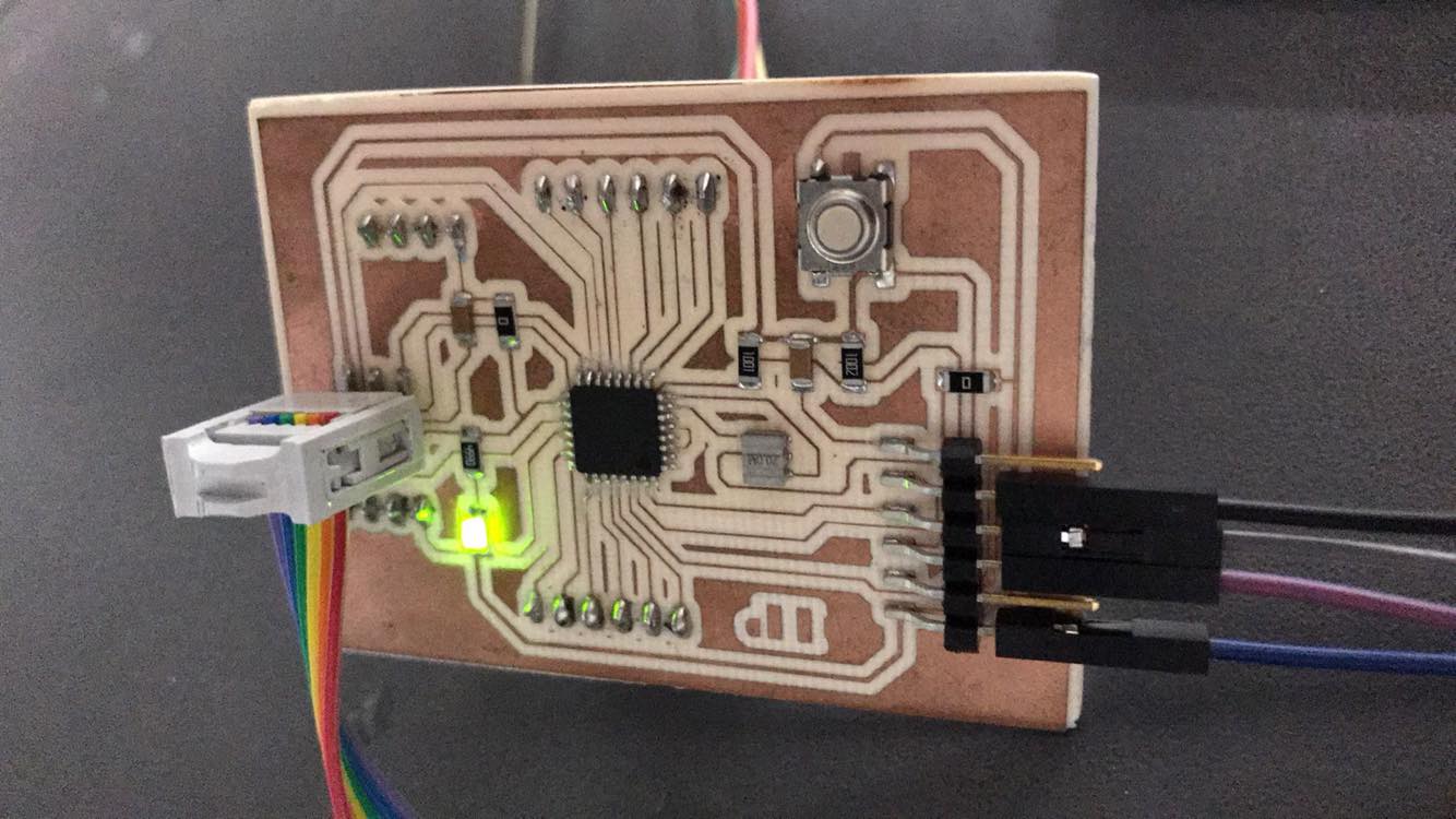
I added a 5V regulator for the batteries to feed this voltage to the atmega328.

Here is the design in my board

And this is the final result of my plate, if you want to know more about the manufacturing process visit Week 5 Electronics production
Programming
First, i burnt bootloader,
then I could start with programming in arduino language
My project has 2 modes, manual and automatic, in manual mode it is controlled by a joystick via bluetooth and the automatic starts with an order sent by an app, which sends a variable type text which is the mark to start the loop

#include
SoftwareSerial miBT (10,11);
char DATO=0;
int velocidad=0;
int enA = 9;
int in1 = 8;
int in2 = 7;
int auxiliar=0;
int auxiliar1=0;
int auxiliar2=0;
int auxiliar3=0;
int auxiliar4=0;
int contador=0;
// Motor B
int enB = 3;
int in3 = 5;
int in4 = 4;
// Joystick Input
int joyVert = A0; // Vertical
int joyHorz = A1; // Horizontal
// Motor Speed Values - Start at zero
int MotorSpeed1 = 0;
int MotorSpeed2 = 0;
// Joystick Values - Start at 512 (middle position)
int joyposVert = 512;
int joyposHorz = 512;
void setup()
{
// Set all the motor control pins to outputs
miBT.begin(38400);
Serial.begin(9600);
pinMode(enA, OUTPUT);
pinMode(enB, OUTPUT);
pinMode(in1, OUTPUT);
pinMode(in2, OUTPUT);
pinMode(in3, OUTPUT);
pinMode(in4, OUTPUT);
pinMode(13,OUTPUT);
// Start with motors disabled and direction forward
// Motor A
// digitalWrite(enA, LOW);
// digitalWrite(in1, HIGH);
// digitalWrite(in2, LOW);
//
// // Motor B
//
// digitalWrite(enB, LOW);
// digitalWrite(in3, HIGH);
// digitalWrite(in4, LOW);
//
}
void loop() {
if(miBT.available()){
DATO=miBT.read();
// Read the Joystick X and Y positions
if (DATO=='1'){
auxiliar=1-auxiliar;
if(auxiliar==1){
//set motor a backward motor adelante
digitalWrite(in1, HIGH);
digitalWrite(in2, LOW);
// Set Motor B backward
digitalWrite(enA,HIGH);
digitalWrite(enB,HIGH);
digitalWrite(in3, HIGH);
digitalWrite(in4, LOW);
}else {digitalWrite(enA, LOW);
// Motor B
digitalWrite(enB, LOW);
}
}
if(DATO=='2'){
auxiliar1=1-auxiliar1;
if(auxiliar1==1){
//set motor a atras
digitalWrite(in1, LOW);
digitalWrite(in2, HIGH);
digitalWrite(enA,HIGH);
digitalWrite(enB,HIGH);
// Set Motor B atras
digitalWrite(in3, LOW);
digitalWrite(in4, HIGH);}
else {digitalWrite(enA, LOW);
// Motor B
digitalWrite(enB, LOW);
}
}
if(DATO=='3'){
auxiliar2=1-auxiliar2;
if(auxiliar2==1){
//giroa la derecha
//set motor b adelante
digitalWrite(in3, HIGH);
digitalWrite(in4, LOW);
digitalWrite(enB,HIGH);
// Set Motor a detenido
}else{ digitalWrite(enB,LOW);}
}
if (DATO=='4'){
auxiliar3=1-auxiliar3;
if(auxiliar3==1){
// giro a la izquierda
//motor b detenido
//motor a delelante
digitalWrite(in1,HIGH);
digitalWrite(in2, LOW);
digitalWrite(enA,HIGH); }
else{digitalWrite(enA,LOW);}
}
//modo automatico
if (DATO=='5'){
auxiliar4=1-auxiliar4;
if(auxiliar4==1){
//ir adelante primera vez
digitalWrite(in1, HIGH);
digitalWrite(in2, LOW);
// Set Motor B backward
digitalWrite(enA,HIGH);
digitalWrite(enB,HIGH);
digitalWrite(in3, HIGH);
digitalWrite(in4, LOW);
//ir derecha primera vez
delay(4000);
digitalWrite(in3, HIGH);
digitalWrite(in4, LOW);
digitalWrite(enB,HIGH);
digitalWrite(enA,LOW);
delay(1000);
//ir adelante segunda vez
digitalWrite(in1, HIGH);
digitalWrite(in2, LOW);
// Set Motor B backward
digitalWrite(enA,HIGH);
digitalWrite(enB,HIGH);
digitalWrite(in3, HIGH);
digitalWrite(in4, LOW);
delay(4000);
//ir derecha segunda vez
digitalWrite(in3, HIGH);
digitalWrite(in4, LOW);
digitalWrite(enB,HIGH);
digitalWrite(enA,LOW);
delay(1000);
//ir adelante tercera vez
digitalWrite(in1, HIGH);
digitalWrite(in2, LOW);
// Set Motor B backward
digitalWrite(enA,HIGH);
digitalWrite(enB,HIGH);
digitalWrite(in3, HIGH);
digitalWrite(in4, LOW);
delay(4000);
//ir derecha tercera vez
digitalWrite(in3, HIGH);
digitalWrite(in4, LOW);
digitalWrite(enB,HIGH);
digitalWrite(enA,LOW);
delay(1000);
//ir adelante cuarta vez
digitalWrite(in1, HIGH);
digitalWrite(in2, LOW);
// Set Motor B backward
digitalWrite(enA,HIGH);
digitalWrite(enB,HIGH);
digitalWrite(in3, HIGH);
digitalWrite(in4, LOW);
delay(4000);
//ir derecha cuarta vez
digitalWrite(in3, HIGH);
digitalWrite(in4, LOW);
digitalWrite(enB,HIGH);
digitalWrite(enA,LOW);
delay(250);
digitalWrite(enA,LOW);
digitalWrite(enB,LOW);
}
else {digitalWrite(enA,LOW);
digitalWrite(enB,LOW);
}
}
}
}
Once the programming, electronic and manufacturing parts were obtained, I proceeded to assemble everything and test it in the water, which is where it will work

As i mentioned before, i put the cables of one motor inside the axis

Once all the electronics were placed in the boxes and in the head, I proceeded to cut with laser press fit with the figure of the boat, to seal it with silicone and be waterproof

Finally, I tried it in the water, but I had a problem, because I printed the propellers with low infill to reduce the time, then one fell into the water and the robot kept turning, so I printed a better quality one
After learning of the error, I tried again this time sealing each head with acrylic and silicone. Below you can see a summary video and the robot working in its 2 modes of operation
To watch te video press right click and then show controls, you shoul play the video