12. Output devices
For the output week I have decided to design an arduino board that has Atmega328P Microcontroller and if it worked will I am going to use it for my final project.
What is Arduino?
Before I start designing my circuit I had to understand what is arduino at first so I tried to understand what is it and the following vidoes helped me to know more about arduinos:
Main Arduino Components:
- USB Port: Connects to the user computer for recieving and transmiting programing and data.
- DC Power Jack: can be attached to power supply or a batteries pack so once the Arduino is programmed, it can be detached from the computer and put on the go.
- Timer chip: the heart of the circuit board it is crystal timer chip whose rapid steady heartbeat provides the clock input that regulates the micro-processor.
- Atmega 328: the brain of the arduino.
- Headers: When building a circuit, you stick wires in the holes in the top and they connect to the micro-chip without missy soldering. These holes can provide power for your circuit from the arduino voltage.
- Analog in Headers: a collection of headers, say that you have a sensor, it could be a light sensor or temprature sensor or whatever, the point is the sensor data isnt just 0 or 1, high or low, it is a gradient of values that analog data for you and if you want arduino to read it, this is where you connect it.
- reset button: does what the name implies.
- Digital input/ouput Headers: each connection atop the header can be programmed for digital input or output. the little marks nexts to the pins 3,5,6,9,10 and 11 indicate that they can be programmed for PWM which stands for Pulse Width Modulation and desipte the similarity to PWN, has nothing to do with infliction, humilation, defeat on you adversary. as for what PWM does do. it can provide light dimming and motor speed control through digital outputs.
- built in LEDs: when a signal is recieved from the computer the Rx LED flashes. anyhow the TX is for transmit as you might guess. the last LED which connect the i/o pin is which means you can test the circuit without having to insert an external LED.
Designing and Fabricating My Own Arduino
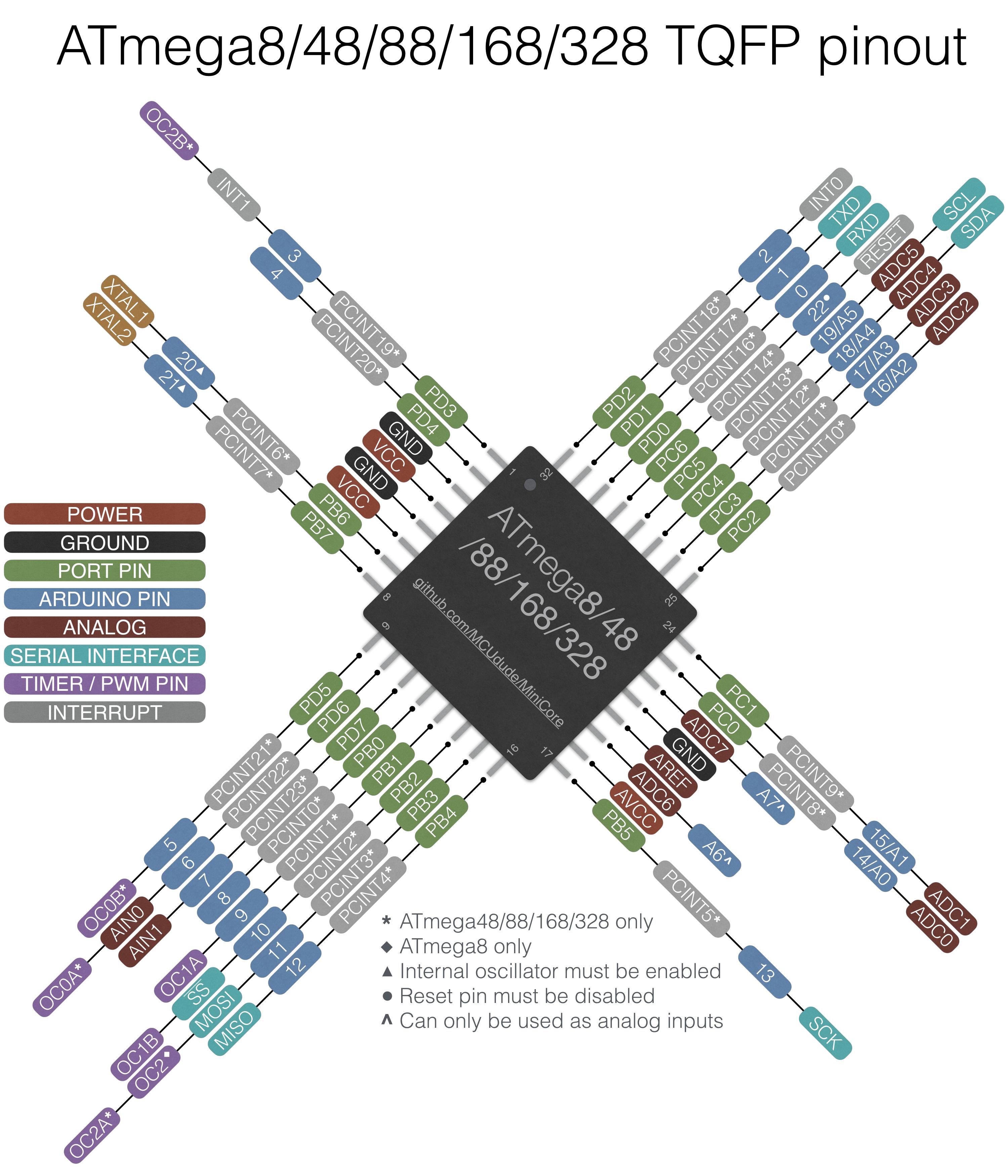
Micro-controller : Atmega328P
It is important to review the Datasheet for Atmega328P. I have reviewed it to understand the pins configuration:


The chip pinouts are:

Furthermore, Refering to YourDuinoEngStarter
~ The diagram shows how we will connect things to Arduino and what it means if something is connected or switched to HIGH=5V or LOW=0.0V :
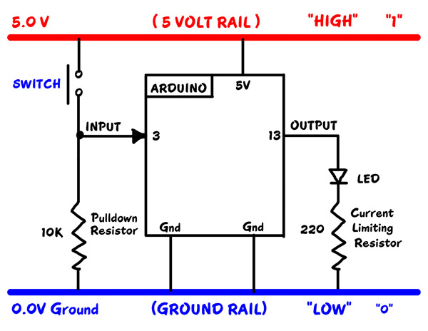
- DIGITAL “SIGNALS”:
When a PIN (or wire or connection) changes from 0 to 1, or 1 to 0, we say it is a SIGNAL. Kind of like someone raising up a flag or lowering it.
- DIGITAL OUTPUT “SIGNALS”:
An LED or Buzzer connected to an Arduino OUTPUT can “signal” you that something has happened.
- DIGITAL INPUT SIGNALS:
If you push a button that changes an INPUT, you “signal” Arduino that something should be done.
Board Design and Fabriction
Components

Schematic
After I checked the available components in the lab I inserted them in Eagle:

Then I have Connencted them based on the chip pinouts

Eagle Design Rules (DRC)
Before I start desgining the route I have changed the DRC as the following:


Final Board Design

I had to add two jumper for the routes connections

in this area I had to make wire width to 14

and around the micro-controllers as the pins were too small I had to change the wires on that area to 12

then the design was exported as for the traceses I hided all the layers except the top and reference layers:

then I exported the file as the following:

then I have hided all the layers except the dimension layer and export another image as it the edge of the board.

Milling: Fab Modules

a clear screenshot of the results

after that I downloaded the rml file and used it for milling
Soldering
As I had so many components in this circuit I decided to start with the most difficult component to be soldered as it had the most connections which is the micro controller.
I used the flux pen before soldering every component.

for the micro-controlled I taped the micro-controller as the following to make sure I solder on the right location:

More tips on soldering can be found on Week5-Electronics Production-Soldering Section
Outcome:

Problem Faced
I accidently grabbed the FTDI header and broke it

so I took a superglue and stick it
interesting fact I have figured out: the superglue is an insulated material so I was generous when I was using it. I waited it to dry and then I soldered on and by the soldering I conneted the wires.
Testing the Board


Programming
for the output I decided to program a stepper motor
28BYJ-48 – 5V Stepper Motor Datasheet


so I used my programmer that we had made in Week5-Electronics Production where I connected the ISP headers together then I used an Auruino as a power supply to my board so I looked for vcc pins and ground pins on my fabduino circuit and then connceted it to the arduino. after that, for the stepper motor it was connected to power supply as the negative was connected to the ground and povitive was connected to VCC.
I used the pins (8,9,10 and 11) to connected the stepper wires on my circuit

My Code
first I started with adding the stepper liberary:

I used Const int command to identify the steps of revelution per minutes based on what fits to the motor I am using

then I initialized the stepper library on pins 8 through 11 (where the motors wires were connected to the board pins)

then in the void setup
I set the speed of the motor to 60 rpm and initialized serial port by using the following codes:

in the void loop, I wrote the following command where it tells the motor to rotate in clockwise direction and to step one revelution per second I set the delay to 500 miliseconds:

a screenshot of the whole code:

Designing my own motor driver circut
as the motor needs a motor driver to adjust the voltage in the circuit where it provides the motor with the voltage it needs without affecting the voltage that flows throgh the circuit to the microcontroller so it doesnt burn due to high voltage as the motor driver controlling it by adjusting the voltage.
Components
- 4xheaders (1xVref, 1xpower supply, 1xinput signals, 1xoutput signals, )
- 2xA4953-H-BRIDGE-MOTOR-DRIVER
- 2X10uf capacitors
- 2x1uf capacitors
- 1xjumper 0ohm resistor
Reference: Neil Circut

designing the Schematic on eagle
I had to refer to the Motor driver datasheet to recognise the pinout diagrams

I have inserted the components and conncet them together

then I started to route them on the board
As the following:

then I followed the same procedure for the milling
