Week 11: Output Devices
Add an output device to a microcontroller board you've designed and program it to do something
Learning outcomes:
- Demonstrate workflows used in circuit board design and fabrication
- Implement and interpret programming protocols
Have you:
- Described your design and fabrication process using words/images/screenshots.
- Explained the programming process/es you used and how the microcontroller datasheet helped you.
- Outlined problems and how you fixed them
- Included original design files and code
My Process
Background
Basically, my background here consists of what I did in previous weeks, and last week. I am interested in using a motor in my final project, so I think I'm going to focus on DC motor driving. If I can get to stepper motors as extra credit, that would be great.
Getting Started
To begin with, I wanted to just wrap my head around simple DC motor workings and how to drive one (on and off) with a transistor.
In the case of driving a motor on or off with a microcontroller unit (MCU), the MCU would take the place of the button, sending a low voltage (3-5v) signal to the transistor, allowing current flow, and driving the motor.
I also did some reading about H-bridges, and how to make them with MOSFETs or transistors. I found this Instructables tutorial helpful, although try as I might, I didn't manage to get a working H-bridge of my own setup with transistors (I think there are some basic things I'm still not understanding, e.g. the difference between a bipolar transistor and a MOSFET, and how current flows in a transistor at various voltage states).
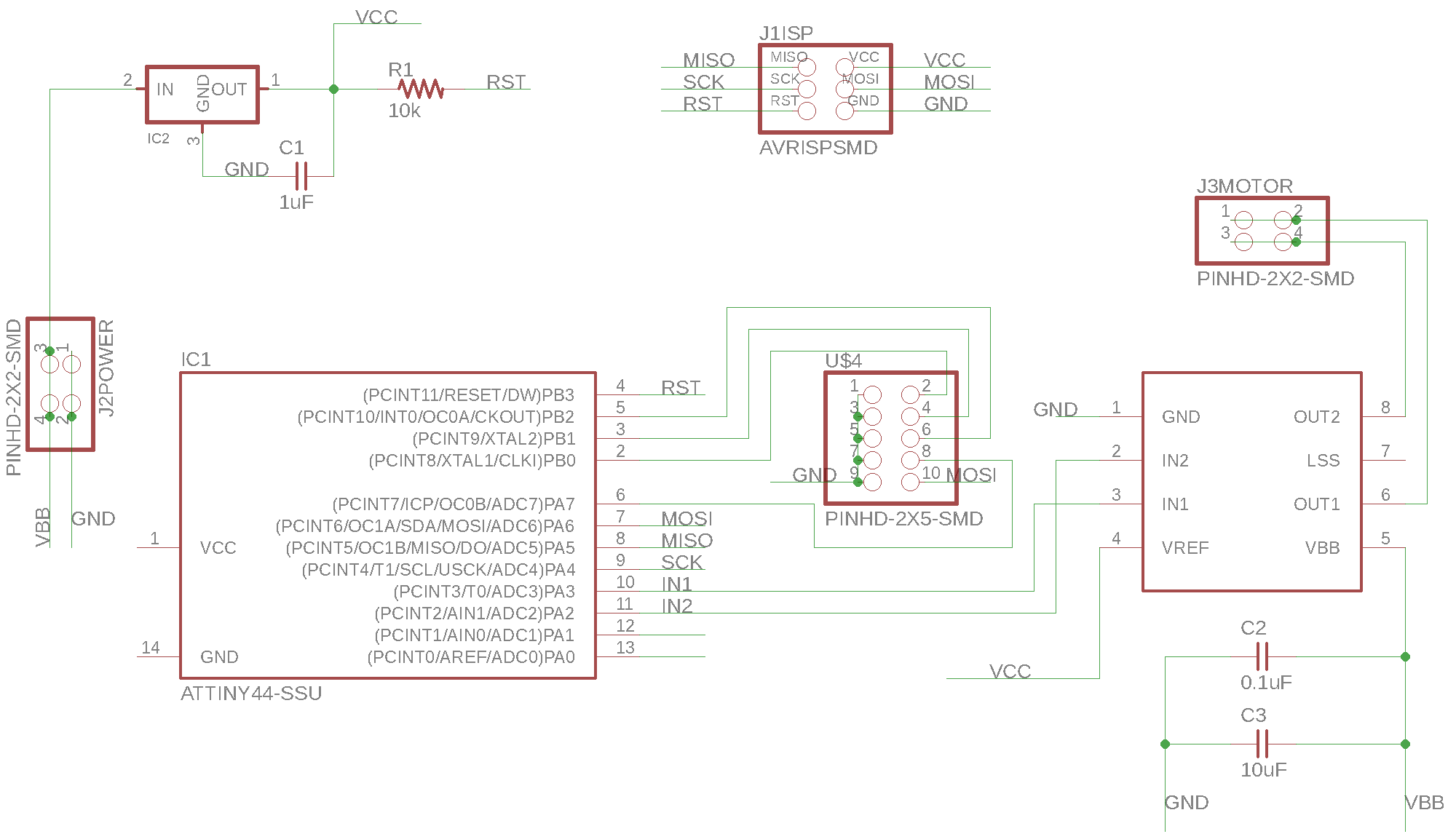
Designing my Board
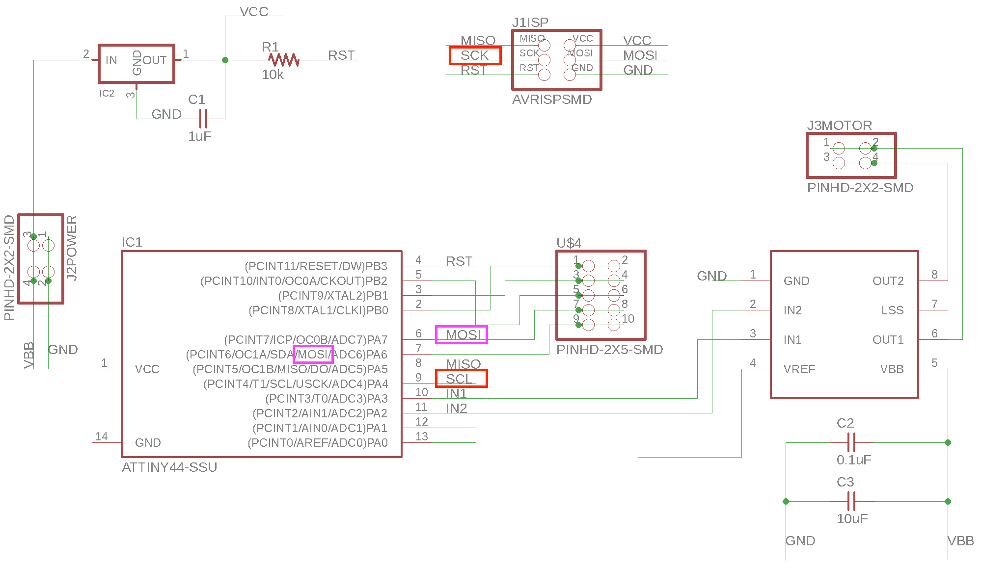
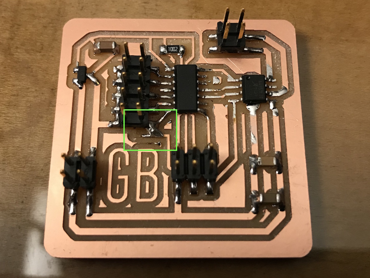
I started off by taking a look at Neil's Hello DC board. Once I had my mind wrapped around what was going on there, I moved into designing my own version in EAGLE. I started by adding all the components I knew I would need. I also added a 2x5 header to allow me to more easily access some of the unused pins on the ATtiny44 MCU. It turns out this was a crucial addition for later debugging (see below). In designing my schematic, I made two critical errors. One was I mislabeled a net as "SCL" when it should have been "SCK" and so my SCK pin on my ISP header was not connected to anything. Also, I mislabled the net on pin PA7 as MOSI, when, in fact, PA6 is the MOSI pin.
Each of these errors lead to the following error when I later tried to program the board:
avrdude: initialization failed, rc=-1
         Double check connections and try again, or use -F to override
         this check.
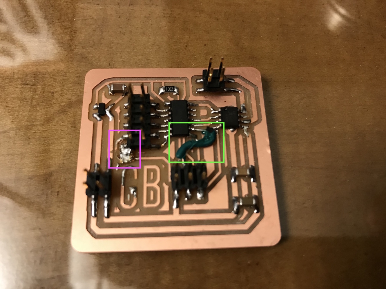
I was able to fix these problems without re-milling the board by jury rigging some fixes. I soldered a wire from the SCK pin on the ISP header to pin PA4 where it was supposed to go, and I used a utility knife to sever the trace erroneously connecting MOSI to PA7, and then solder in a piece of wire from MOSI to PA6. It's ugly, but it works.
After catching these errors, I fixed my EAGLE design file, as reflected in this schematic:
Milling the Board
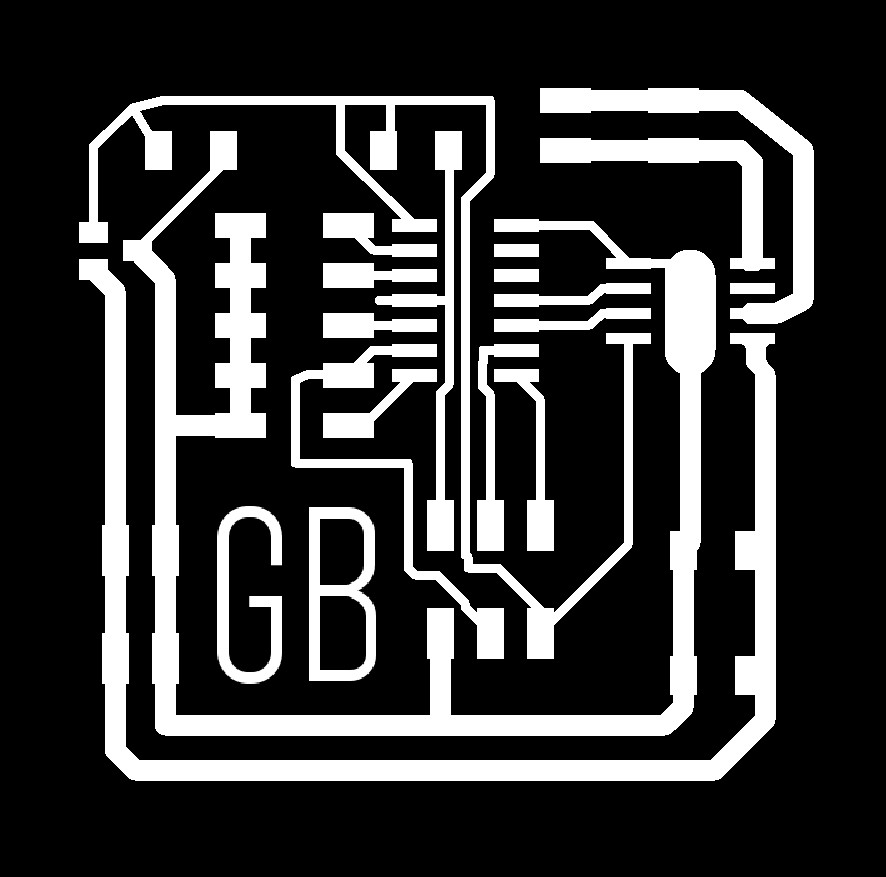
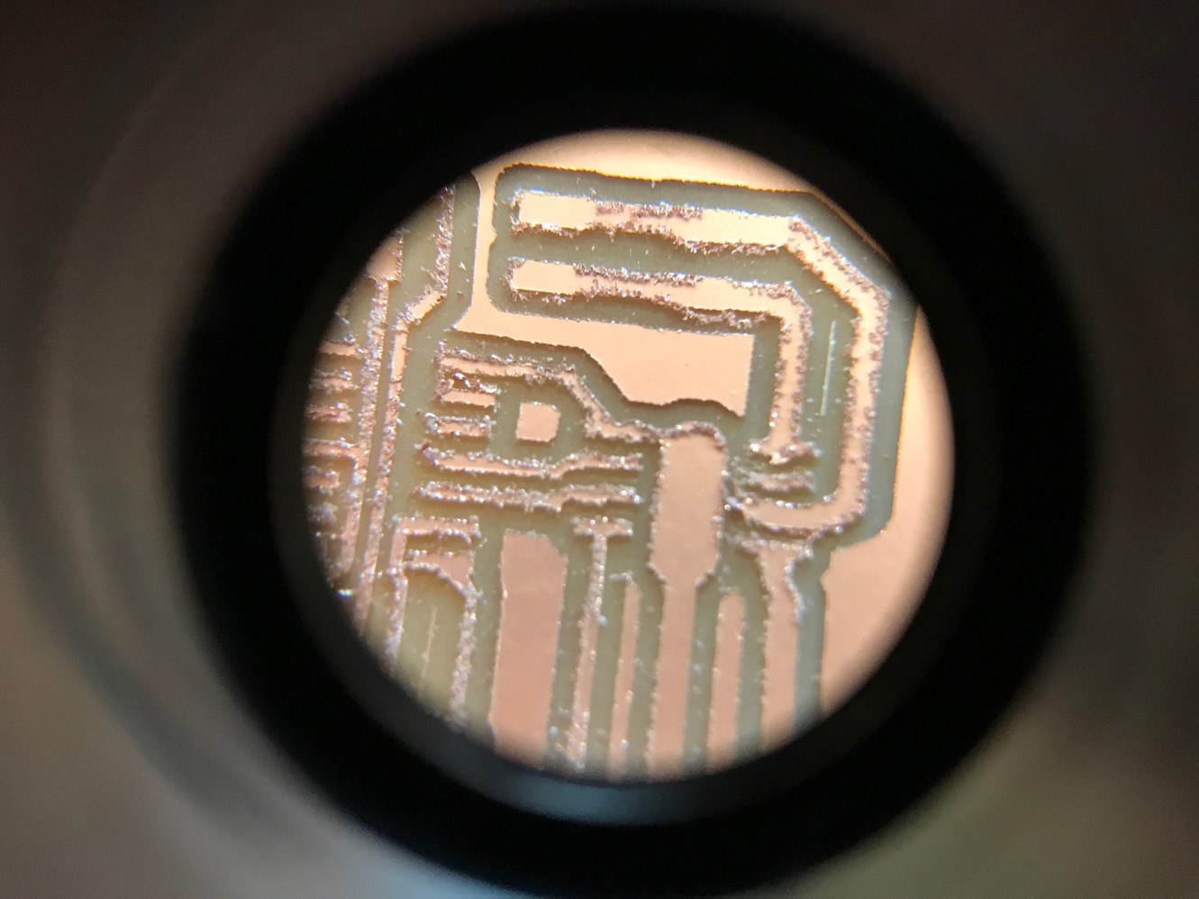
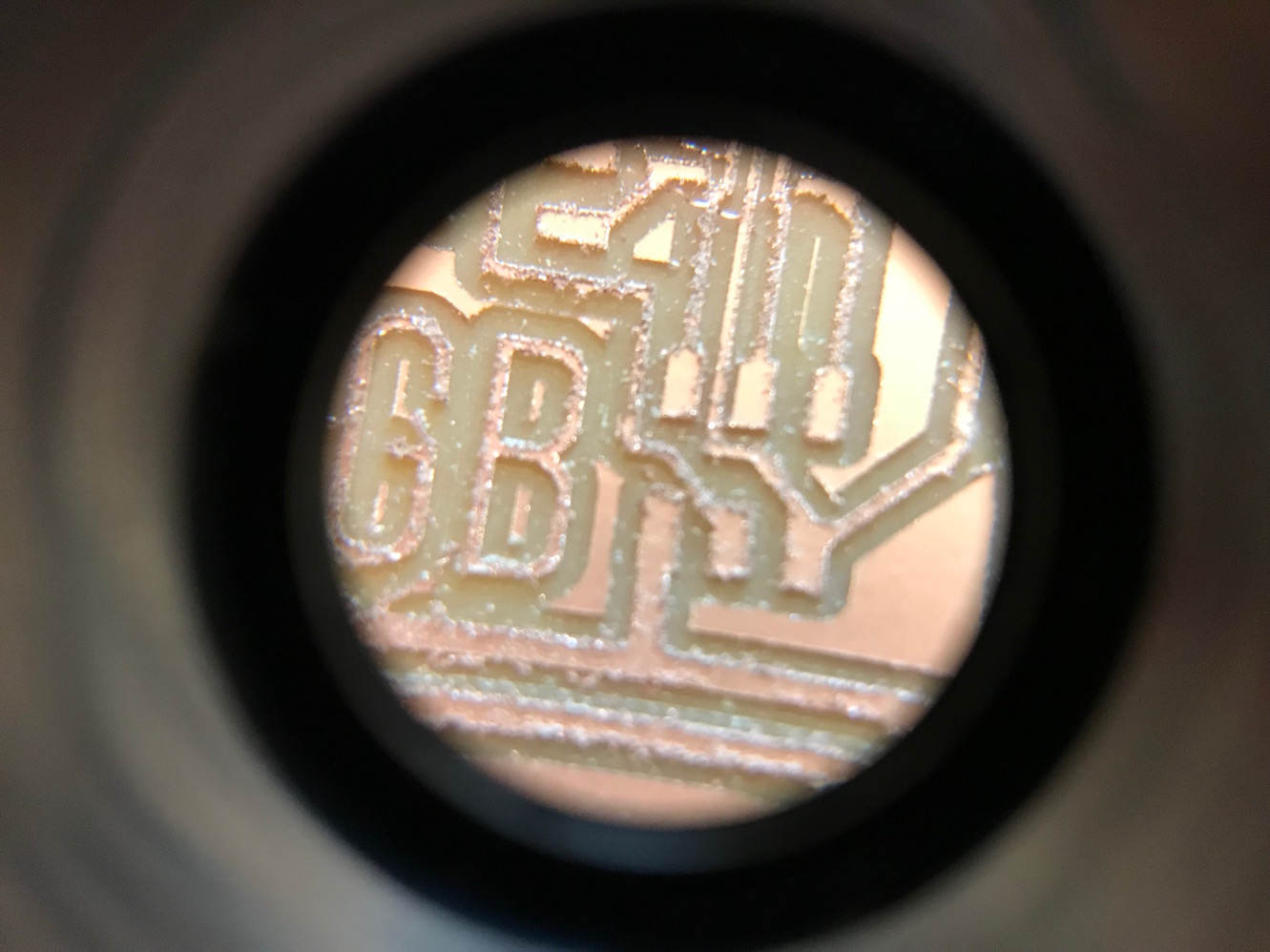
EAGLE for Mac OS (version 8.6.3) still seems to have the scaling error when using the File > Export > Image tool. It scales the .png file up by about a factor of 2, which of course makes the .png file useless for milling. So I brought the EAGLE .brd and .sch files over to a computer with Ubuntu and exported the images there. I did a little touch up within GIMP (e.g. adding my initials and rounding the corners of the interior milling path):

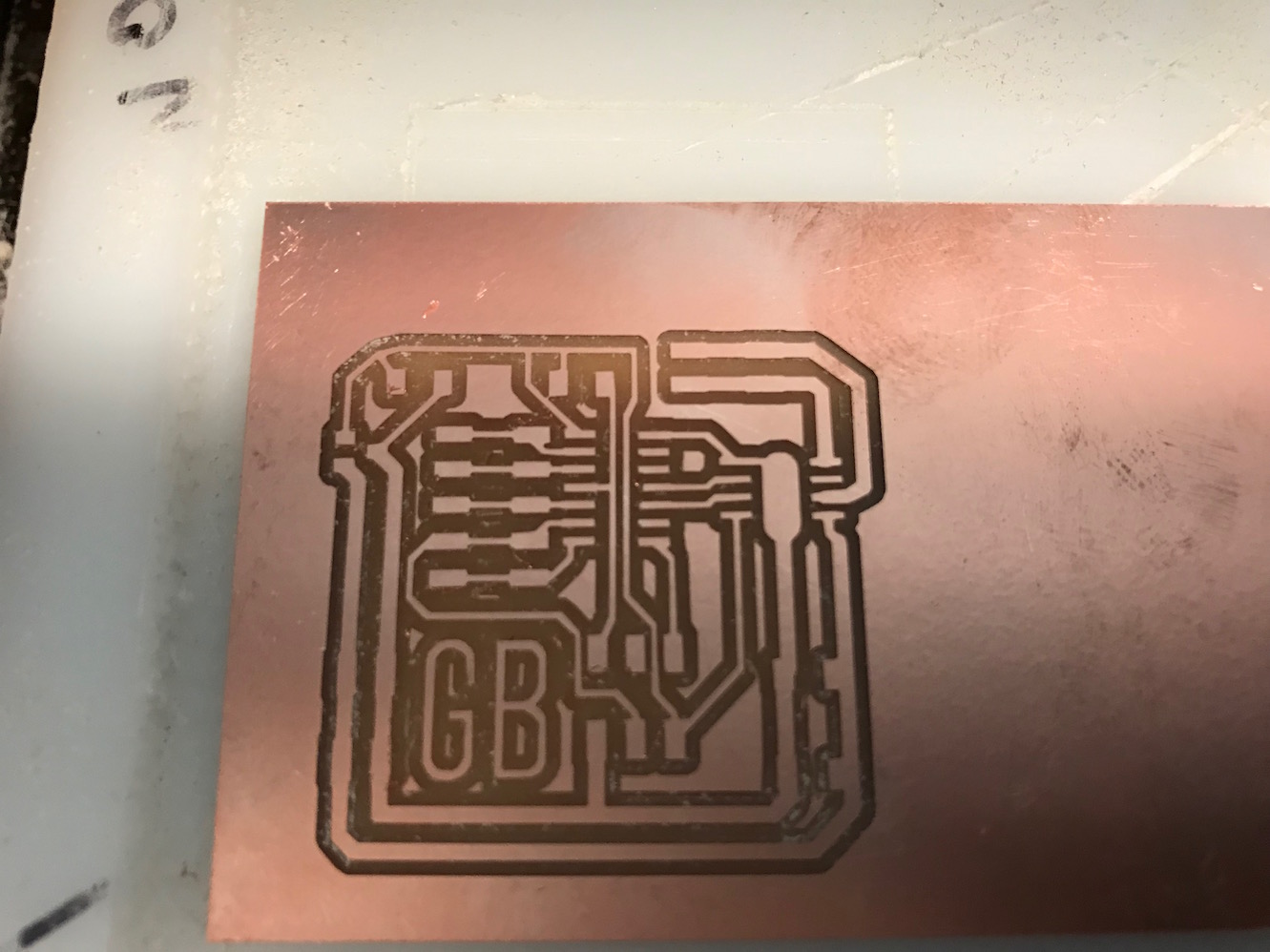
I brought these into Mods and milled the board. The first time, to very poor results do to a worn-out 1/64" milling bit:
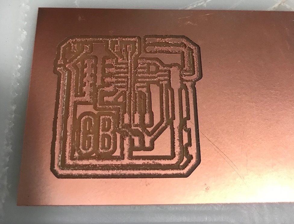
The board was not salvageable, but it made a nice example of what milling with a worn-out bit looks like! Anyway, I replaced the bit and re-ran the job, to much better effect:
I soldered all the components on the board, and, as noted above, when I tried to program it, I could an avrdude error initialization failed, rc=-1. This is how I discovered the errors detailed above, and then jury rigged my work-around modifications to the board to get it working. Here's the board I was finally able to program:
Programming the Board(s)
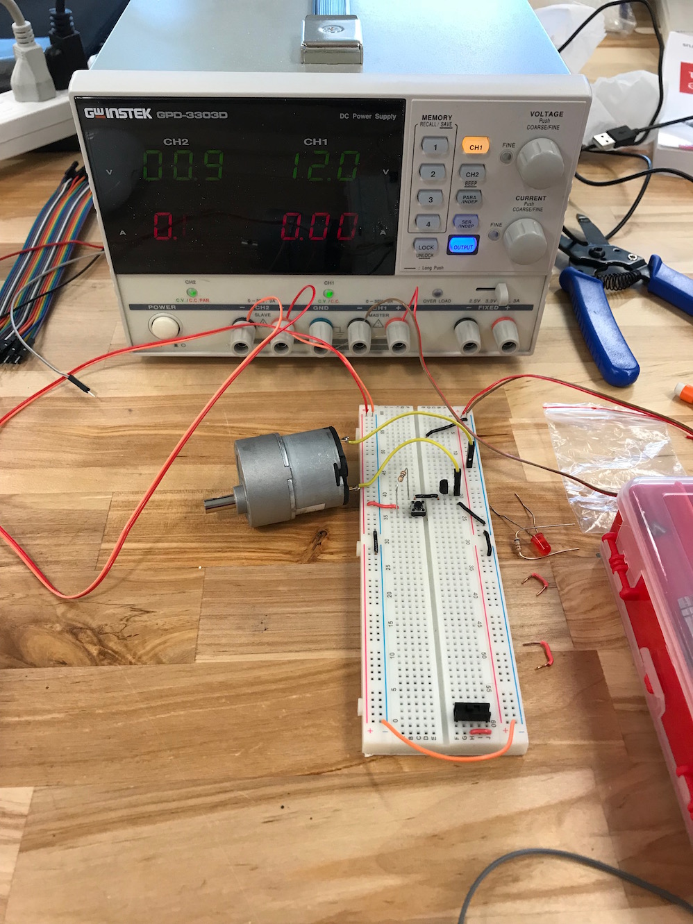
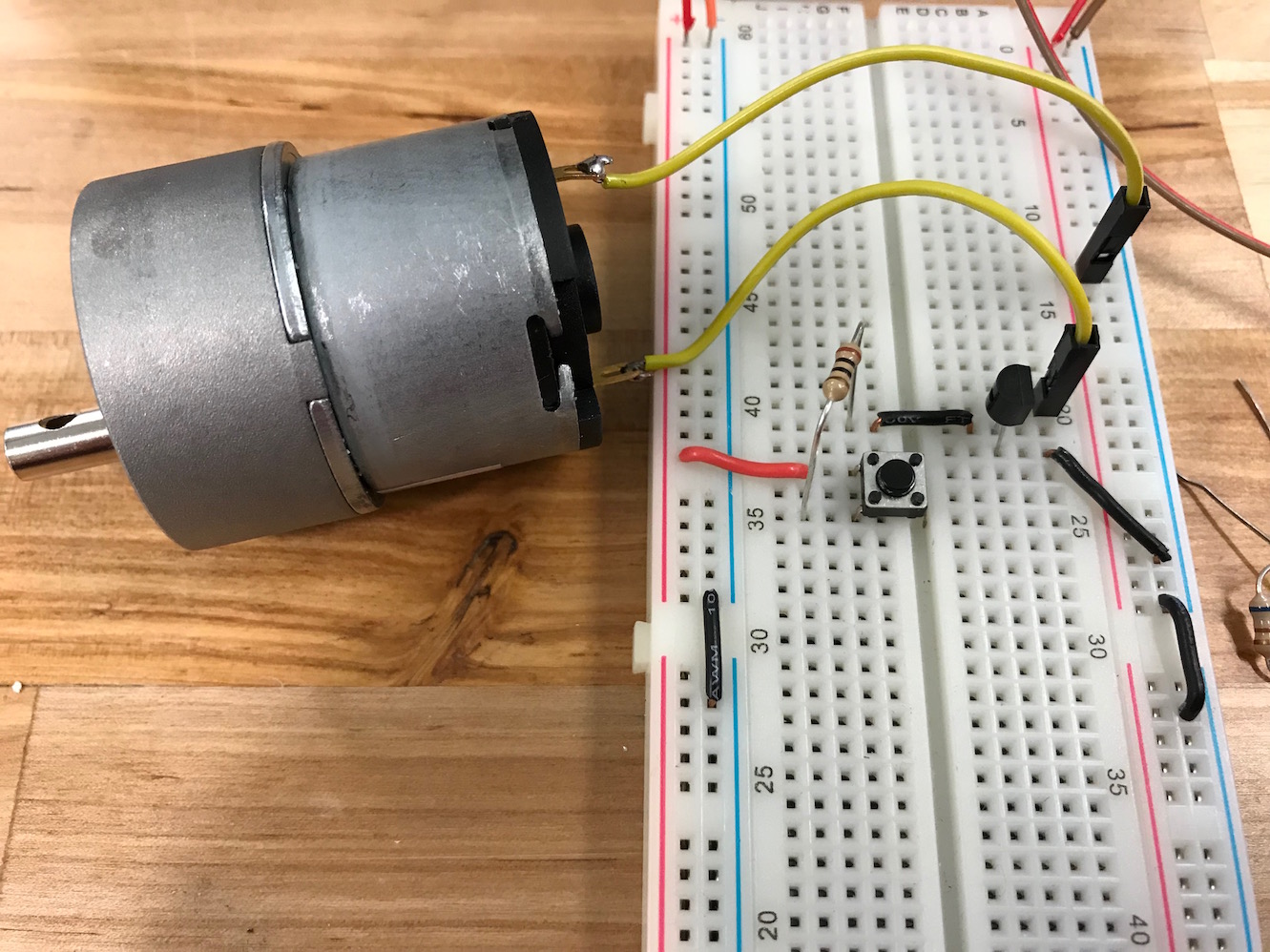
Now that I finally had the boards milled, stuffed, and talking to the computer, it was time to try and drive a DC motor with the boards. I loaded up Neil's code and nothing. With a multimeter I checked the voltages, and basically OUT2 and OUT1 - the two outputs of the A4953 motor driver - were both reading +12V. It makes sense that this wouldn't drive the motor (there's no potential there to drive anything) but I still didn't really understand what was going on. I spent some time with the datasheet, but still couldn't quite pin it down (so to speak). So I decided to go to an even more basic level and just drive the motor on/off using a transistor.
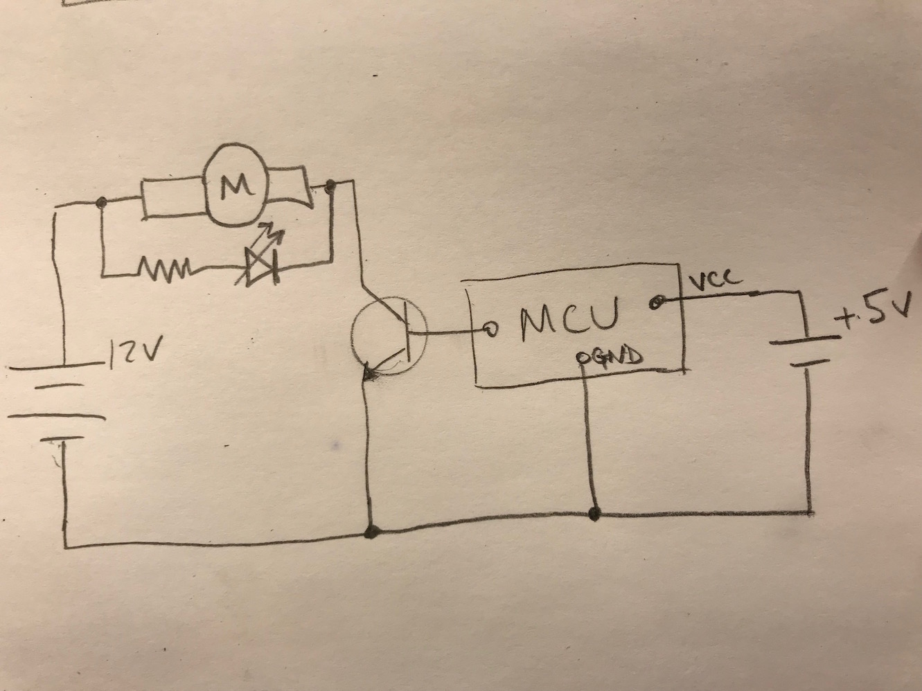
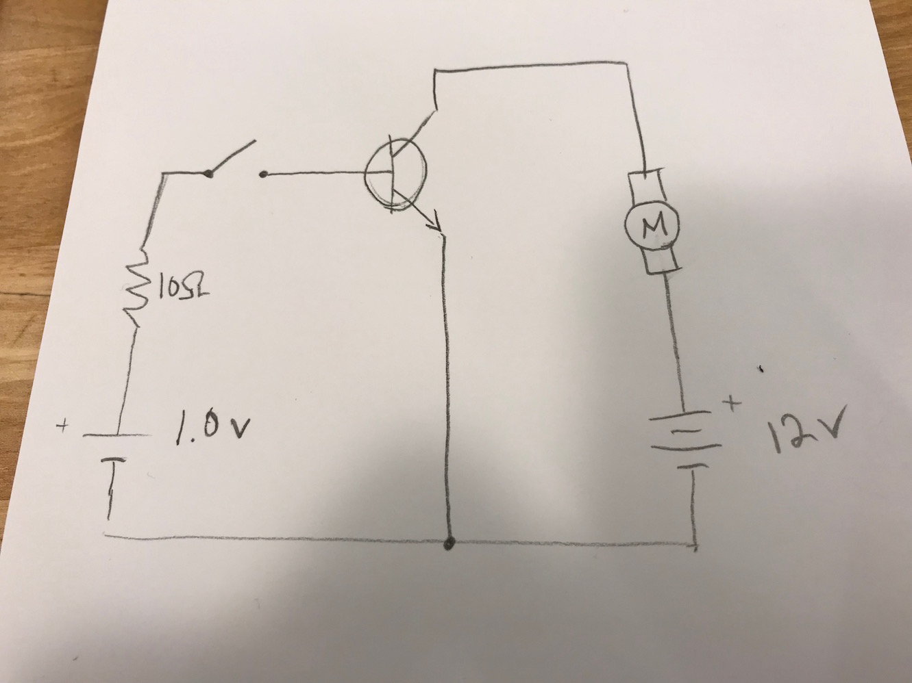
So, I hooked up the circuit, using an NPN transistor I had laying around, and I wrote a simple Arduino script to turn the signal to the transistor on and off:
#define ledPin 10

unsigned long previousMillis = 0;
unsigned long currentMillis = 0;
bool ledOn = false;

void setup() {
  // put your setup code here, to run once:
  pinMode(ledPin, OUTPUT);

}

void loop() {
  // put your main code here, to run repeatedly:
  currentMillis = millis();
  if (currentMillis - previousMillis > 500){
    previousMillis = currentMillis;
    if (!ledOn){
      digitalWrite(ledPin, HIGH);
      ledOn = true;
    }
    else{
      digitalWrite(ledPin, LOW);
      ledOn = false;
    }
  }
}
10_transistor_motor01 from Greg Buckland on Vimeo.
Here's a little voiceover explaining the setup:
11_transistor_motor02 from Greg Buckland on Vimeo.
It's quite basic, but it does prove that my board is working (at least the MCU portion of it).
Next up, I wanted to control the motor speed using pulse width modulation (PWM). I put together a simple circuit with a potentiometer being read in, and that value being used to set the PWM signal to drive the motor at variable speeds.
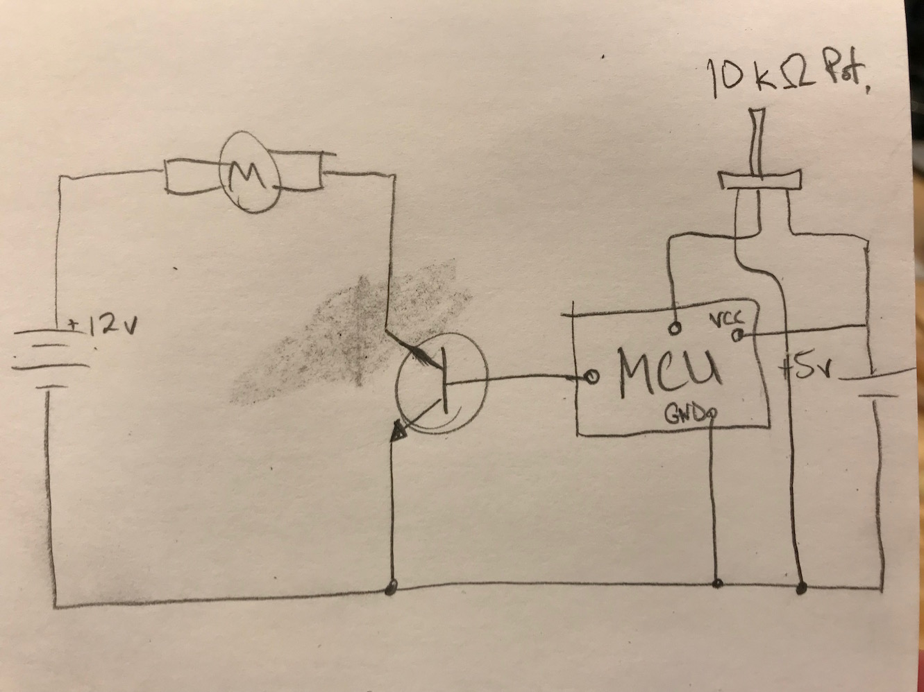
This Arduino script is greatly simplified from one I found here:
#define ledPin 6
#define potPin 7

int potValue = 0;
int pwmOutput = 0;

void setup() {
  // put your setup code here, to run once:

}

void loop() {

  potValue = analogRead(potPin); // Read potentiometer value on potPin
  pwmOutput = map(potValue, 0, 1023, 0 , 255); // Map the potentiometer value from 0 to 255
  analogWrite(ledPin, pwmOutput); // Send PWM signal to ledPin

}
13_pwm_motor_demo from Greg Buckland on Vimeo.
Again, it works well, and proves that the MCU is working reasonably well. Where I'm breaking down is the A4953 motor driver. I think the key here will be to spend more time with the datasheet.
Addendum: I figured out what was wrong in Week 12: the pins I had hooked up to the A4953 (pins PA2 and PA3) are not capable of producing Pulse Width Modulation (PWM), and so they aren't able to drive the motor in any way other than binary on/off (i.e. they can't control speed). I still don't understand exactly why Neil's code didn't work. Still a head scratcher, but I very clearly got an output board working well in Week 12. Check that out if this doesn't quite meet the criteria for success in this week's assignment.
Design Files
DC motor board file (.BRD file)
DC motor schematic file (.SCH file)
Traces and interior GIMP file (.XCF file)