Week 04: Electronics Production
- characterize the specifications of your PCB production process
- Make an in-circuit programmer by milling the PCB (program it, so that you can use it to program your board in Electronics Design week, and in other weeks)
- Optionally, trying other processes
Learning outcomes:
- Describe the process of milling, stuffing, de-bugging, and programming
- Demonstrate correct workflows and identify areas for improvement if required
Have you:
- Shown how you made and programmed the board
- Explained any problems and how you fixed them
- Included a 'hero shot' of your board
My Process
Background
I have a little bit of CNC experience, but I've never used such a small, precise mill, and I've never milled PCBs (printed circuit boards) before. I have experience with through-hole soldering, but never surface-mount and never such small components. I have a little bit of experience with Arduino and microcontrollers, but I've never used an ISP (in-system programmer) before.
PCB Milling
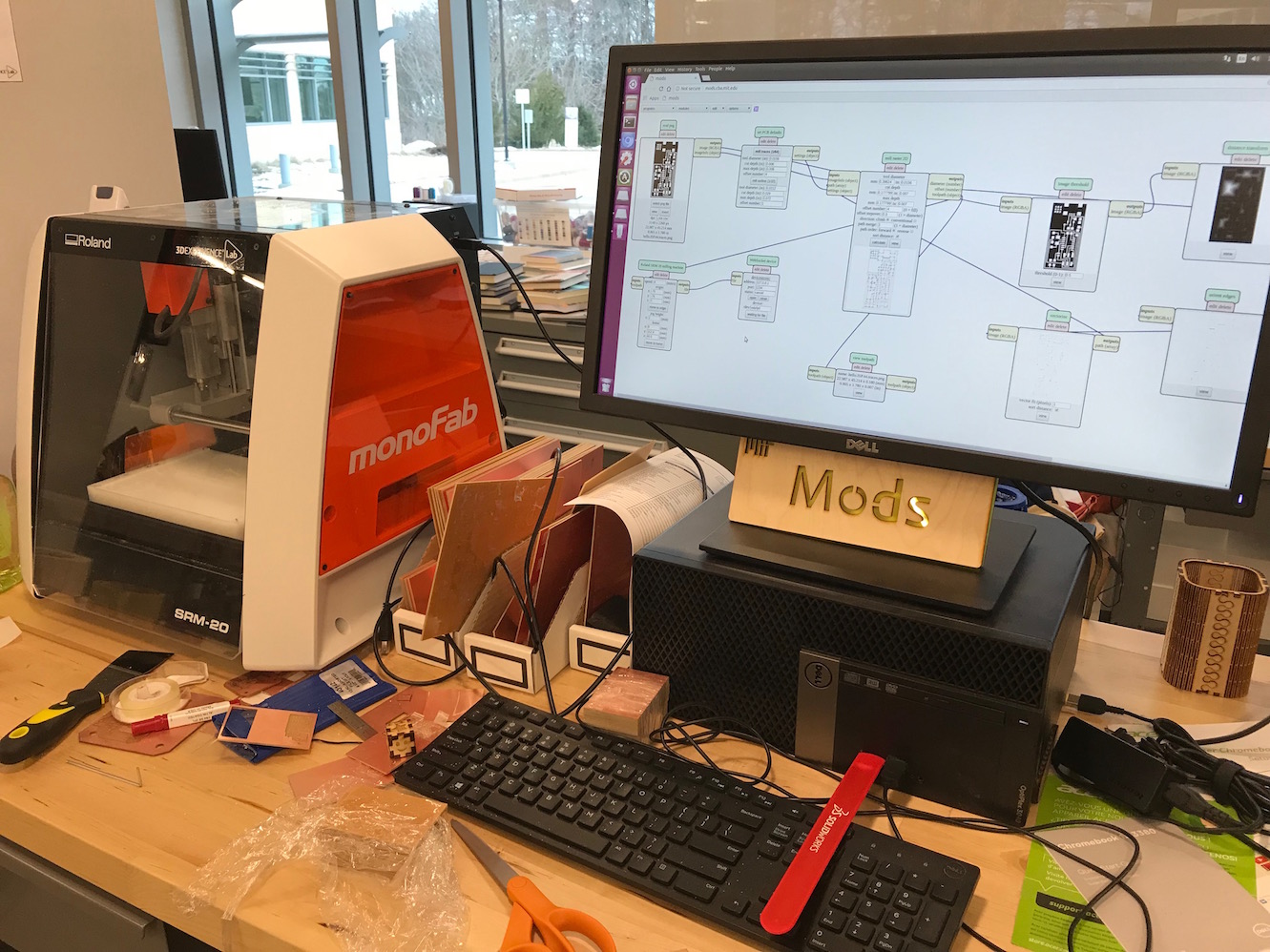
It has been a fun (though at times exasperating) experience getting my PCB milled. I have a Roland monoFab SRM-20 at my Fab Lab at Lena Park (the same as we have at the Dassault lab), and so I thought I'd try to get it up and running. After many hours of headbanging, and a great deal of frustration at the Roland DG corporation, I was never able to get the drivers correctly installed on my windows machine (or get mods running on the windows machine). This is an area I'd still like to resolve in the future. Instead, I decided to return to Dassault and do the milling there.
Most of our class (including me) decided to go with the FabISP board using the ATtiny44 microcontroller. We got our Roland SRM-20 up and running with mods on an Ubuntu system (try as we might, we couldn't get it to work in Windows).
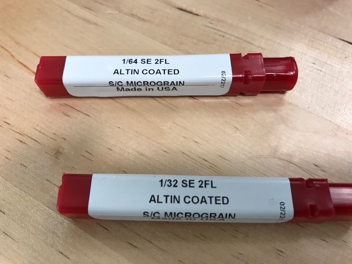
We grabbed the appropriate files for our board, and ran them through Mods. First we selected the 1/64" mill bit for the traces file.
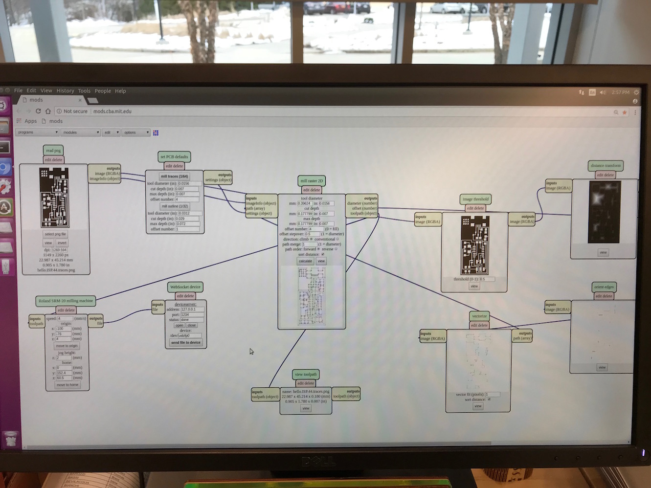
We selected the appropriate mill bit (in this case 1/64th, flat end, with 2 flutes).
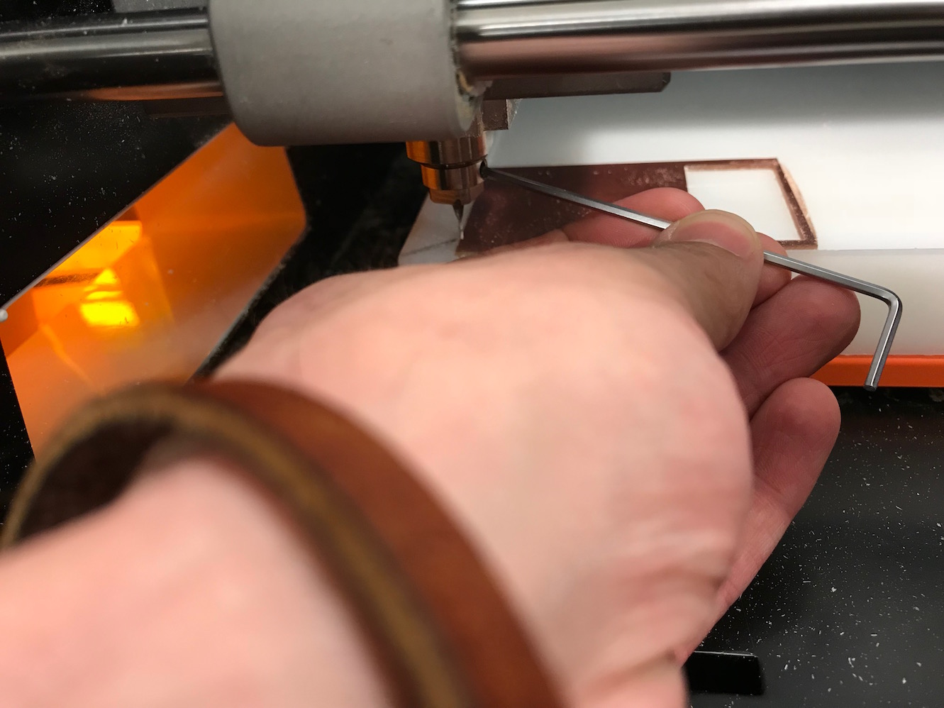
We loaded in the 1/64" mill bit, brought the bit to the "origin" of our workpiece (lower left corner), and then "zeroed" the bit. In other words, we brought the z-axis close to the surface (about 2 or 3mm above it), and then carefully loosened the collet set-screw and gently placed the millbit flat on the workpiece before re-tightening the collet.
With the millbit set, and the file prepped in Mods, we were ready to mill!
After milling the traces, we swapped the bit for a 1/32" bit, loaded the file for the outline of the board interrior, and cut the board outline out.
Stuffing the Board
I then collected my milled board (which I didn't photograph - d'oh!) and assembled my components.
- 1 ATTiny 44 microcontroller
- 1 Capacitor 1uF
- 2 Capacitor 10 pF
- 2 Resistor 100 ohm
- 1 Resistor 499 ohm
- 1 Resistor 1K ohm
- 1 Resistor 10K
- one 6 pin header
- 1 USB connector
- 2 jumpers - 0 ohm resistors
- 1 Crystal 20MHz
- two Zener Diode 3.3 V
- one usb mini cable
- one ribbon cable
- two 6 pin connectors
Source: Fab Academy Tutorials - Week 04
I assembled all my components together and taped them to a sheet of paper with labels. I brought enough components to make about 3 boards (just in case I screwed something up and/or lost a component or two).
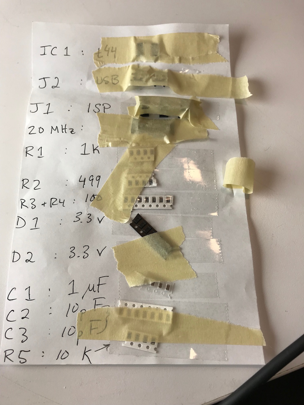
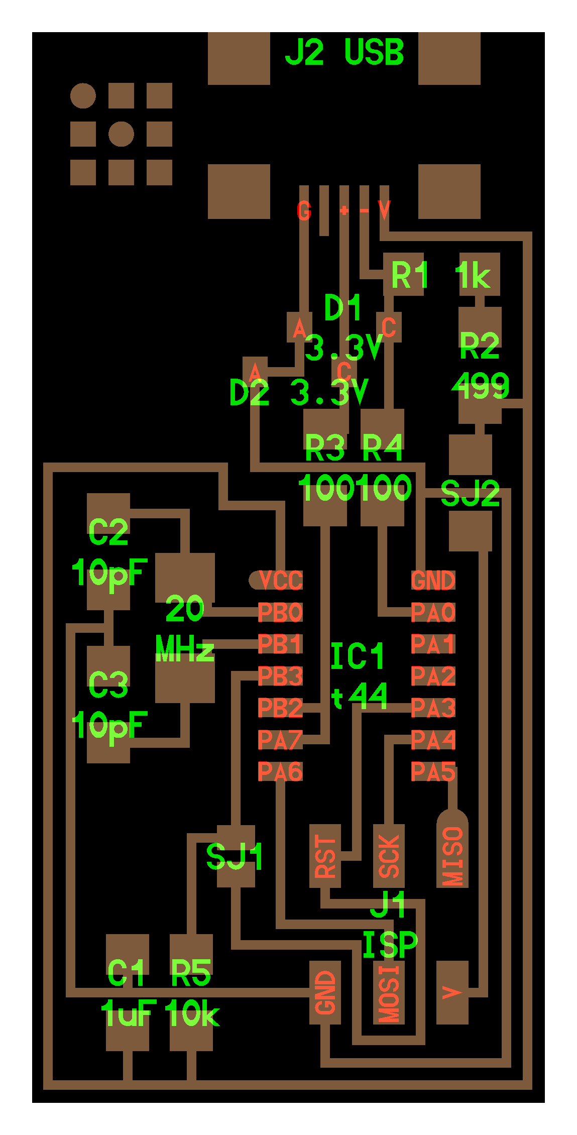
And I used the board layout diagram as a guide to determine where all the components would go.
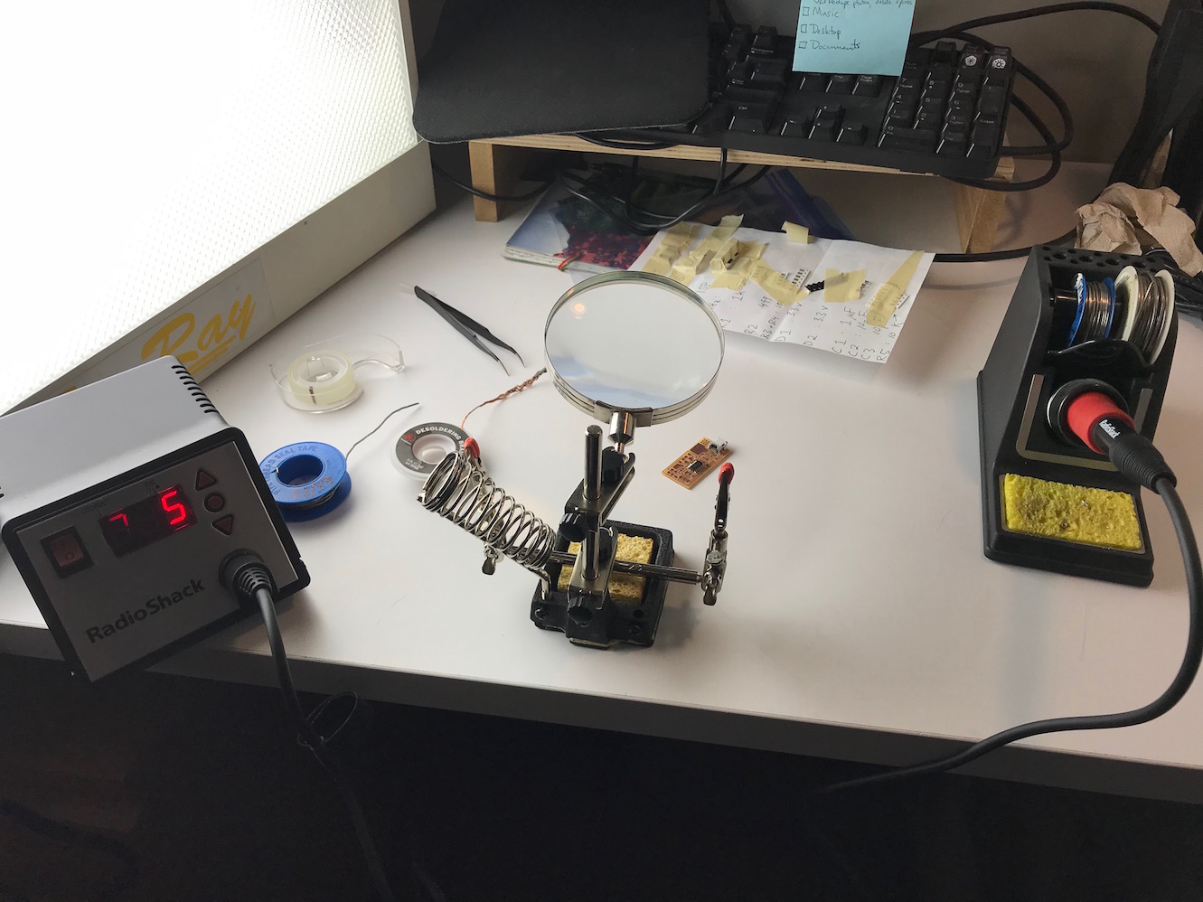
I brought the components home (it was closing time at the Dassault lab) and got out my trusty soldering iron/helping hands/multimeter combo.
As suggested by our instructor, Luciano, I began with the trickiest components first - the microcontroller itself and the USB connector jack.
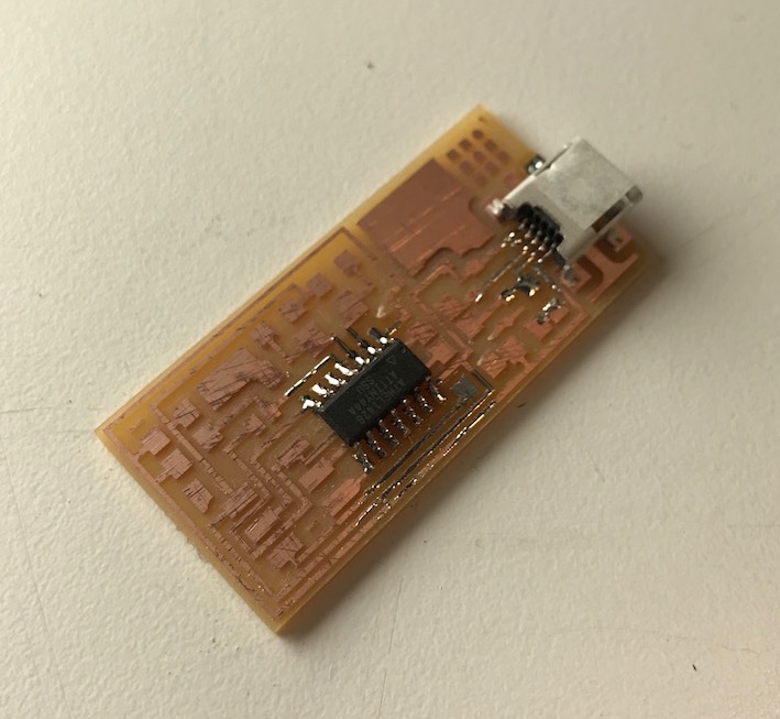
I then worked outward from the middle, adding components to the board in order of component height. (I.e. I left the 6-pin header until last so it didn't get in the way of soldering other components). I used the "tack-one-corner" approach for most componenets. For elements with many pins (e.g. IC, USB jack, header), I globbed excess solder across all the connectors and then used solder braid to wick away the excess, leaving nice, pretty joints.
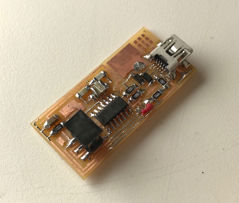
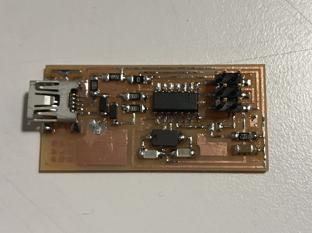
A few notes here: I neglected to bring home any 0 ohm resistors to use as jumpers, so I just used a small piece of wire instead. And more critically, I mistakenly picked a 20 MHz resonator (shown here above) instead of a 20 MHz crystal. As a result, my board did not work at first (more on this later).
Programming my Board
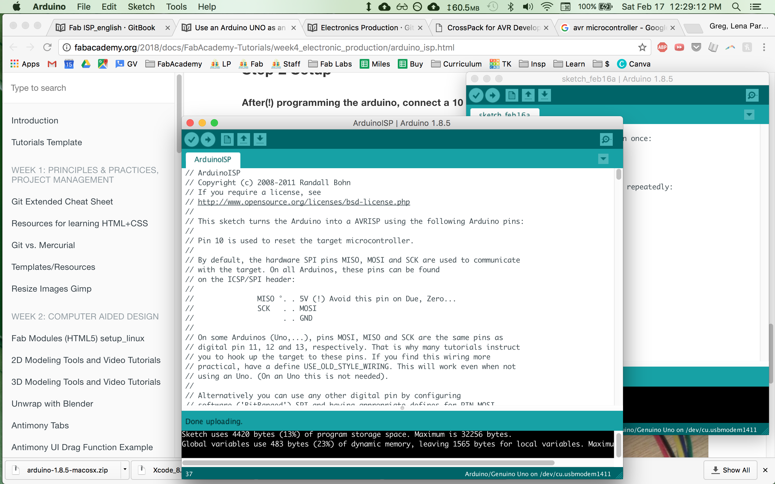
With my board stuffed and soldered, I was ready to give a go at programming, or so I thought. I didn't have another ISP to program it with, but thankfully, I did have an Arduino Uno along with the handy tutorial on how to use an Arduino as an In-System Programmer. I jumped right in and uploaded the ArduinoISP sketch to my Uno.
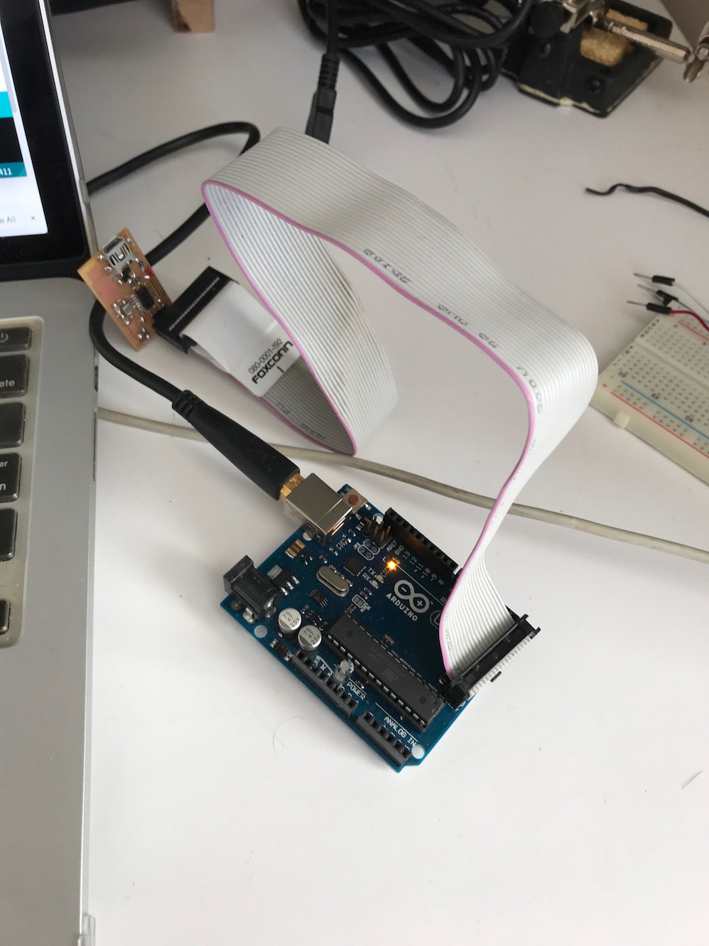
I installed the appropriate software - it took a little doing to find a version of XCode that worked with my mac os system (note for future Fabbers: Xcode 8.3 will run on mac os 10.11.6 "el capitan" and can be found at the Apple developer downloads page). I then connected the Arduino to my ISP via a ribbon cable. I spent a bit of time with my multimeter set to continuity testing to check the Arduino pinout on the 6-pin header, and everything seemed to be in order.
I edited my Makefile to accomodate the ArduinoISP, including the USB port it was operating on. I checked all the cables, passed the "smoke test", and began to run the commands.
make clean outputted a lovely, correct response:
rm -f main.hex main.lst main.obj main.cof main.list main.map main.eep.hex main.elf *.o usbdrv/*.o main.s usbdrv/oddebug.s usbdrv/usbdrv.s
make hex outputted a mostly correct response:
    avr-gcc -Wall -Os -DF_CPU=20000000	 -Iusbdrv -I. -DDEBUG_LEVEL=0 -mmcu=attiny44 -c usbdrv/usbdrv.c -o usbdrv/usbdrv.o
    avr-gcc -Wall -Os -DF_CPU=20000000	 -Iusbdrv -I. -DDEBUG_LEVEL=0 -mmcu=attiny44 -x assembler-with-cpp -c usbdrv/usbdrvasm.S -o usbdrv/usbdrvasm.o
    avr-gcc -Wall -Os -DF_CPU=20000000	 -Iusbdrv -I. -DDEBUG_LEVEL=0 -mmcu=attiny44 -c usbdrv/oddebug.c -o usbdrv/oddebug.o
    avr-gcc -Wall -Os -DF_CPU=20000000	 -Iusbdrv -I. -DDEBUG_LEVEL=0 -mmcu=attiny44 -c main.c -o main.o
    main.c:88:13: warning: always_inline function might not be inlinable [-Wattributes]
     static void delay ( void )
                 ^
    avr-gcc -Wall -Os -DF_CPU=20000000	 -Iusbdrv -I. -DDEBUG_LEVEL=0 -mmcu=attiny44 -o main.elf usbdrv/usbdrv.o usbdrv/usbdrvasm.o usbdrv/oddebug.o main.o
    rm -f main.hex main.eep.hex
    avr-objcopy -j .text -j .data -O ihex main.elf main.hex
    avr-size main.hex
   text	   data	    bss	    dec	    hex	filename
      0	   2002	      0	   2002	    7d2	main.hex
Note: make hex does seem to throw a gcc debugging error, but it turns out this was not a problem (see below).
But when it came time to run make fuse I ran into trouble.
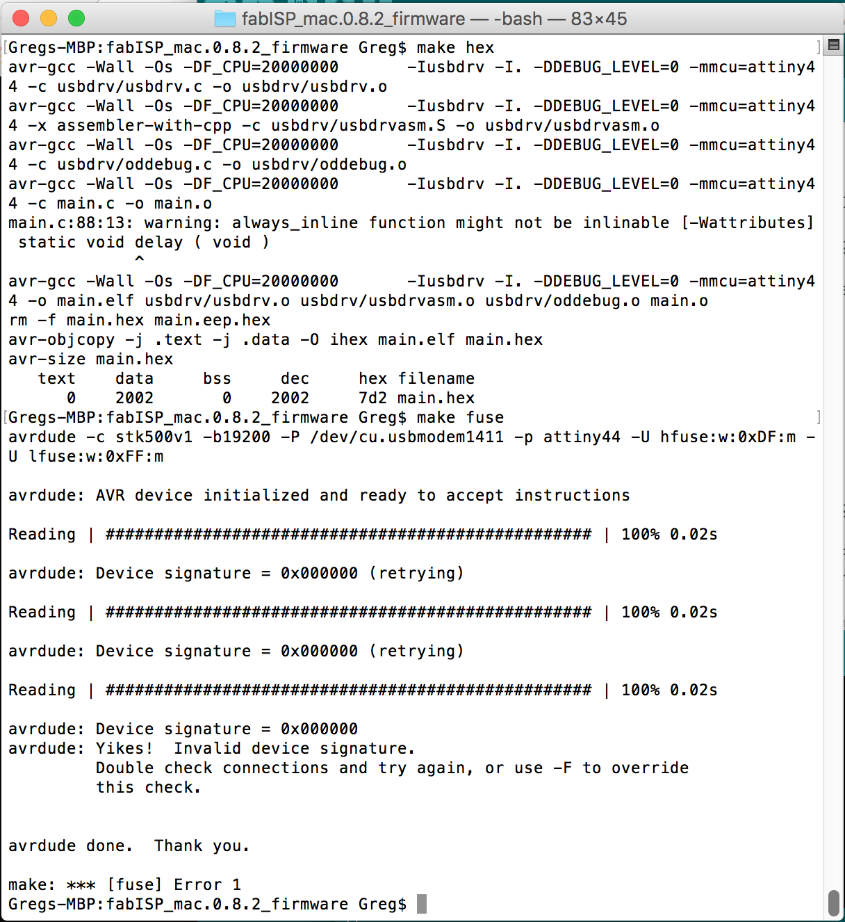
Along with the other output in the image above, I received the following error message.
    avrdude: Device signature = 0x000000
    avrdude: Yikes! Invalid device signature.
            Double check connections and try again, or use -F to override this check.


    avrdude done. Thank you.

    make: *** [fuse] Error 1
I did some googling and learned that this essentially means that the board-to-be-programmed, a.k.a. the "target board" (in this case my FabISP-to-be) was not being seen by the ISP (in this case my arduinoISP). As part of my debugging process, I wrote a quick blink sketch to make sure my Arduino was functioning properly. It probably belies my state of mind at the time that I wrote an SOS blink sketch.
I already knew that my board probably wouldn't work because of the 20 MHz resonator I mistakenly picked and soldered (instead of the 20 MHz crystal that was supposed to be there). When I found this near the top of my google search:
All 0s out all 1s indicates wiring problem, or target device is set to use a crystal but isn't connected to one (which renders it inoperative)
I took it as a sign that I needed to swap my resonator for a crystal, which had to wait until I got back to the Dassault lab (my local electronics shop did not have 20 MHz crystals in stock).
Debugging
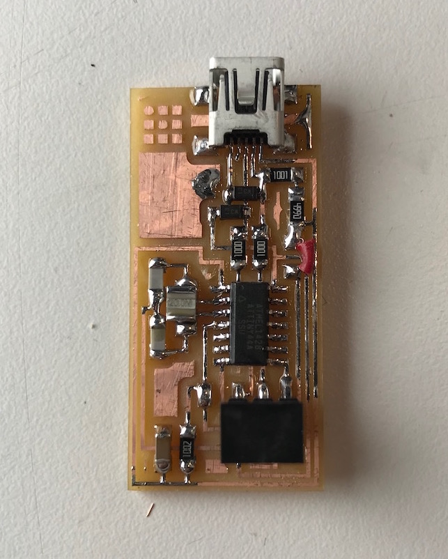
Now that my board was stuffed and soldered but wasn't taking the programming, it was time to debug. The first thing I did was swap out the resonator and replace it with a crystal. I used the focused heat gun technique that Neil showed us in lecture, holding the compnonent to be removed with tweezers and heating the solder until the board dropped away. I also replaced my little wire jumper with a 0 ohm resistor, and visually inspected all my traces and connections. I used solder braid to wick away some gloopy excess solder and reflow a couple joints that didn't look great. The board then looked visually better.

Now that it was cleaned up a bit, and the crystal was installed, I decided to try again to program it with the ArduinoISP. I hooked them all up carefully, and again ran make clean, make hex, and make fuse. Again, clean and hex worked fine, but fuse was still throwing the "Yikes! Invalid device signature" error. Ugh.
Well, we decided, maybe the ArduinoISP just doesn't work right. So we grabbed the lab's Atmel-ICE Basic in-system programmer and debugger. This worked even less well - we couldn't get the Makefile to even recognize the programmer. After much googling, it turns out mac os doesn't play well with Atmel-ICE (there are some instructions and github projects to get it to work, but we weren't ready to go down those paths).
I took a step back and decided to follow the Troubleshooting short circuits directions in the tutorial. I followed the steps, completing a visual inspection. I further cleaned up a few solder joints. I used a multimeter to test continuity in a variety of places along the board. I could find nothing wrong here (though I am not 100% sure which components should block or allow continuity, e.g. a resistor vs. a capacitor vs. a diode vs. an IC). But anyway, VCC and GND were separated, and seemed to have consistent traces. Also, I knew the board was getting power, because I could power the Arduino via the 6-pin header.
After this thorough check, we tried again with the ArduinoISP. No luck. Yikes! Invalid device signature.

We were running out of things to try, so we decided to try re-wiring the connection between the arduino and the board. I very carefully checked the pinout in the ArduinoISP sketch, and set some wires in place with the following color scheme:
    FUNCTION	     PIN	   COLOR
    // slave reset:  10:	   RED
    // MOSI:         11:	   BLUE
    // MISO:         12:	   YELLOW
    // ground:	    GND:	   GREEN
    // SCK:          13:	   ORANGE
    // VCC:         VCC:       VIOLET
I very carefully ran the wires from the Arduino pins to the 6-pin header on my board.
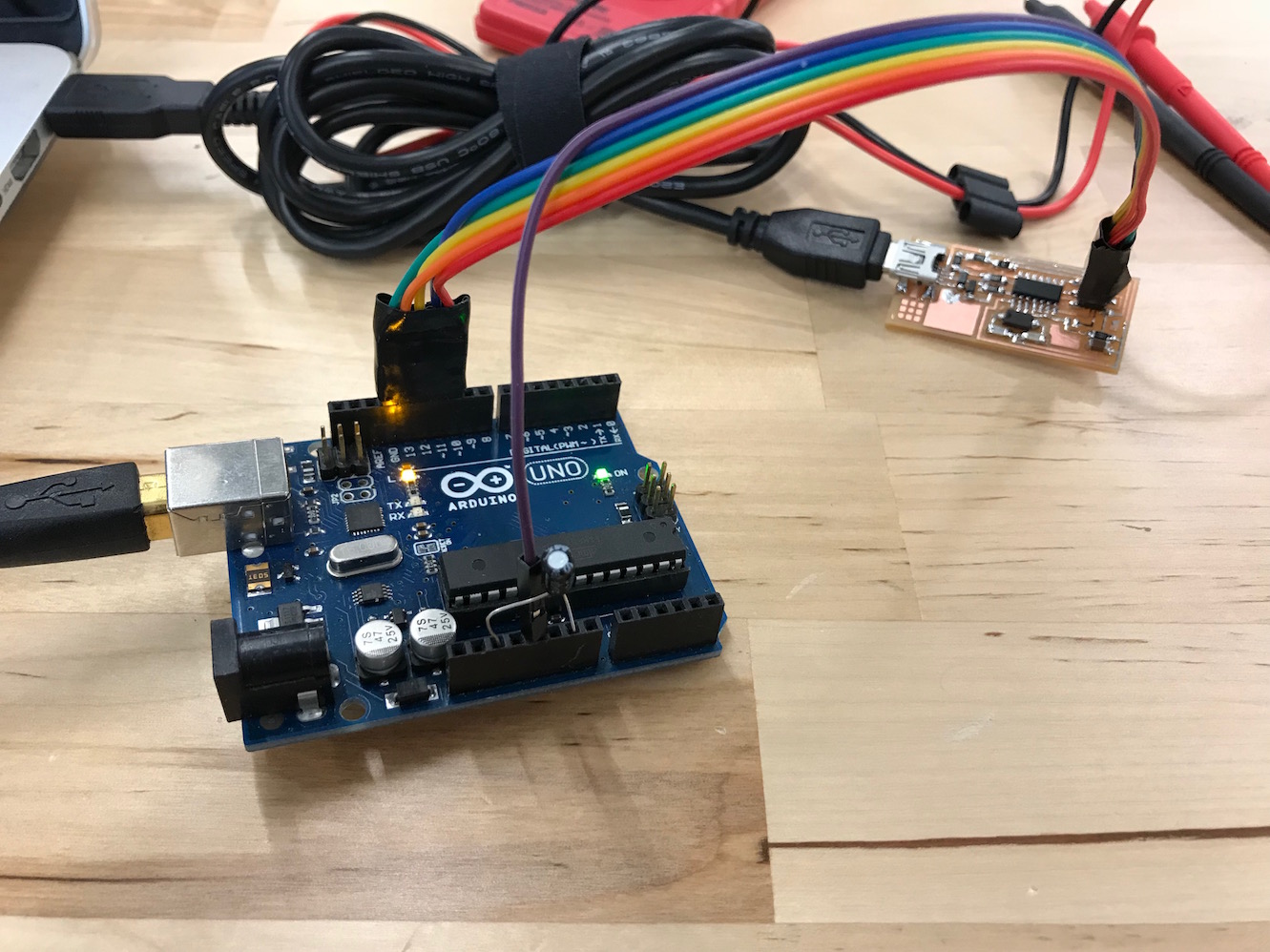
And lo and behold! This time it worked! Running make fuse gave us a lovely output.
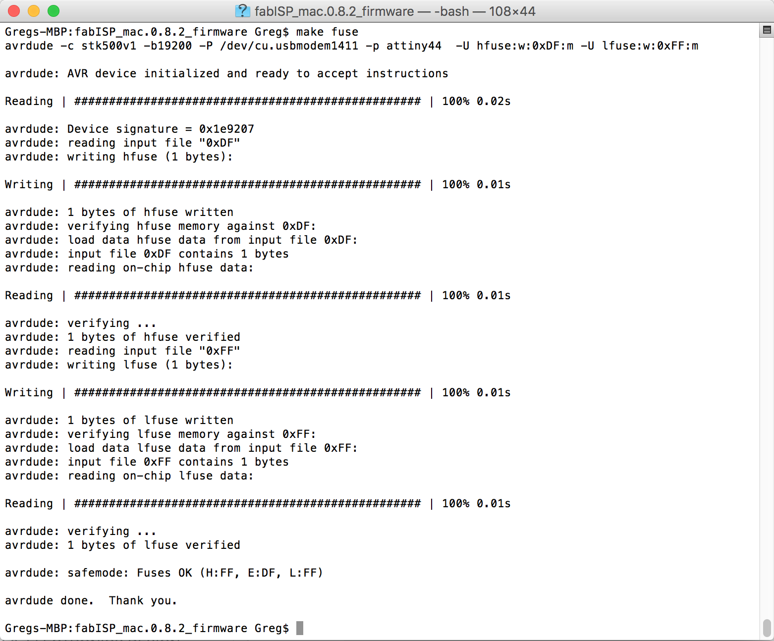
With the fuses set, we ran make program and got the correct output! I was so excited at this point, I neglected to take a screenshot, but the output was just like the output here.
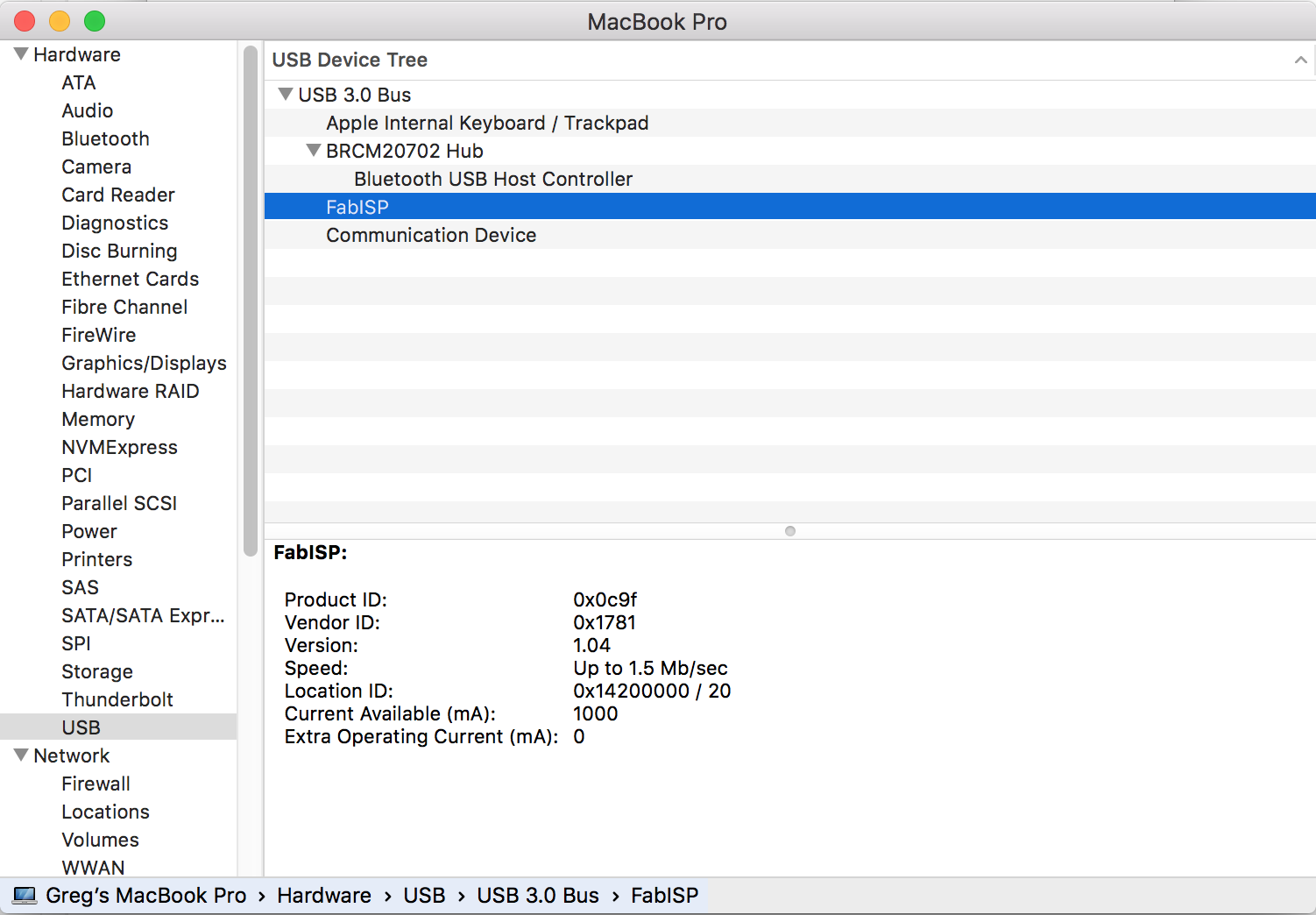
I went to Apple Menu>About This Mac>System Report...>USB and saw this lovely device FabISP recognized by my computer.
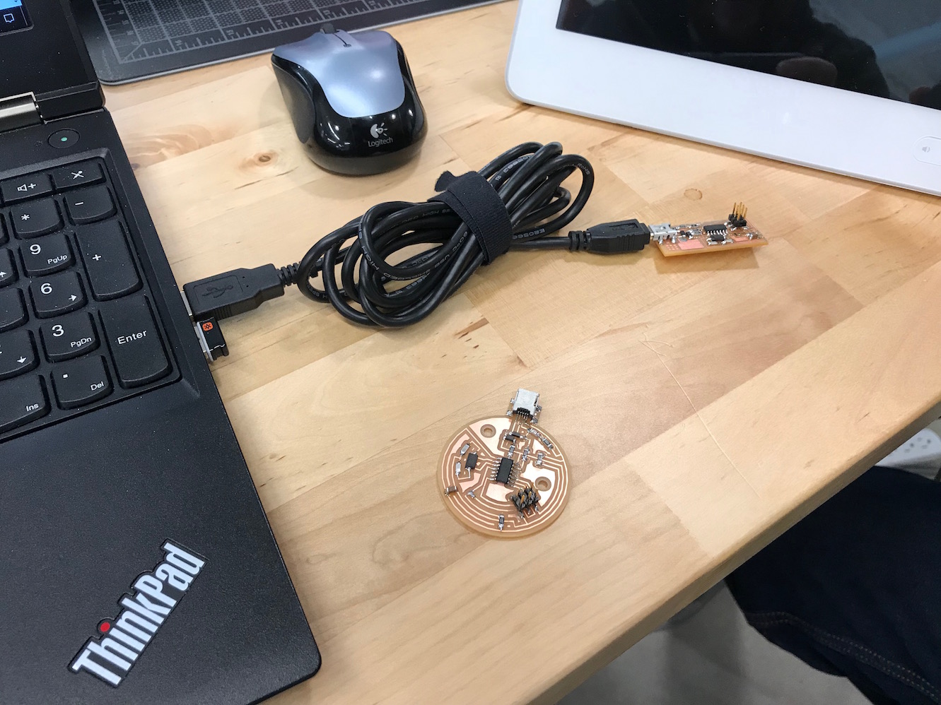
I then went on to remove the solder jumper at position SJ1, as per the instructions. Next, I passed my FabISP to my classmates, and they used it to program their own boards!
Conclusion
This week was challenging. It seemed like every step was full of obstacles and snafus. It took a ton of hours (and several people - thanks Jean Michel!) to get this thing to work, and frankly, I'm not 100% sure how it works or exactly what I'll be using it for. But I trust that's OK for now, and I'll get a better handle on this in future weeks. For now, I'm content to be glad that it works.