Week 06: Electronics Design
- Redraw the echo hello-world board, add (at least) a button and LED (with current-limiting resistor), check the design rules, make it (if you have time this week, test it).
- optional: simulate its operation. Measure its operation
Learning outcomes:
- Select and use software for circuit board design
- Demonstrate workflows used in circuit board design
Have you:
- Shown your process using words/images/screenshots
- Explained problems and how you fixed them, including how you worked with design rules for milling (DRC in EagleCad and KiCad)
- Included original design files (Eagle, KiCad, Inkscape, .cad - whatever)
My Process
Background
I have a little bit of electronics experience, but it's mostly pretty new to me (I still need to be reminded what symbols are what, how polarized components are oriented, and what the components do, etc.) This will be my first foray into EDA (Electronic Design Automation) and any of the CAD tools (EagleCad, KiCad, etc.).
I decided to basically follow the tutorial for this week. I'd like to try KiCad as well, but for now, I'll get started with Eagle.
Getting Started
I downloaded Eagle and booted it up, opening up the hello FTDI board from the tutorials page. I also downloaded and loaded up the fab component library. One snafu: I tried to right-click > save as to get the library, and that didn't work (it grabbed the html file for the github page instead). To fix this, I actually clicked through to github and downloaded the .lbr file from there.
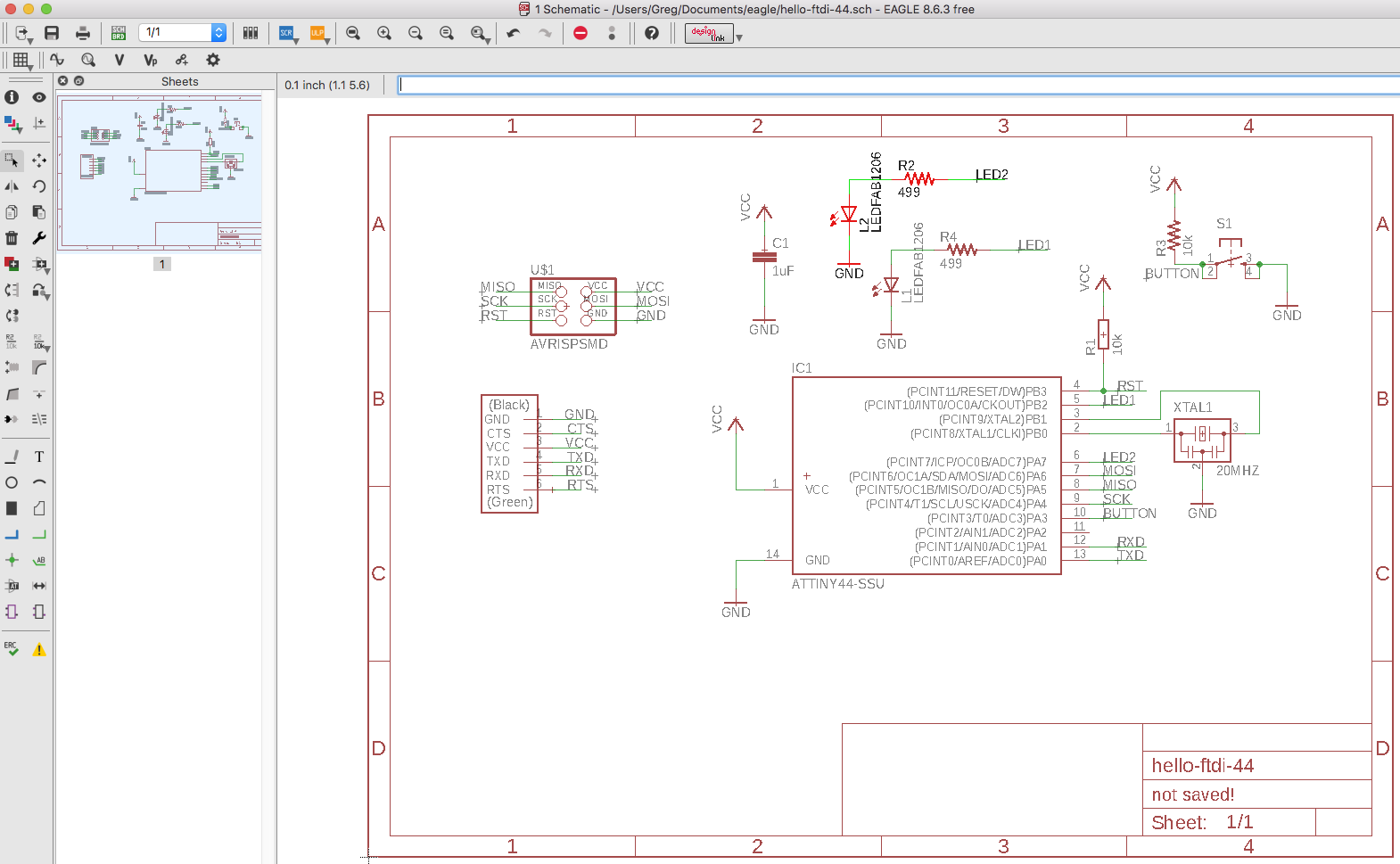
Schematic Design
I essentially followed the tutorial for adding an LED, a button, a few resistors, and their corresponding VCC, GND, and "net" connections. It took a little poking around, but I mostly figured it out (with the help of google). I decided to try for a little "extra credit" and add a second LED / resistor pair on Pin 5. Two LEDs to play with is way more than twice as fun as just having one.
Board Layout
Once I had the schematic up and running, I routed the traces, using the traces shown in the tutorial as a guide.
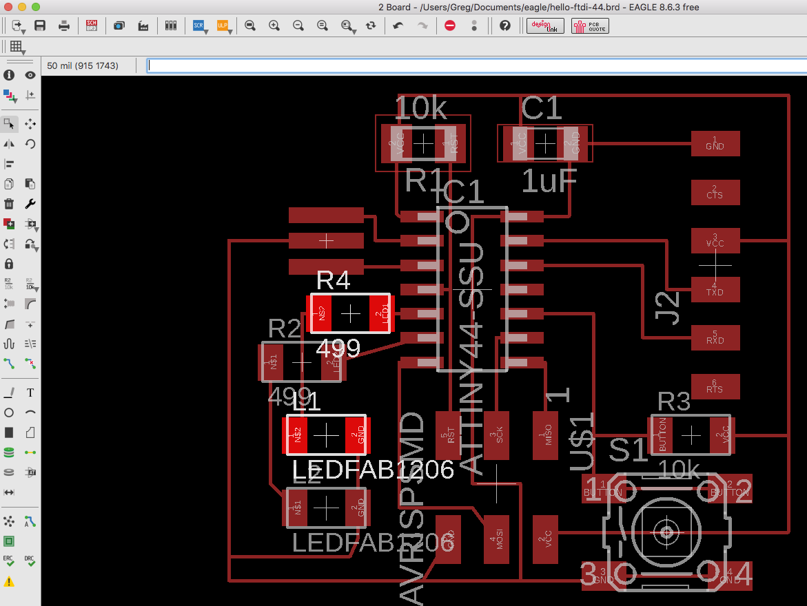
Another snafu here: with the schematic as downloaded, it was not possible to run traces underneath the included 2x3 header. This header was from a Sparkfun library. I swapped it out for the 2x3 header in the fab.lbr library (it's called AVRISPSMD if you have trouble finding it). I was pretty proud of solving this one on my own ;¬)
Another hiccup: after I first ran the Design Rules Check (DRC), I had 86 errors (oh no!). 75 width errors and 11 clearance errors. If you look at the previous photo, you can see the traces were quite thin. Checking the "properties" tab of the wires revealed the width as 6 (what unit is this? is it thou?), but the DRC requires a width of 0.010". I changed the width of all wires to 10 (a quick google search showed me how to change them all at once using the command line) and those 75 width errors cleared up. But now it generated even more clearance errors!
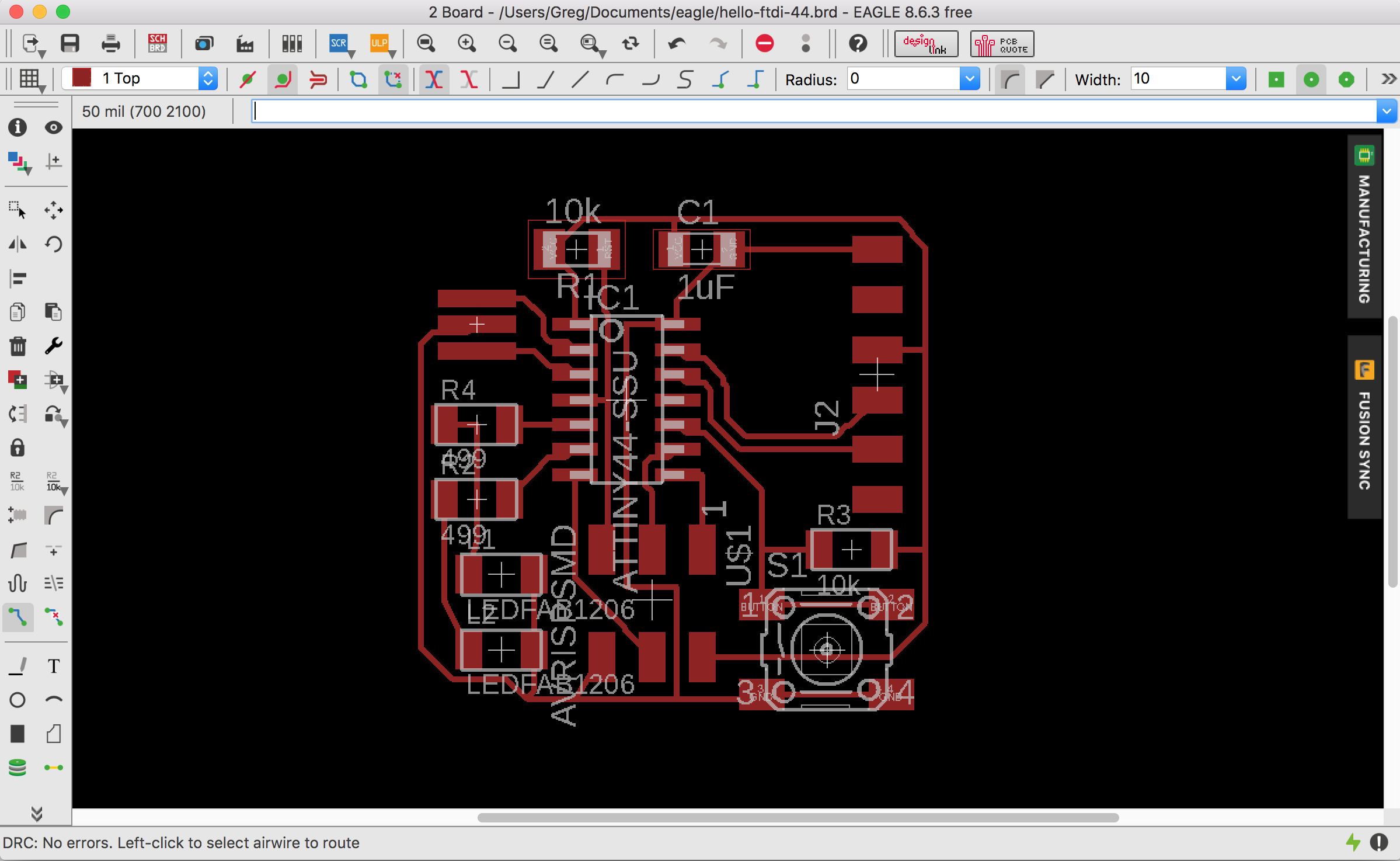
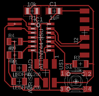
I realized that with my wider traces, it would be quicker and easier to use the Ripup tool to tear come traces out and redo them. (Moving the traces around was more tedious because the snap-to-grid feature made it harder to move them precisely.) After ripping up and re-routing the traces, and adjusting a few component positions, my board passed the DRC with flying colors:
Milling the Board
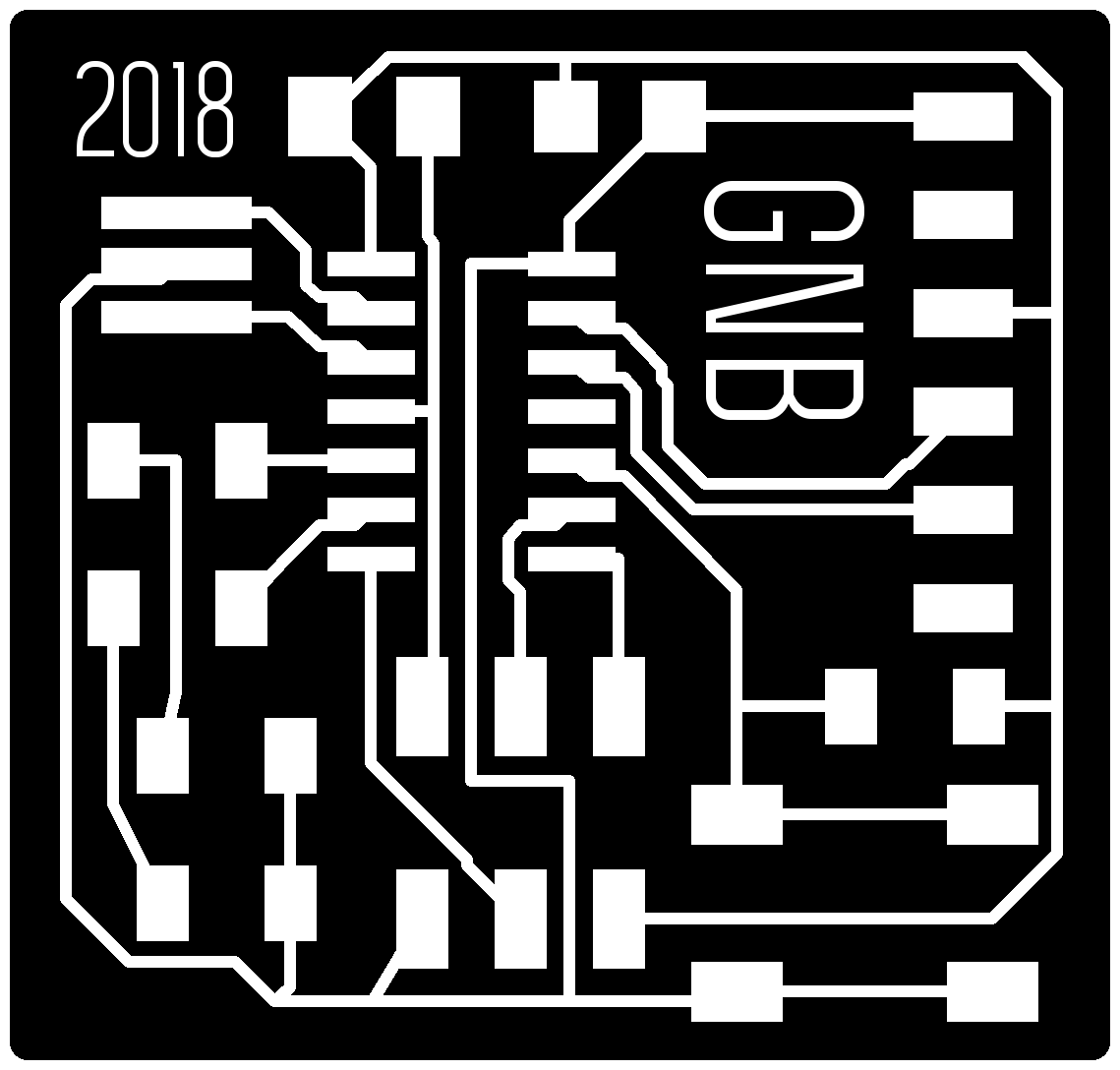
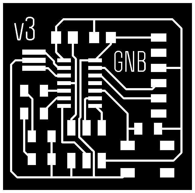
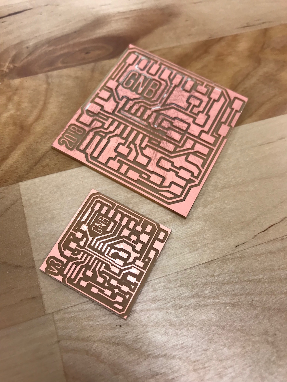
After finishing up the design and passing the DRC, I exported the traces to a monochrome .png file. I added a 10px white border all the way around and rounded the corners. I also added my initials "GNB" and the numeral "2018" to remind me when I made the board.
I then saved a version where the traces are all filled in with black (in other words, deleted). This is the "interior" trace for cutting the board out of its stock material.

This is about where just about everything that could go wrong, did go wrong, and I spent about 9 hours in SNAFU-land.
SNAFU Land
The first several hours of snafu was because the IT department at Dassault had taken away our Mods computer because Windows was not booting (but Ubuntu works just fine, we protested!). After a couple hours trying to get a different computer to talk to the SRM-20, we gave up and asked IT to give us back the computer so we could just run Mods. Then I finally got the mill up and working with Mods, prepped and sent my file, and it milled beautifully:
The only problem, was that the scale was completely wrong.
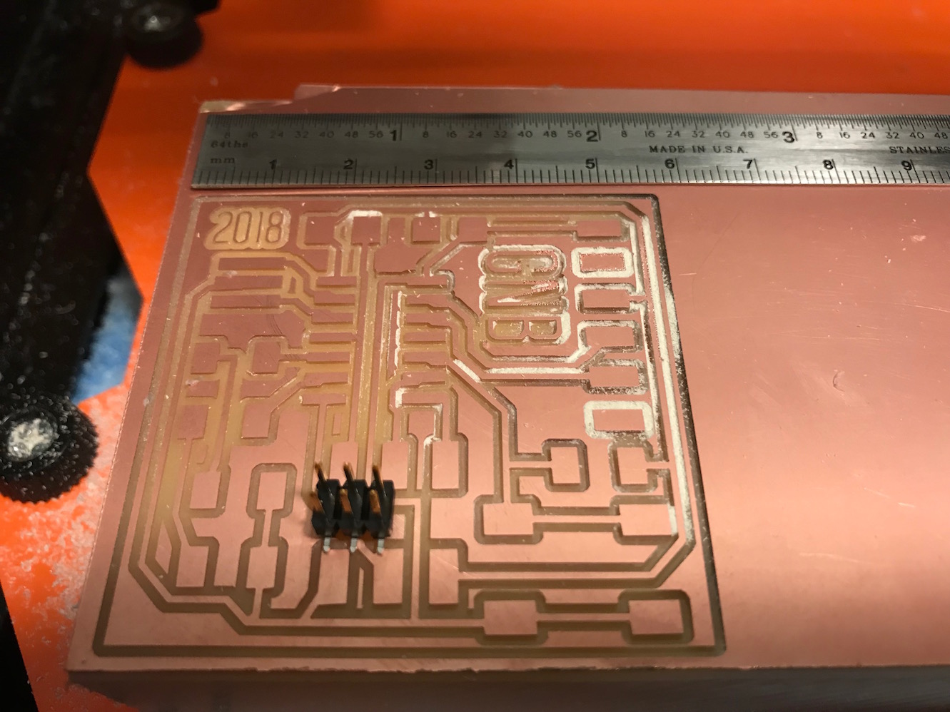
I milled out the interior anyway, but there was no way to make this board work.
Luciano and I spent a fair amount of time troubleshooting this. We could not, for the life of us, get Eagle to export a .png file that was scaled correctly (it kept putting out files that were about 4x too big). As it turns out this is an error in Eagle 8.6.3 for Mac OS that has a scaling export problem. Thank goodness Jean Michel told us this or we could have easily spent another 2 hours trying to troubleshoot. So we installed Eagle for Ubuntu on the mods machine and went from there. That's when I hit my next Snafu.
In spite of passing the Design Rules Check (DRC) with no problems, there was in fact an error in the toolpath that I exported to the monoFab. A trace that runs under the IC was too close to the IC pads, and so the millbit couldn't fit between them and the resulting circuit had a big group of shorts.
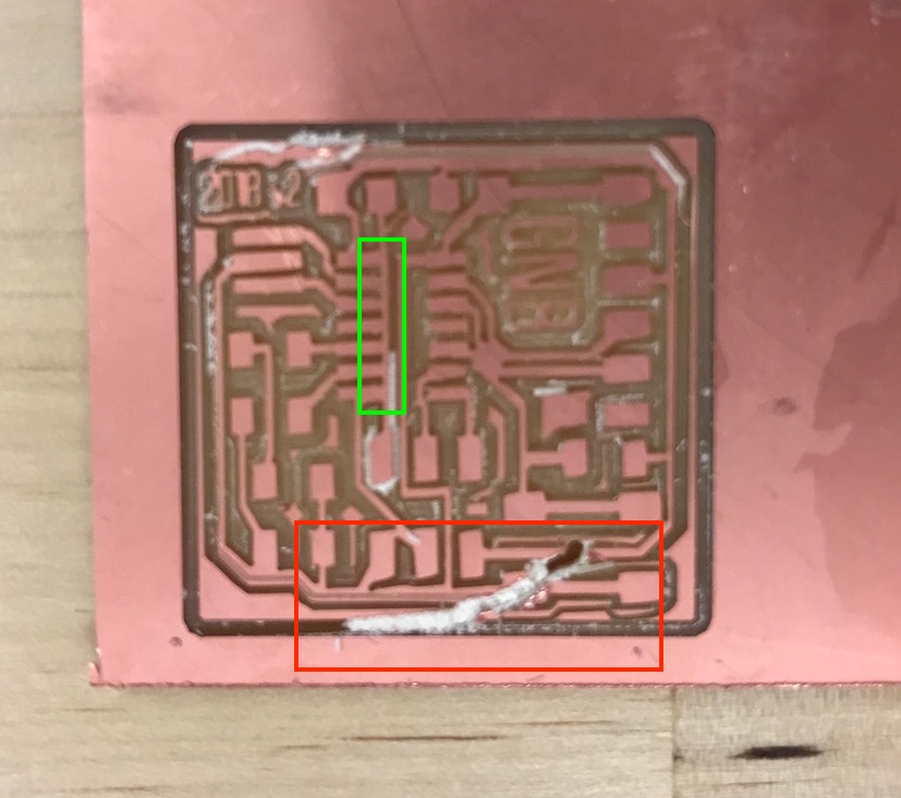
After realizing this toolpath problem, I tried to mill out the board and in that process the double-sided tape gave way and the workpiece detached from the sacrificial material, destroying the piece, and ruining my register. Ugh. It was at this point that I felt it might be one of those days.
Anyway, I went back into Eagle, and rerouted the problematic trace to give it a little more space around the IC pads. I exported new .pngs of the traces and interior.

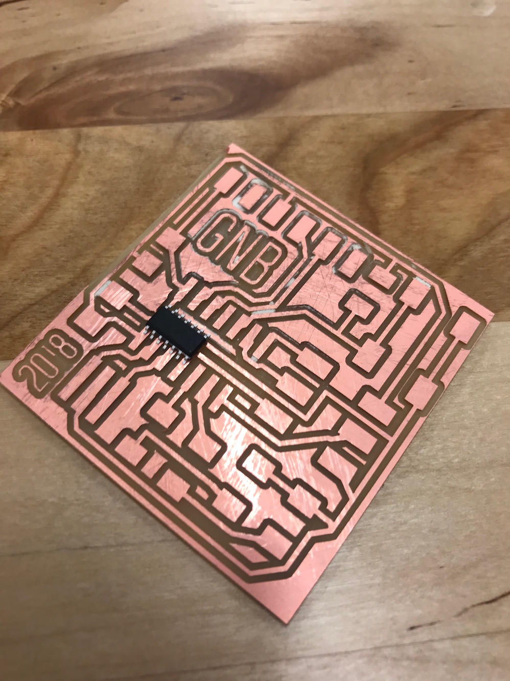
This time (after a couple more hours wrestling with a finicky SRM-20 > mods connection) I finally got a good mill!
Huzzah! This felt like a great success after many obstacles and snares. I felt good about the product and went home to get some rest.
Stuffing the Board
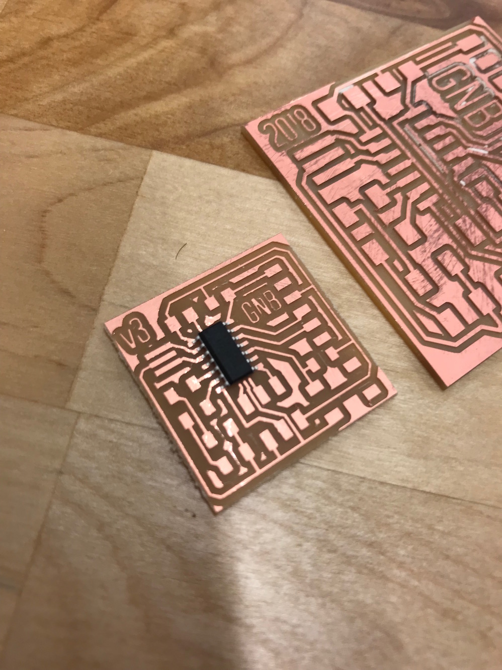
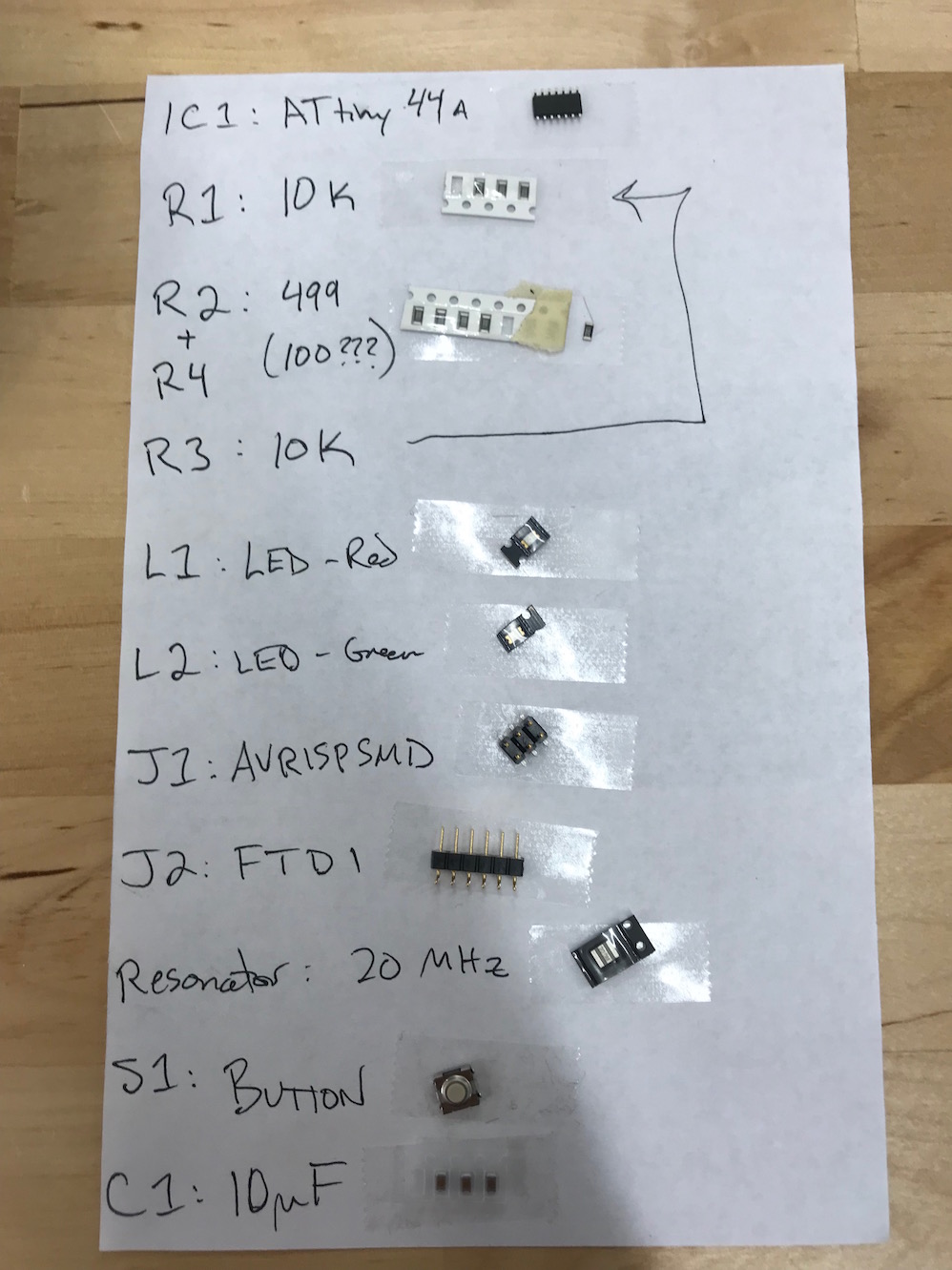
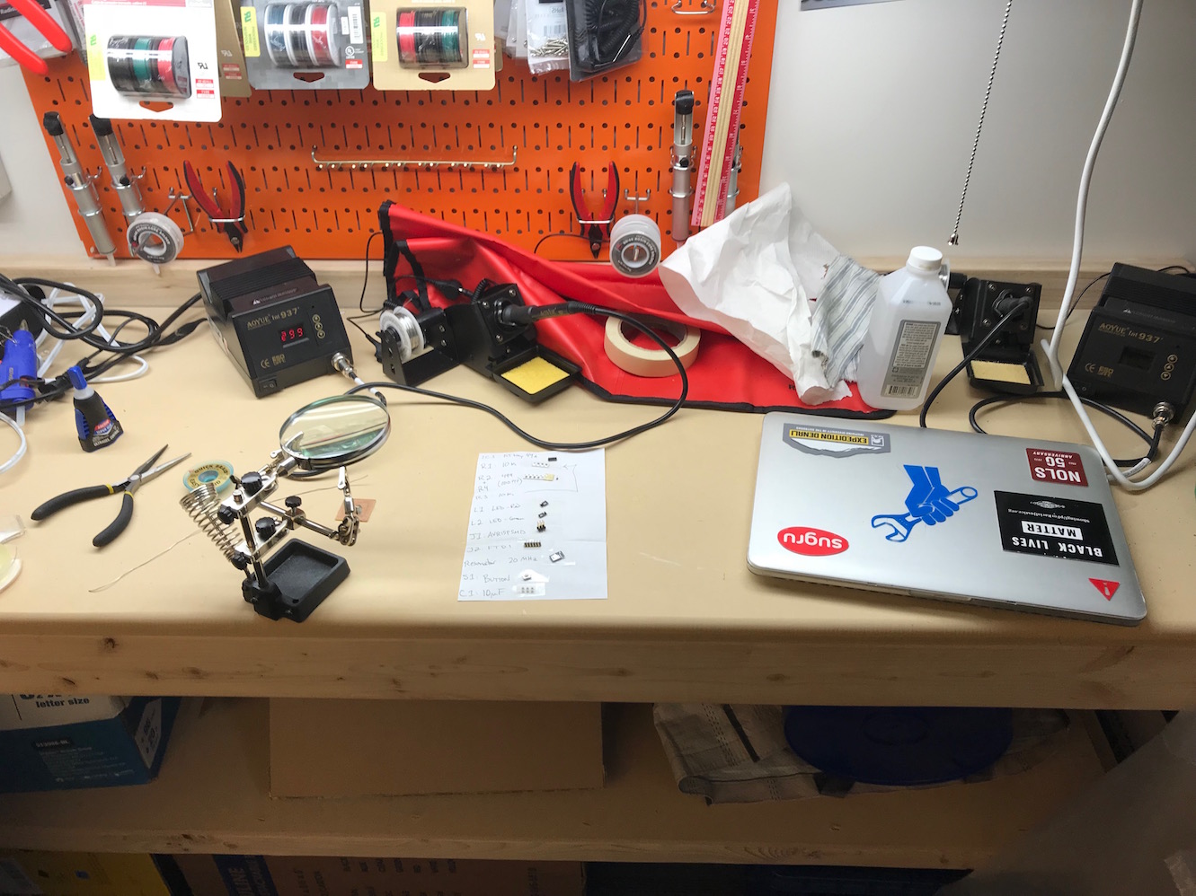
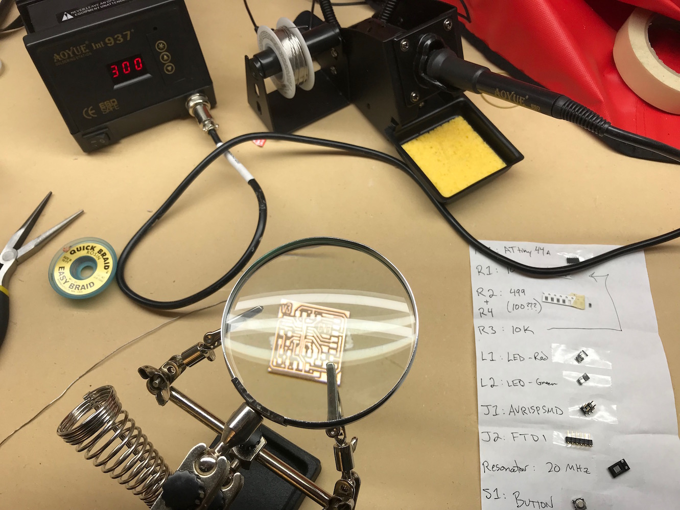
After a good night's sleep, I came into my Fab Lab at Lena Park to stuff the board. I had previously assembled all my components.
I went to work soldering the components to the appropriate locations on the board.
I had one problem when soldering: I found the resonator a little tricky, due to it's 3 contacts and pads. I didn't like the positioning of it, and when I tried to pull de-solder it and remove it, I didn't get all the solder re-flowed and ripped up the ground trace accidentally. After a little mild cursing, I came up with a solution, which was to strip a small piece of 22 AWG wire and solder it in the circuit in place of the ripped out trace.
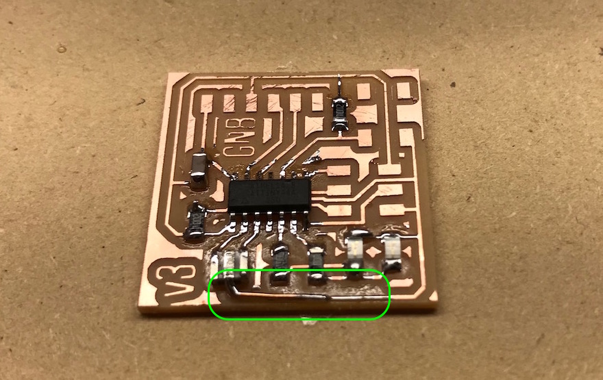
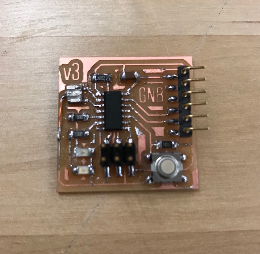
I checked this connection thoroughly with the continuity tester on my multi-meter before continuing. (I wanted to make sure I didn't have to mill a new board before I continued building this one!) It seems to make a good connection, so I stuffed the rest of the board.
Programming the Board
Well, I didn't want to come all this way, through trial and tribulation, farce and frustration, without checking to see if my board worked! So I did a little googling and a little looking ahead to our Embedded Programming week, and figured out how to program my board using the Arduino IDE. I found this tutorial particularly helpful, and basically followed it to burn my bootloader and get started programming my board. FYI, I was not able to get my board to work with the ArduinoISP, but I was able to use my FabISP (from a couple weeks ago) to talk to it. Use the Tools > Programmer > USBTinyISP option to use your FabISP with the ArduinoISP.
I got the Arduino example blink sketch working first (changing the pin number to match the pin number I had attached an LED). Then I played around with the example Button read sketch. Once I had that working, I wrote up a little sketch with a set of pre-programmed blink sequences that could be cycled through using the push button.
// constants won't change. They're used here to set pin numbers:
const int buttonPin = 3;    // the number of the pushbutton pin
const int redPin =  8;      // the number of the red LED pin
const int greenPin = 7;     // the number of the green LED pin

// variables will change:
int buttonState = 0;        // variable for reading the pushbutton status
int blinkNum = 0;           // variable to store the current blink pattern

// the setup function runs once when you power the board
void setup() {
  // initialize digital pins 7 & 8 as an output.
  pinMode(redPin, OUTPUT);
  pinMode(greenPin, OUTPUT);
  //initialize digital pin 3 as input.
  pinMode(buttonPin, INPUT);
}

//turns both LEDs off
void bothOff(){
  digitalWrite(greenPin, LOW);
  digitalWrite(redPin, LOW);
}

//turns both LEDs on
void bothOn(){
  digitalWrite(greenPin, HIGH);
  digitalWrite(redPin, HIGH);
}

//blinks both together
void blinkTogether(){
  bothOn();
  delay(500);
  bothOff();
  delay(500);
}

//blink alternating slow function
void alternateSlow(){
  digitalWrite(redPin, LOW);
  digitalWrite(greenPin, HIGH);
  delay(1000);
  digitalWrite(greenPin, LOW);
  digitalWrite(redPin, HIGH);
  delay(1000);
}

//blink alternating fast function
void alternateFast(){
  digitalWrite(redPin, LOW);
  digitalWrite(greenPin, HIGH);
  delay(100);
  digitalWrite(greenPin, LOW);
  digitalWrite(redPin, HIGH);
  delay(100);
}

//SOS blinking function
void sos(){
  bothOff();
  for (int x = 0; x < 3; x++){    //do 3 times
    digitalWrite(greenPin, HIGH);   // turn the LED on (HIGH is the voltage level)
    delay(100);                       // wait for a 100ms
    digitalWrite(greenPin, LOW);    // turn the LED off by making the voltage LOW
    delay(100);                       // wait for a 100ms
  }
  delay(500);
  for (int x = 0; x < 3; x++){    //do 3 times
    digitalWrite(redPin, HIGH);   // turn the LED on (HIGH is the voltage level)
    delay(500);                       // wait for 500ms
    digitalWrite(redPin, LOW);    // turn the LED off by making the voltage LOW
    delay(100);                       // wait for 100ms
  }
  delay(500);
  for (int x = 0; x < 3; x++){    //do 3 times
    digitalWrite(greenPin, HIGH);   // turn the LED on (HIGH is the voltage level)
    delay(100);                       // wait for 100ms
    digitalWrite(greenPin, LOW);    // turn the LED off by making the voltage LOW
    delay(100);                       // wait for 100ms
  }
  delay(1000);               //wait 1 second
}

void blinkN(int n){
  bothOff();
  for (int i = 0; i < blinkNum; i++){
    digitalWrite(greenPin, HIGH);
    delay(200);
    digitalWrite(greenPin, LOW);
    delay(200);
  }
  digitalWrite(redPin, HIGH);
  delay(1000);
  digitalWrite(redPin, LOW);
}

void blinkPattern(int n){
  switch (n){
    case 0:
      bothOff();
      break;
    case 1:
      bothOn();
      break;
    case 2:
      blinkTogether();
      break;
    case 3:
      alternateSlow();
      break;
    case 4:
      alternateFast();
      break;
    case 5:
      sos();
      break;
    case 6:
      blinkN(blinkNum);
      break;
    default:
      bothOff();
      blinkNum = 0;
  }
}

// the loop function runs over and over again forever
void loop() {
  //read the state of the pushbutton value
  buttonState = digitalRead(buttonPin);


  //check if the pushbutton is pressed, if it is, increment the blinkNum by 1
  if (buttonState == LOW){
    delay(1000);
    if (blinkNum < 6){
      blinkNum++;
    }
    else
      blinkNum = 0;  //if blinkNum >= 6 then reset blinkNum to 0
  }


  blinkPattern(blinkNum);


  /*
  //testing regime for counting blinkNum
  if (buttonState == LOW){
    blinkNum++;
    delay(500);
  }

  blinkN(blinkNum);
  */

}
After a little bit of trouble shooting, I got this working with my two LEDs (red and green). I'm quite happy with the result, and in fact have found it somewhat mesmerizing. Here's a video.
Design Files
Hello FTDI 44 GNB Eagle schematic file (.SCH file)
Hello FTDI 44 GNB Eagle board file (.BRD file)
Hello FTDI 44 GNB - Monochrome GIMP file with layers (.xcf file)