Week 10: Input Devices
Measure something: add a sensor to a microcontroller board that you have designed and read it.
Learning outcomes:
- Demonstrate workflows used in circuit board design and fabrication
- Implement and interpret programming protocols
Have you:
- Described your design and fabrication process using words/images/screenshots.
- Explained the programming process/es you used and how the microcontroller datasheet helped you.
- Explained problems and how you fixed them
- Included original design files and code
My Process
Background
Basically, my background here consists of what I did in previous weeks. I am interested in using a microphone and an accelerometer in my final project, so I think I'd like to make a board that includes each of those things. I'm also interested in the ultrasonic sensor, so I might try to do that one for extra credit.
Getting Started
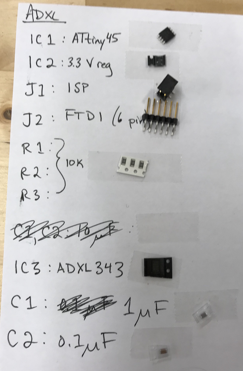
I familiarized myself with the accelerometer and microphone boards that Neil presented in class. I decided to start with the accelerometer board.
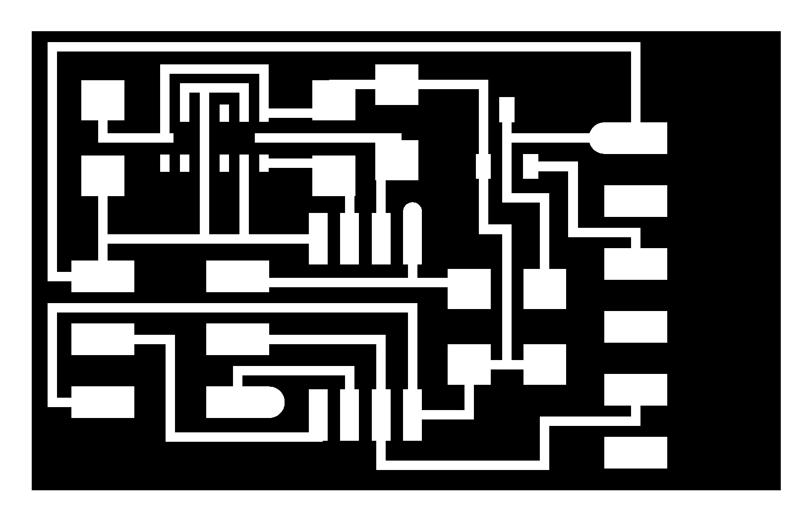
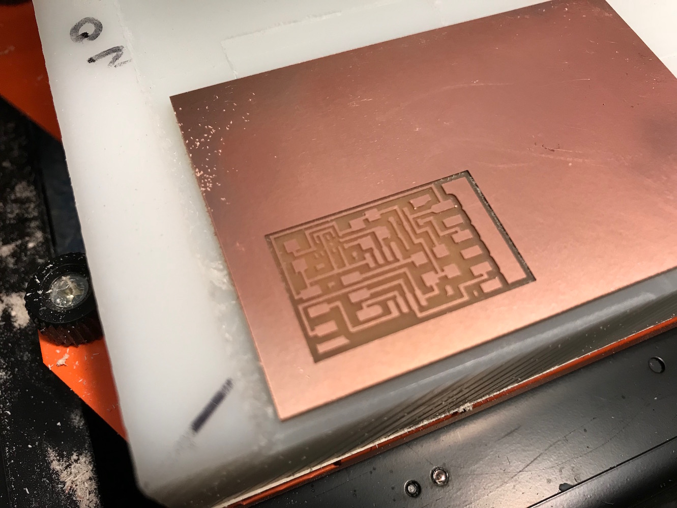
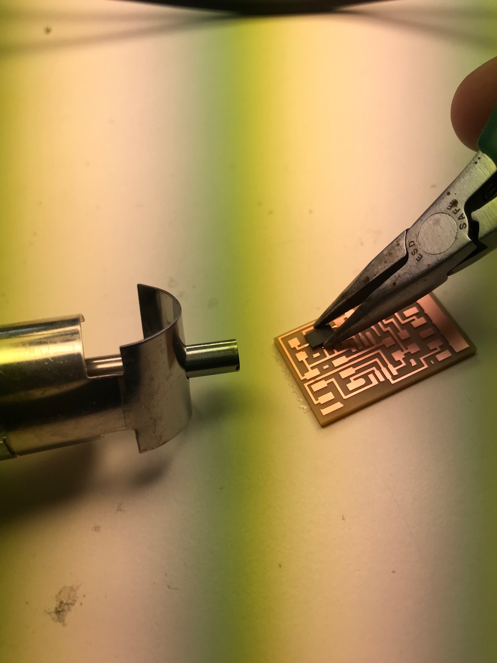
I got the traces and interior files ready to mill:

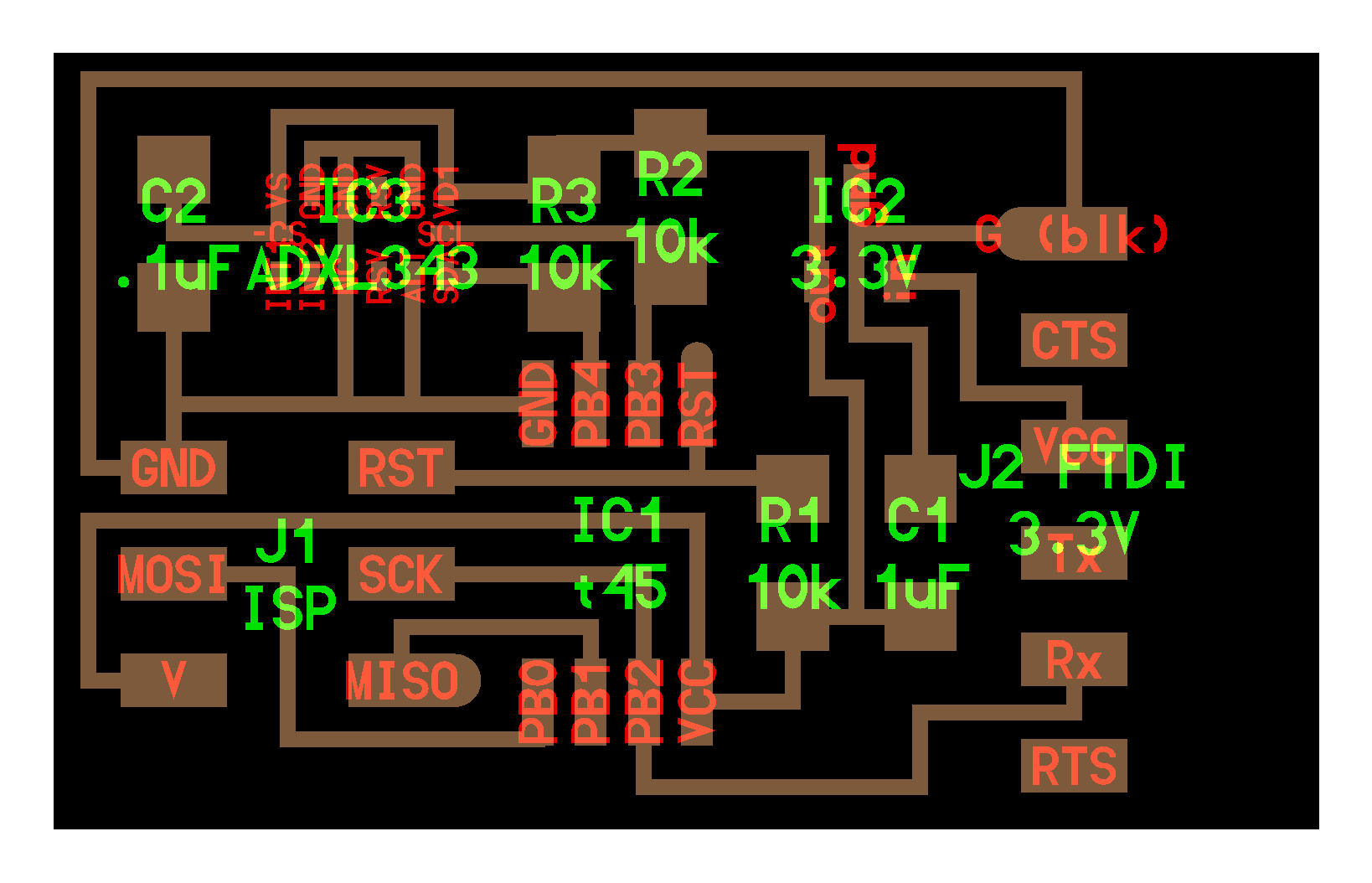
One question I had: Why is the FTDI listed as 3.3v if there is also a 3.3v voltage regulator? Wouldn't we want a 5v FTDI so as not to lose voltage across the regulator?
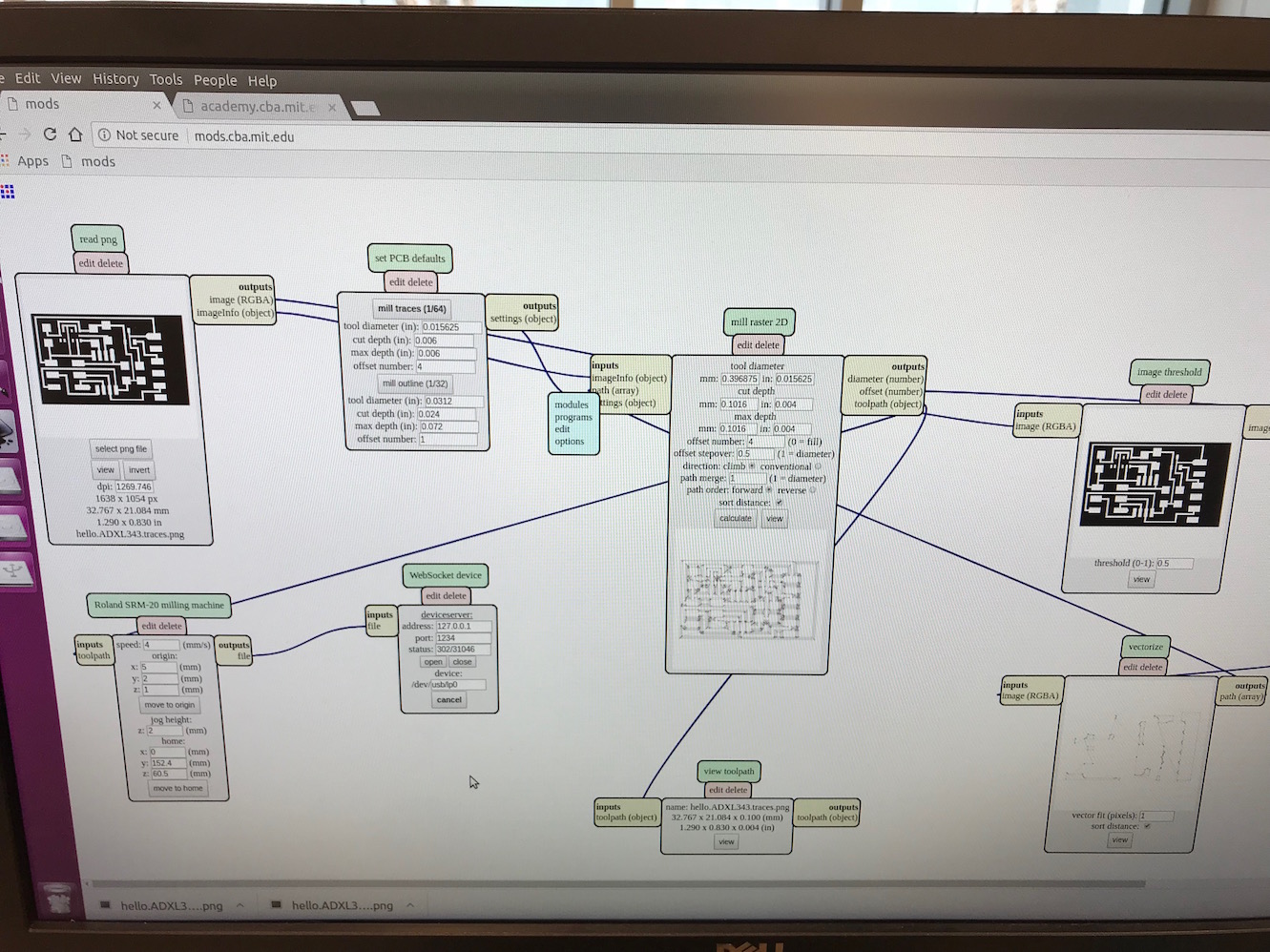
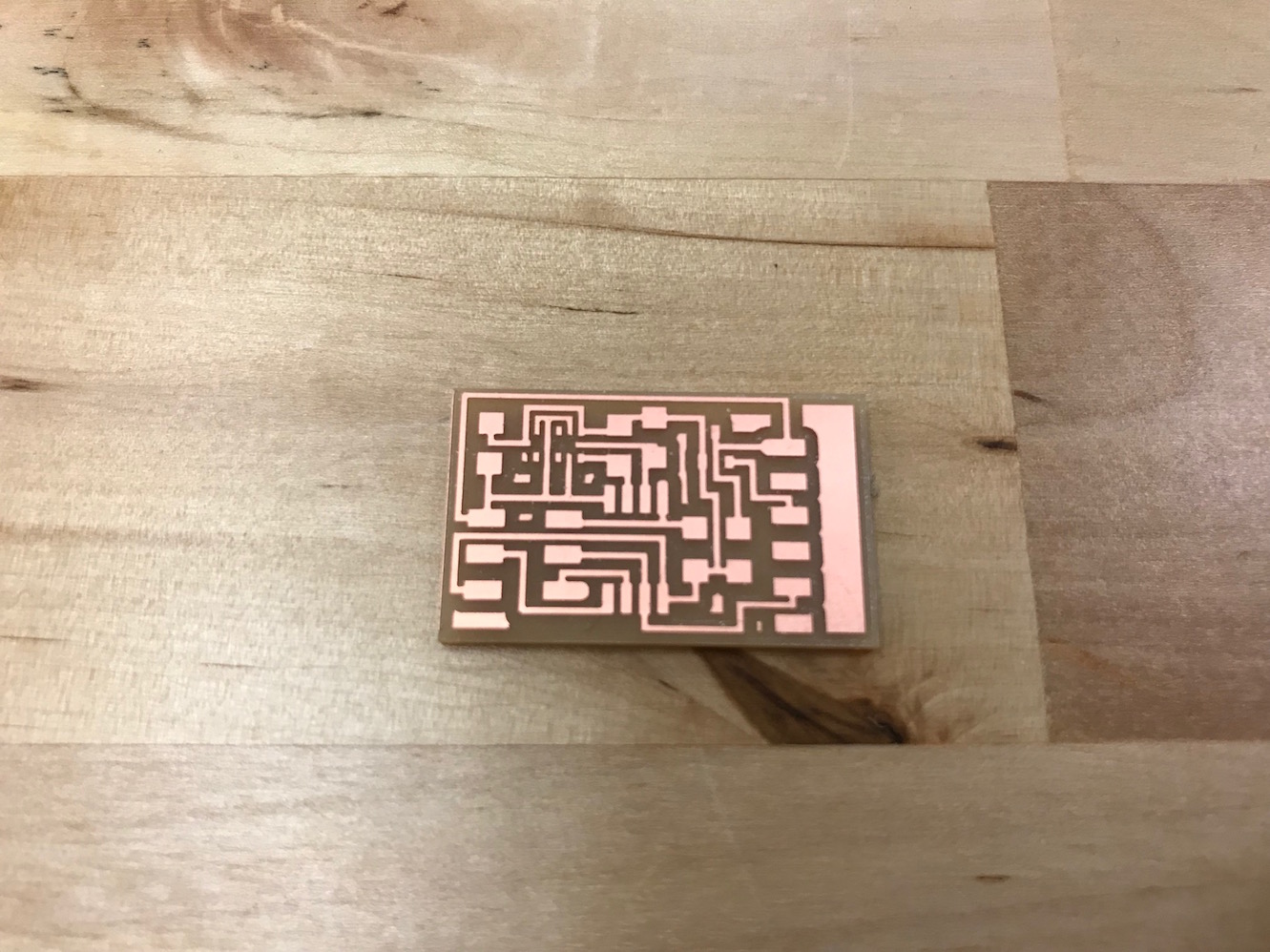
I loaded these up in mods an milled the board.
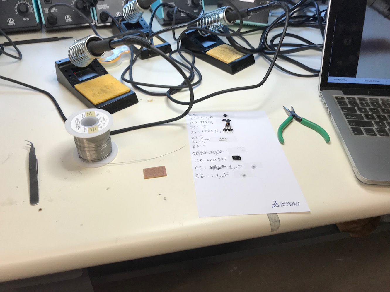
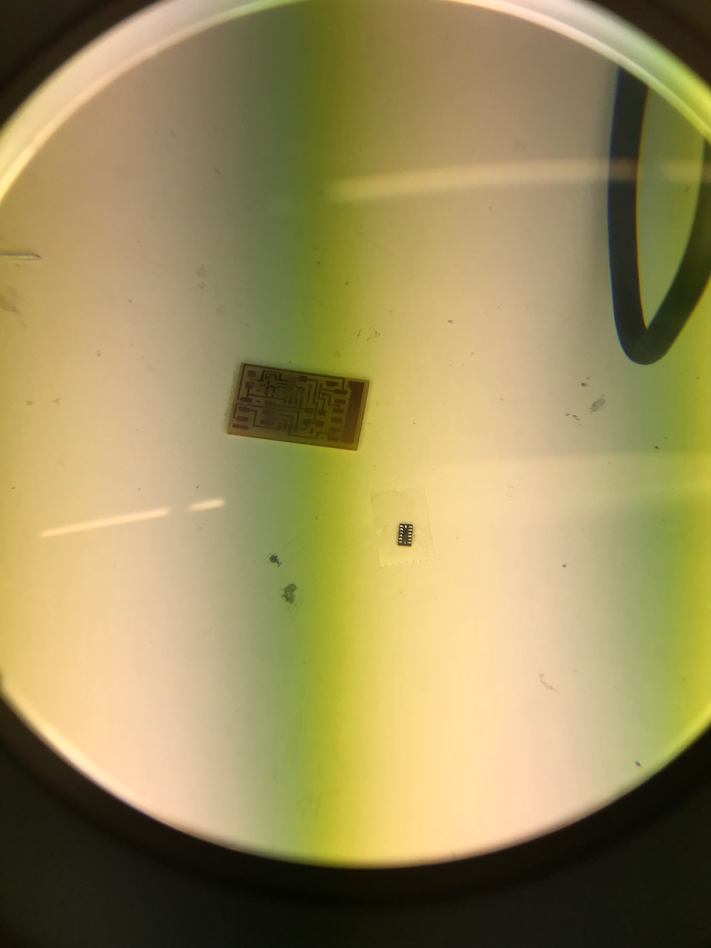
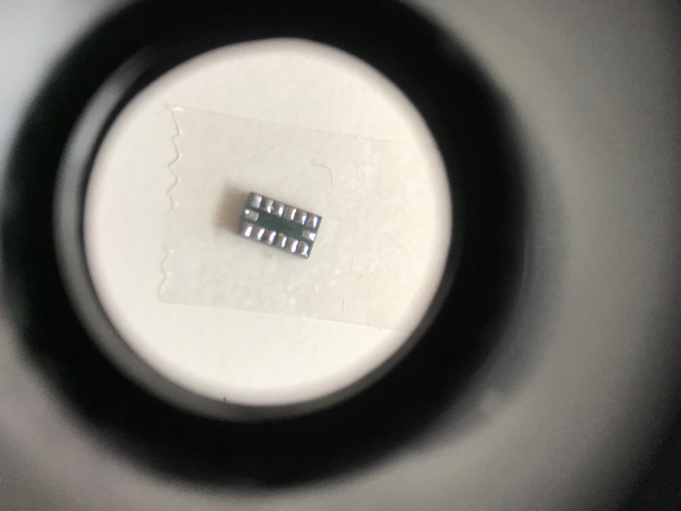
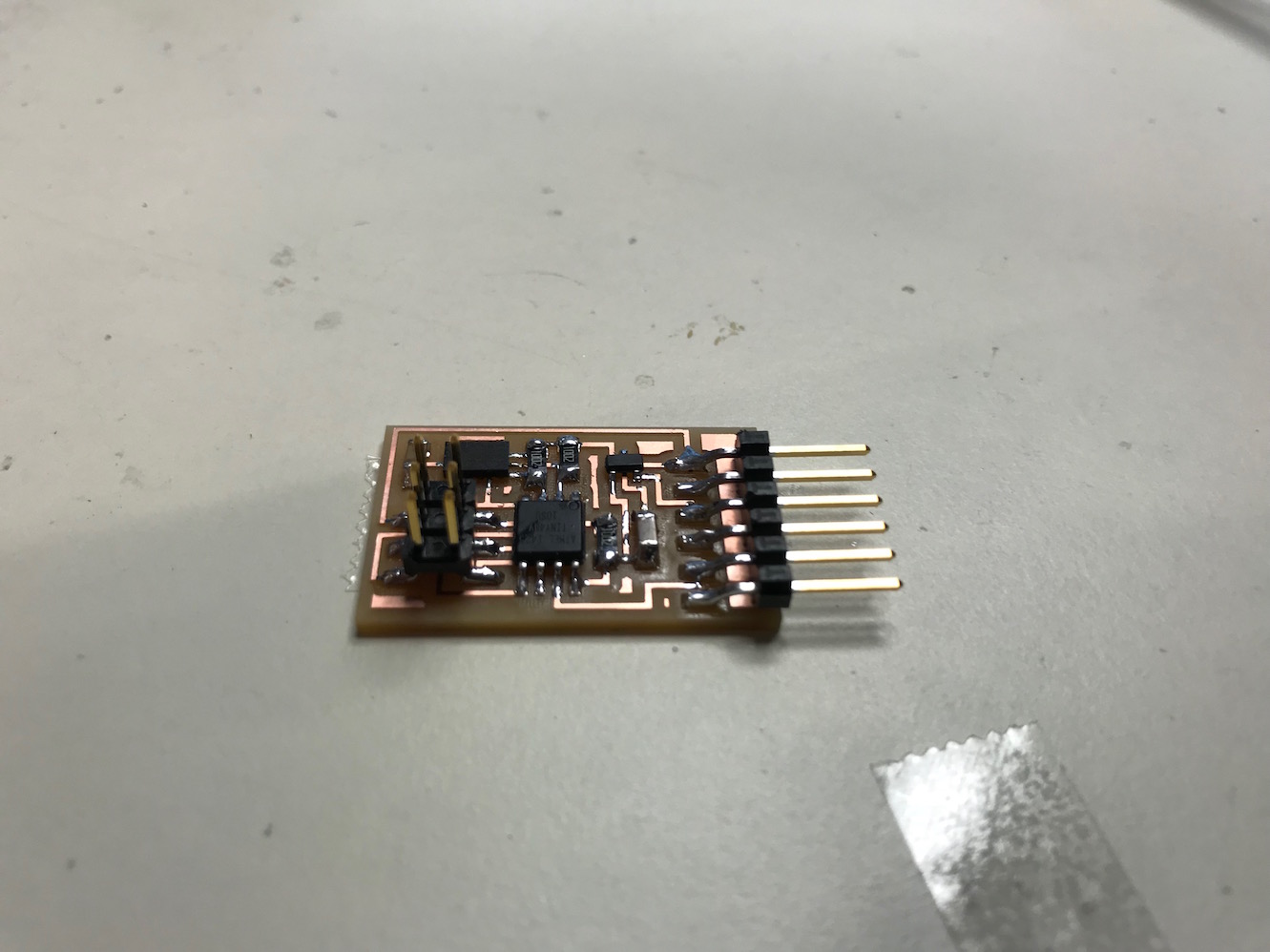
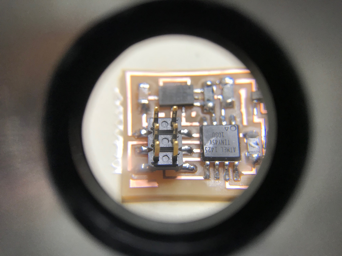
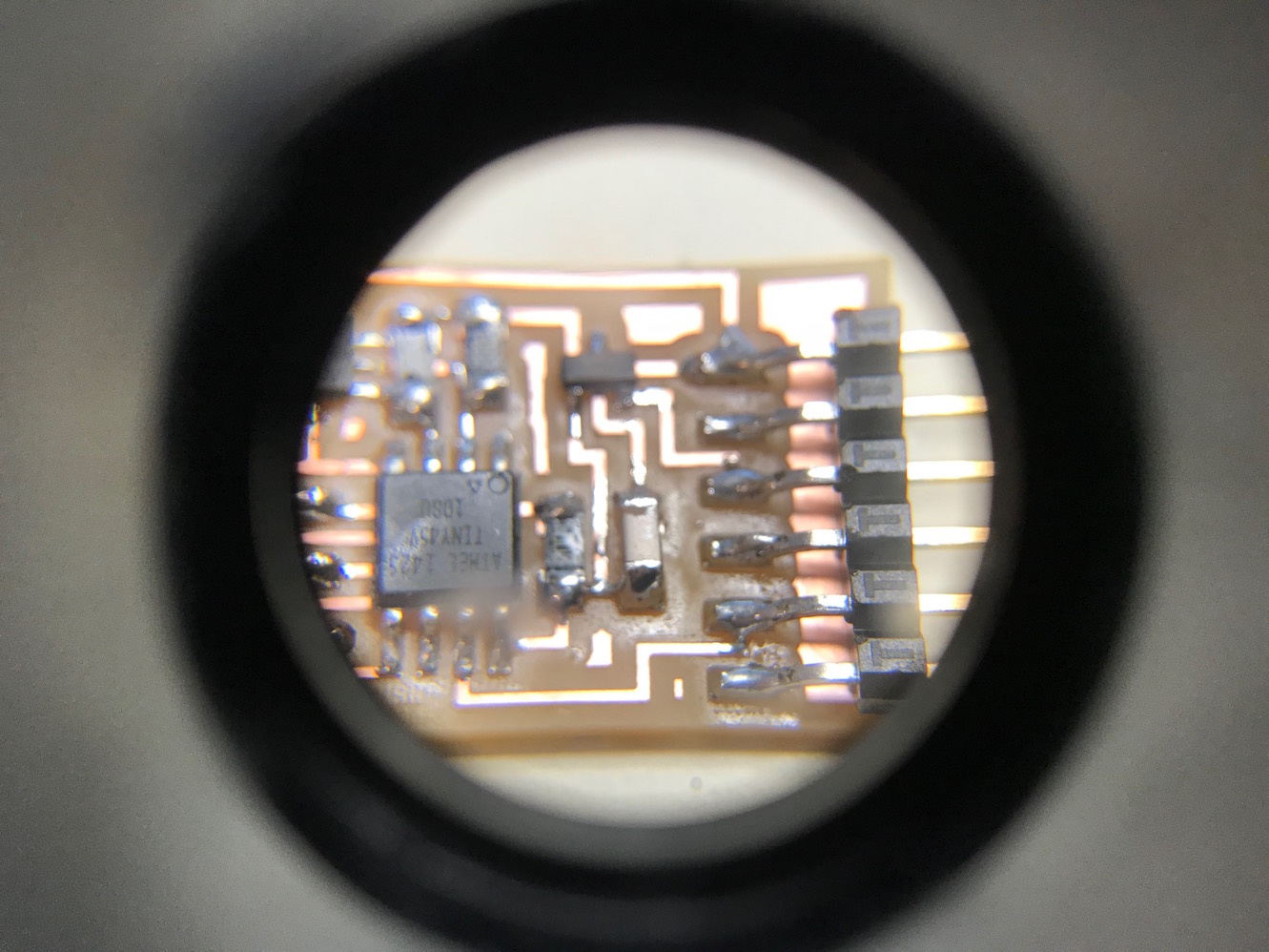
For soldering the accelerometer, I followed Neil's hints and tinned the traces/pads on the board as well as the pads on the bottom of the package.
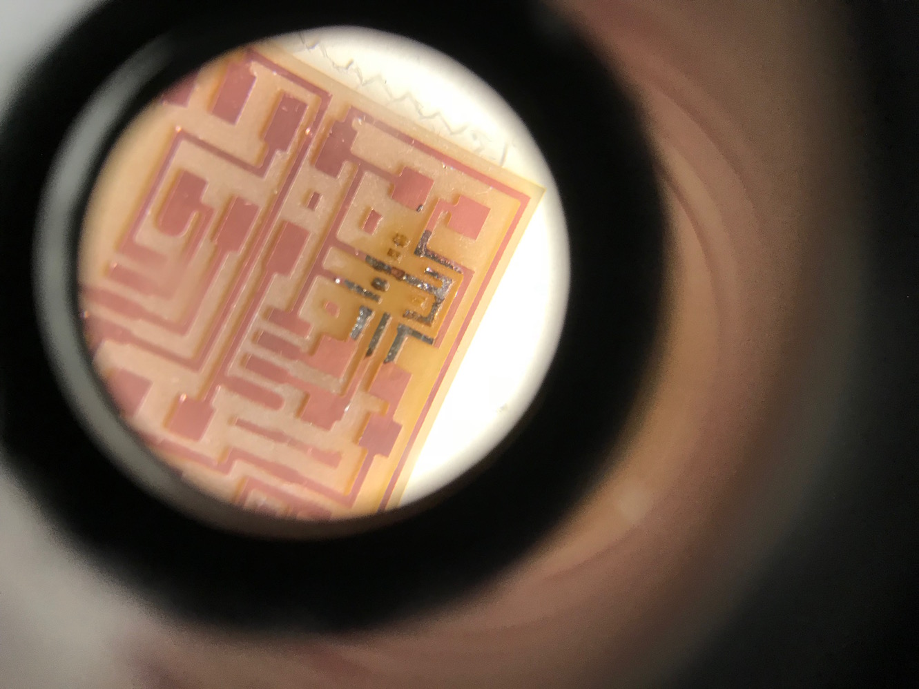
I then used the fine-tipped heat gun to reflow the solder to make the connections to the board.
Programming the Board
I started by connecting the board to my ISP and burning a bootloader via the Arduino IDE, essentially the same as I did in Week 08: Embedded Programming. Except this time I selected Tools > Board: "ATtiny25/45/85", Tools > Processor: "ATtiny45" and Tools > Clock: "Internal 8 MHz".
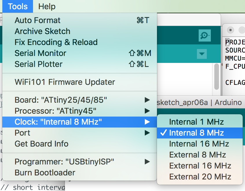
Once I had those setting right, I selected Tools > Burn Bootloader and waited for the "Done Burning Bootloader" message from the IDE.
Now that the bootloader was burned, I loaded Neil's C-code program for the Hello ADXL board. I downloaded the Makefile and renamed it "Makefile". I navigated to the folder containing the code in a terminal, plugged in my ISP and ran the command make program-usbtiny and got the following output:
Greg$ make program-usbtiny
avr-objcopy -O ihex hello.ADXL343.out hello.ADXL343.c.hex;\
	avr-size --mcu=attiny45 --format=avr hello.ADXL343.out
AVR Memory Usage
----------------
Device: attiny45

Program:    1062 bytes (25.9% Full)
(.text + .data + .bootloader)

Data:          0 bytes (0.0% Full)
(.data + .bss + .noinit)


avrdude -p t45 -P usb -c usbtiny -U flash:w:hello.ADXL343.c.hex

avrdude: AVR device initialized and ready to accept instructions

Reading | ################################################## | 100% 0.00s

avrdude: Device signature = 0x1e9206
avrdude: NOTE: "flash" memory has been specified, an erase cycle will be performed
         To disable this feature, specify the -D option.
avrdude: erasing chip
avrdude: reading input file "hello.ADXL343.c.hex"
avrdude: input file hello.ADXL343.c.hex auto detected as Intel Hex
avrdude: writing flash (1062 bytes):

Writing | ################################################## | 100% 0.97s

avrdude: 1062 bytes of flash written
avrdude: verifying flash memory against hello.ADXL343.c.hex:
avrdude: load data flash data from input file hello.ADXL343.c.hex:
avrdude: input file hello.ADXL343.c.hex auto detected as Intel Hex
avrdude: input file hello.ADXL343.c.hex contains 1062 bytes
avrdude: reading on-chip flash data:

Reading | ################################################## | 100% 1.23s

avrdude: verifying ...
avrdude: 1062 bytes of flash verified

avrdude: safemode: Fuses OK (H:FF, E:DF, L:E2)

avrdude done.  Thank you.
Success! The C-code seems to have loaded correctly. Next up is to get the python script running. I ran the command python hello.ADXL343.py (which is not correct in the first place, see below) and got the following error:
Greg$ python hello.ADXL343.py
Traceback (most recent call last):
  File "hello.ADXL343.py", line 18, in <module>
    import serial
ImportError: No module named serial
A little googling suggested that I needed to install pyserial on my mac - a set of python libraries that allow python to talk to the serial ports on the computer. I installed pyserial a couple different ways, and still got the same error. What I then discovered was that I had to run the python script from inside the folder where pyserial was installed. Ugh!
Once I figured that out, I copied the python script the folder where pyserial had been installed, and ran python hello.ADXL343.py and got:
command line: hello.accel.45.py serial_port
Finally, I figured out the correct command: python hello.ADXL343.py /dev/tty.usbserial (the serial port I got from opening up the Arduino IDE with the FTDI cable plugged in). It connected up and ran the python script.
16_python_running from Greg Buckland on Vimeo.
I finally got the python script running and connected to the board, but the input on the screen didn't seem to match the movement of the accelerometer. Sad Trombone.
After looking at it some more, I realized that the python script is responsive to the movement of the board at first, but it begins to acrue a delay, which gets worse over time. Each time I run the python script, it's quite responsive at first, but then gets less and less responsive as the delay builds. See video:
18_python_delay from Greg Buckland on Vimeo.
Addendum: I realize that this week may not quite satisfy the requirement for "Input Devices" because I did not design my own board, but just used Neil's (at the time, I did not understand the requirement). In Week 11 I used a potentiometer as an input device to control a motor using Pulse-Width Modulation. If this is not sufficient for an input device on a board I designed myself, please let me know ASAP. My final project will also include an input device which I can include here. Thanks!