Week 12: Interface and Application Programming
Write an application that interfaces with an input and/or output device that you made, comparing as many tool options as possible
Learning outcomes:
- Interpret and implement design and programming protocols to create a Graphic User Interface (GUI)
Have you:
- Described your process using words/images/screenshots.
- Explained the GUI that you made and how you did it.
- Outlined problems and how you fixed them
- Included original code
Source: Fab Academy Assessment - Interface and Application Programming
My Process
Background
So last week I got a motor driven with pulse-width-modulation (PWM) controlled with a potentiometer read by my ATtiny44, but I was still having trouble driving my A4953 H-bridge chip through software (i.e. writing a program to drive the motor at different speeds and directions). So to start with this week, I first needed to get the motor working with PWM, and then get an interface working for it.
Getting Started
To begin with, I needed to get the motor working with PWM. I spent some time writing different Arduino code and trying to drive the motor. I was finding that even if I used the analogWrite function, the motors response was always all-or-nothing. I spent some time with the oscilloscope looking at the signals sent to the H-bridge pins (in1 and in2) and also at the power coming out of the H-bridge (out1 and out2). It became clear that if I sent analogWrite a number greater than 128, it drove the motor full speed, while a number less than 128 didn't drive it at all. You can see the on/off response in the motor and on the yellow trace, measuring the voltage out to the motor.
01_on_off_motor from Greg Buckland on Vimeo.
After a little head-scratching (and maybe a little head banging), I finally realized: the ATtiny pins I had connected up to in1 and in2 on the H-bridge were not capable of Pulse Width Modulation! D'oh! I had followed the example of Neil's "helloDCmotor" board, and he did not use PWM in his code and had not connected his H-bridge to PWM-capable pins (he used PA2 and PA3, which do not have PWM). At least it was a clear and solvable problem; I had to reroute the traces to pins that have PWM capability. I chose to use PA6 and PA7, which have PWM.
After rerouting the traces to the new PWM pins in the driver worked great. The video below shows the motor cycling through various speeds, using PWM. The yellow trace on the oscilloscope shows the PWM traces with the varying loads corresponding to motor speed.
06_pwm_motor_control from Greg Buckland on Vimeo.
The arduino code that drove this motor at varying speeds was quite simple - it took no inputs, and just varied the PWM output in succession from off, slow, medium, and fast. It was something like this:
//this one changes the speed of the motor stepwise going off, slow, medium, fast, full
//

#define in1 6
#define in2 7
#define fwdDelay 2000   //delay between changes
//#define revDelay 2000   //unused - leave commented
//#define delDelay 250

void setup() {
  // put your setup code here, to run once:
  //pinMode(in1, OUTPUT);   //seems there's no need for these two lines so I left them commented out
  //pinMode(in2, OUTPUT);

}

void loop() {
  // put your main code here, to run repeatedly:

  analogWrite(in1, 0);
  analogWrite(in2, 0);
  delay(fwdDelay);

  analogWrite(in1, 50);
  analogWrite(in2, 0);
  delay(fwdDelay);

  analogWrite(in1, 100);
  analogWrite(in2, 0);
  delay(fwdDelay);

  analogWrite(in1, 200);
  analogWrite(in2, 0);
  delay(fwdDelay);

  analogWrite(in1, 255);
  analogWrite(in2, 0);
  delay(fwdDelay);


}
Redesigning my Board
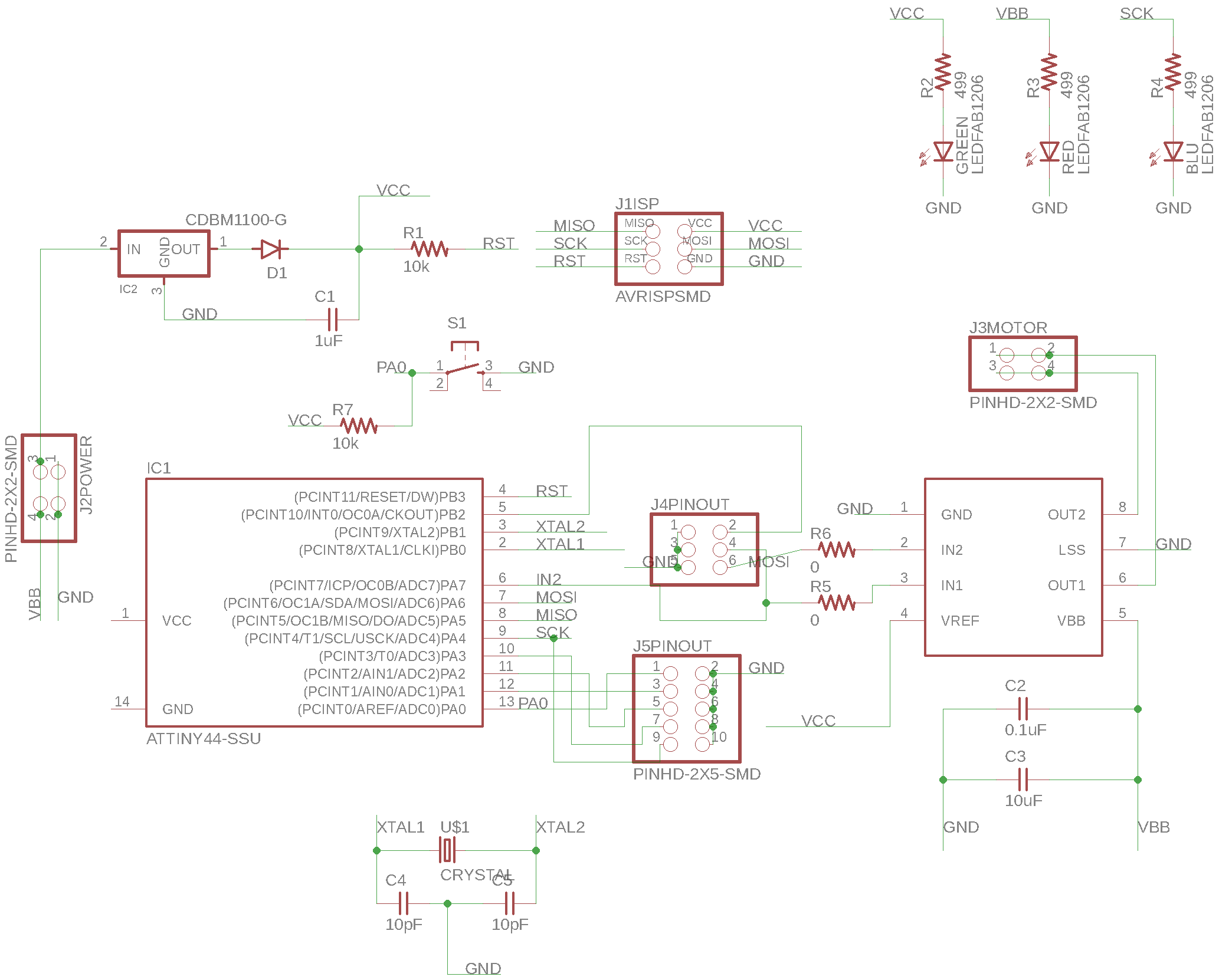
Equipped with my learnings, I decided to redesign my board, using PA6 and PA7 to drive the H-bridge via PWM. I also wanted to add a few features:
- A green LED to show when 5v power is supplied
- A red LED to show when 12v power is supplied
- A blue LED that can be used to blink and signal during device operation
- A diode after the voltage regulator to prevent current from "backflowing" into the regulator and overheating the component (for example, when I plug in my ISP for programming the board)
- A button to allow input directly on the board
- Breakout headers to be able to access more pins on the chip for other uses if need be (e.g. serial communication)
I added all the features I wanted to the schematic:
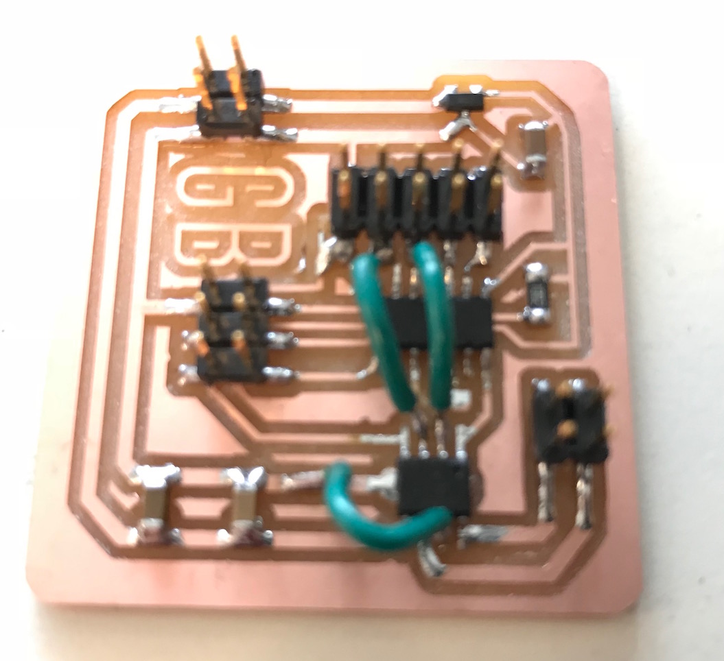
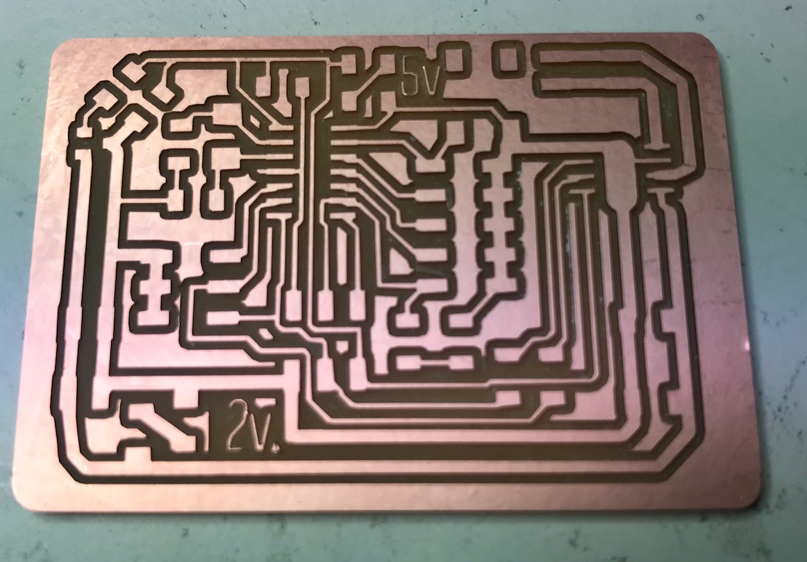
After redesign, it took quite a bit of trace rerouting, but I find I really enjoy that task. I find it somewhat meditative actually. I was pretty happy with my board layout:
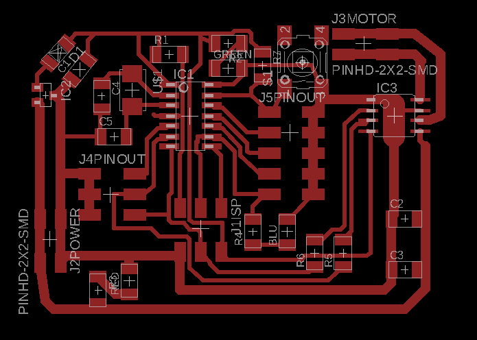
I got the trace and interior files ready for milling via mods.

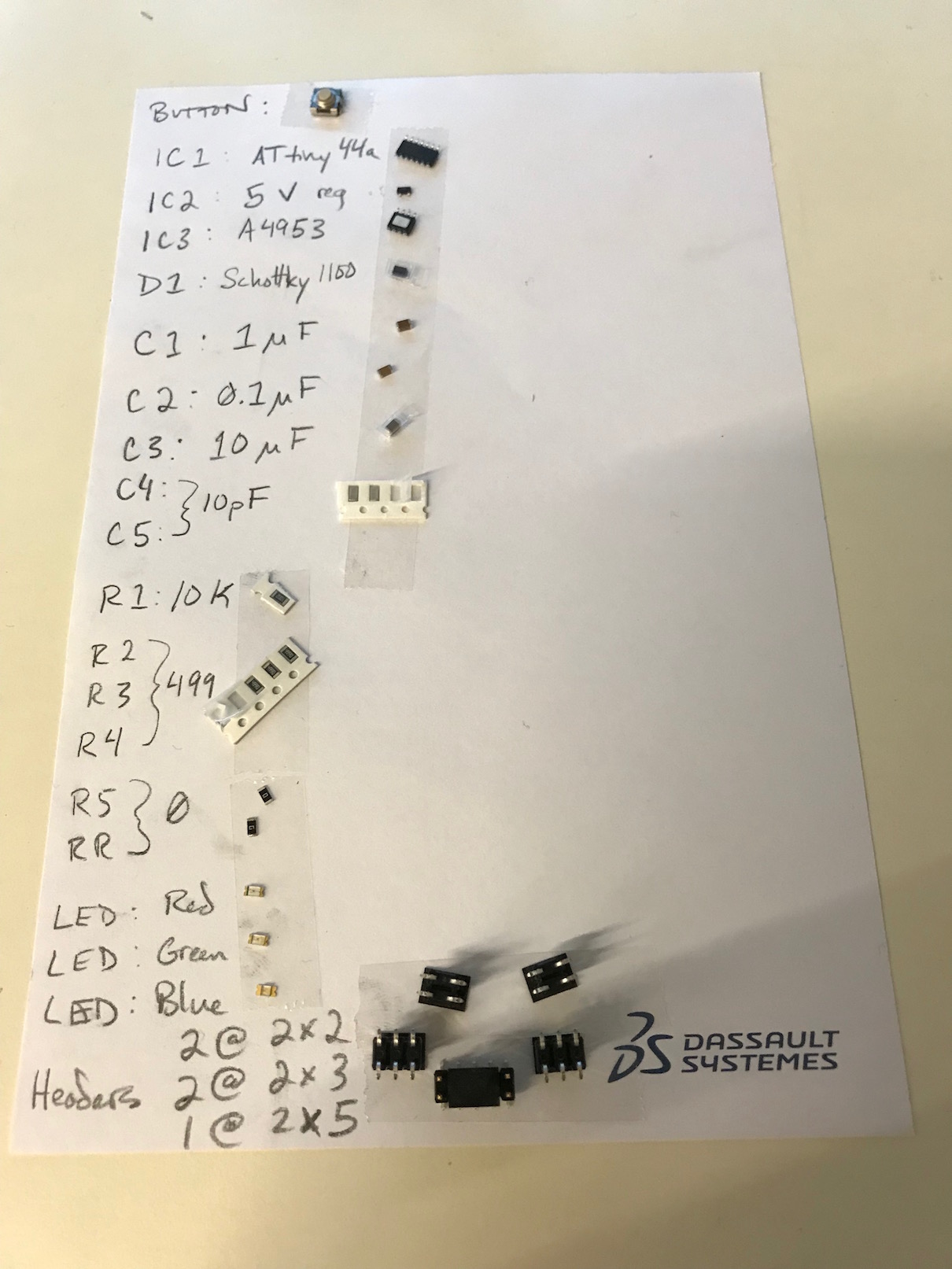
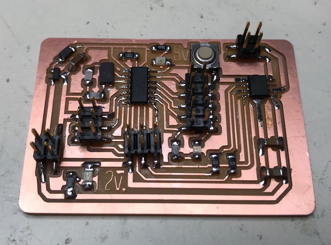
I went through my normal milling and stuffing process, assembling components while the milling was going on:
I wrote a simple program to blink the blue LED, and it worked great!
int bluePin = 4;

void setup() {
  // put your setup code here, to run once:
  pinMode(bluePin, OUTPUT);
}

void loop() {
  // put your main code here, to run repeatedly:
  digitalWrite(bluePin, HIGH);
  delay(500);
  digitalWrite(bluePin, LOW);
  delay(500);
}
Next I wanted to make a sketch that toggled the LED when the button was pressed. I wrote the following:
#define bluePin 4
#define buttonPin 0

int buttonState = 0;

bool ledOn = false;

void setup() {
  // put your setup code here, to run once:
  pinMode(bluePin, OUTPUT);
  pinMode(buttonPin, INPUT);
}

void loop() {
  // put your main code here, to run repeatedly:
  buttonState = digitalRead(buttonPin);

  if (buttonState == LOW){  //if button is pushed
    if (ledOn){       //check if led is on
      digitalWrite(bluePin, LOW); //if on, turn it off
      ledOn = false;
    } else if (!ledOn){   //if not on
      digitalWrite(bluePin, HIGH);  //turn it on
      ledOn = true;
    }
  }
  delay(100); //delay 100ms (gives user time to release button)
}
Well, it didn't behave quite right. The button seemed to work very sporadically / inconsistently, and the light seemed to come on and off at random. And then I began to discern a pattern. When my hand was near the back of the board, the LED lit up:
12_step_response from Greg Buckland on Vimeo.
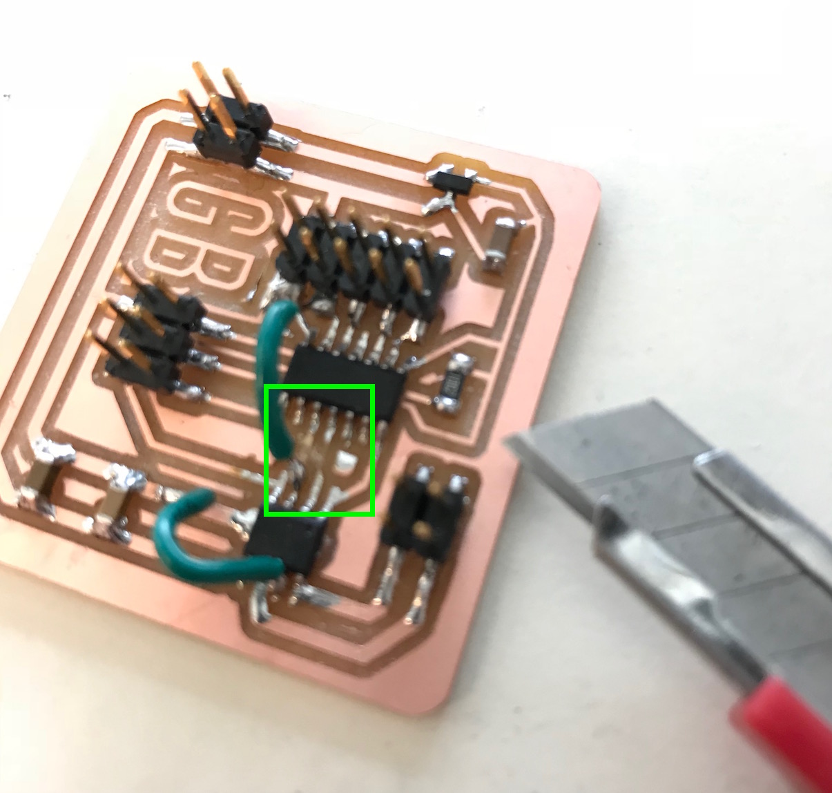
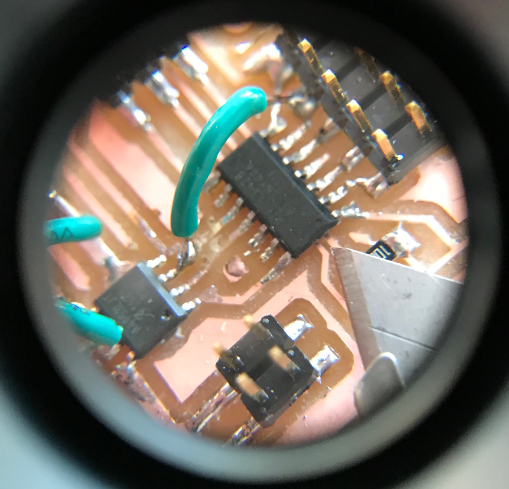
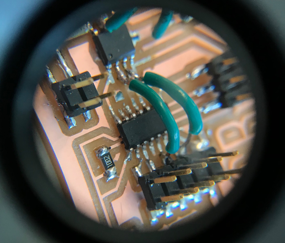
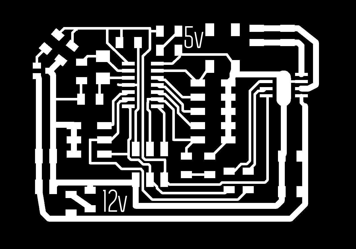
What I had stumbled upon was an accidental step-response sensor! I had forgotten to add a pullup resistor to the button pin, and so the whole board was acting like a step response sensor. You can see in the video above that whenever my hand came close to the back of the board, the button pin would read 'LOW' and the LED would be lit. Kind of neat, actually, but not the behavior I wanted. So I added a 10k pullup resistor to the board:
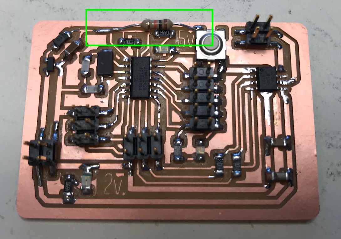
I also updated my board files to add the resistor (it is shown in the red and black image above, and reflected in the EAGLE files linked below After that, the button behaved as expected, and I was able to move on.
I wrote a sketch to use the button to toggle through some pre-set forward speeds (off, slow, medium, fast) and then the same speeds, but in the reverse direction (slow, medium, fast). It worked pretty well:
14_motor_control_dc from Greg Buckland on Vimeo.
Here's the code:
//this one toggles through a preset list of speeds in one direction
//and then toggles through the speeds in the other direction
//each button press advances through the list:
//[off, slow, medium, fast, off, slow-reverse, medium-reverse, fast-reverse]

#define in1 6
#define in2 7
#define buttonPin 0
#define off 0
#define slow 100
#define medium 175
#define fast 255

int counter = 0;
int counterMax = 8;
int buttonState = 0;

void setup() {
  pinMode(buttonPin, INPUT);
}

void loop() {
  // put your main code here, to run repeatedly:

  buttonState = digitalRead(buttonPin);   //read the button

  if (buttonState == LOW){    //if button is pressed
    delay(200);     //give user time to press and release button
    if (counter >= counterMax)    //if counterMax is reached
      counter = 0;      // reset counter to 0
    else
      counter++;      //otherwise, increment counter by 1
  }

  switch(counter){
    case 0:
      analogWrite(in1, off);
      analogWrite(in2, off);
      break;
    case 1:
      analogWrite(in1, slow);
      analogWrite(in2, off);
      break;
    case 2:
      analogWrite(in1, medium);
      analogWrite(in2, off);
      break;
    case 3:
      analogWrite(in1, fast);
      analogWrite(in2, off);
      break;
    case 4:
      analogWrite(in1, off);
      analogWrite(in2, off);
      break;
    case 5:
      analogWrite(in1, off);
      analogWrite(in2, slow);
      break;
    case 6:
      analogWrite(in1, off);
      analogWrite(in2, medium);
      break;
    case 7:
      analogWrite(in1, off);
      analogWrite(in2, fast);
      break;
    default:
      analogWrite(in1, off);
      analogWrite(in2, off);
      counter = 0;
      break;
  }

}
It also worked well (and is a little easier to see) with a heavily geared-down motor:
15_motor_control_geared_dc from Greg Buckland on Vimeo.
Serial Motor Control
The next step was to control the motor via the serial port, as a step towards controlling it via an application on the computer. First up I wanted to just get serial communications working. After reading some tutorials, I wrote the following code to count button presses and print the count to the serial monitor:
//Counts button presses and sends the count over serial connx

//The following lines of code modified from:
//https://www.hackster.io/porrey/easy-serial-on-the-attiny-2676e6

#include <SoftwareSerial.h>
// ***
// *** Define the RX and TX pins. Choose any two
// *** pins that are unused. Try to avoid D0 (pin 5)
// *** and D2 (pin 7) if you plan to use I2C.
// ***

#define TX    2   // PA2, pin 11, white cable
#define RX    3   // PA3, pin 10, green cable

// ***
// *** Define the software based serial port. Using the
// *** name Serial so that code can be used on other
// *** platforms that support hardware based serial. On
// *** chips that support the hardware serial, just
// *** comment this line.
// ***
SoftwareSerial Serial(RX, TX);

//end quoted code

#define buttonPin 0

int counter = 0;

void setup() {
  // put your setup code here, to run once:
  Serial.begin(9600);
  Serial.println("Starting serial communication...");
  Serial.print("Counter: "); Serial.println(counter);
  pinMode(buttonPin, INPUT);
  delay(200);
}

void loop() {
  // put your main code here, to run repeatedly:
  int buttonState = digitalRead(buttonPin);

  if (buttonState == LOW){
    delay(200);
    counter++;
    Serial.print("Counter: "); Serial.print(counter); Serial.println("");
  }
}
After the usual tinkering (ensuring correct connections, baudrate, etc.), I got it working well:
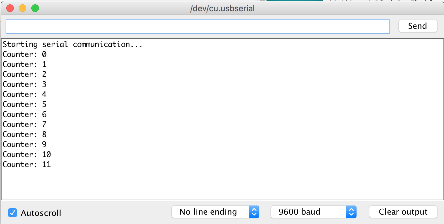
Now that I had serial communication working, I wanted to get the motor working via serial. Here's a simple code that takes a few inputs over serial and responds by changing the motor speed:
//Controls motor in one direction. Takes 'S', 'M', 'F', and 'O'
//corresponding to slow, medium, fast, and off
//uknown input defaults to off

//The following lines of code modified from:
//https://www.hackster.io/porrey/easy-serial-on-the-attiny-2676e6

#include <SoftwareSerial.h>
// ***
// *** Define the RX and TX pins. Choose any two
// *** pins that are unused. Try to avoid D0 (pin 5)
// *** and D2 (pin 7) if you plan to use I2C.
// ***
#define TX    2   // PA2, pin 11, white cable
#define RX    3   // PA3, pin 10, green cable

// ***
// *** Define the software based serial port. Using the
// *** name Serial so that code can be used on other
// *** platforms that support hardware based serial. On
// *** chips that support the hardware serial, just
// *** comment this line.
// ***
SoftwareSerial Serial(RX, TX);

//end quoted code

//Following code adapted from:
//https://processing.org/tutorials/electronics/

char val;             // Data received from the serial port
int motorpin = 6;     // define motorpin (this will be in1 on A4953)
bool newData = false; // store whether there's new serial data or not


void setup() {
  Serial.begin(9600);                  // Start serial communication at 9600 bps
  Serial.println("Go");
}

void loop() {
  if (Serial.available() > 0) {            // If data is available,
    val = Serial.read();               // read it and store it in val
    newData = true;
  }
  if ((val == 'S' || val == 's') && newData) {                    // If 'S' was received,
    analogWrite(motorpin, 75);        // turn the motor on at slow speed
    Serial.println("Slow");
  } else if ((val == 'M' || val == 'm') && newData){
    analogWrite(motorpin, 155);
    Serial.println("Med");
  } else if ((val == 'F' || val == 'f') && newData){
    analogWrite(motorpin, 255);
    Serial.println("Fast");
  } else if ((val == 'O' || val == 'o') && newData){
    analogWrite(motorpin, 0);
    Serial.println("Off");
  } else if (newData){                    // If S, M, or F was not received
    analogWrite(motorpin, 0);          // turn the motor off
    Serial.println("Use 'S', 'M', 'F', or 'O'");
    Serial.println("Shutting down");
  }
  newData = false;
  delay(100);                          // Wait 100 milliseconds for next reading
}
It worked pretty well! I didn't take a video of this motor response, but here is the serial monitor:
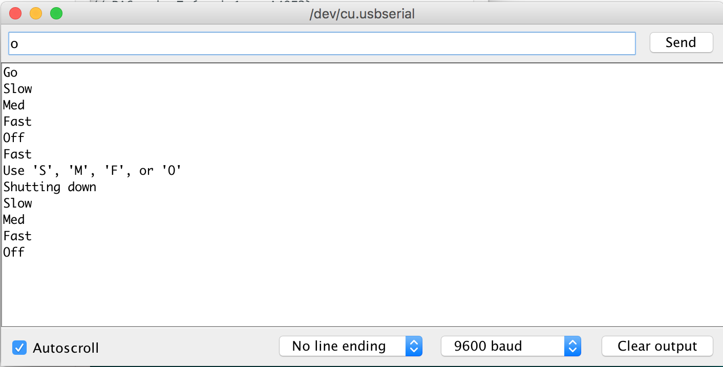
Next I did a version that could also take 'r' and 'a' to change the motor direction. Then you can send 'af' for "ahead fast" or 'rs' for "reverse slow":
// This version includes forward and reverse direction
// still takes serial input 's','m', 'f', 'o'
// now takes 'r' for reverse and 'a' for ahead
// also flashes blue LED when data sent/received

#include <SoftwareSerial.h>

#define TX    2   // PA2, pin 11, white cable
#define RX    3   // PA3, pin 10, green cable
#define bluePin 4 // PA4, pin 9, blue led
#define in1 6;  // PA6, pin 7 (-> in1 on A4953)
#define in2 7;  // PA7, pin 6 (-> in2 on A4953)

SoftwareSerial Serial(RX, TX);


//Following code adapted heavily from:
//https://processing.org/tutorials/electronics/
//includes excerpts from:
//http://forum.arduino.cc/index.php?topic=288234.0

char val;             // Data received from the serial port
char prevVal;         // the previous character received
bool newData = false; // store whether there's new serial data or not
int motorPin = in1;   // start the motor in the 'ahead' direction
int offPin = in2;

void setup() {
  Serial.begin(9600);     // Start serial communication at 9600 bps
  Serial.println("Go");   //signal to terminal that board is ready
  pinMode(bluePin, OUTPUT); //set bluepin for output
  analogWrite(motorPin, 0); //ensure motor is off
  analogWrite(offPin, 0);   //ensure reverse motor also off
}

void loop() {
  if (Serial.available() > 0) {            // If data is available,
    prevVal = val;                //store the previous speed-related serial character
    val = Serial.read();               // read it and store it in val
    newData = true;
    digitalWrite(bluePin, HIGH);
  }
  if (newData){   // if new data is received, check what it is
    if (val == 'A' || val == 'a'){
      analogWrite(offPin, 0);
      analogWrite(motorPin, 0);
      motorPin = in1;
      offPin = in2;
      Serial.println("Ahead");
    }
    else if (val == 'R' || val == 'r'){
      analogWrite(offPin, 0);
      analogWrite(motorPin, 0);
      motorPin = in2;
      offPin = in1;
      Serial.println("Reverse");
    }
    else if (val == 'S' || val == 's') {                    // If 'S' was received,
      analogWrite(offPin, 0);           // turn offPin off (as always)
      analogWrite(motorPin, 75);        // turn the motor on at slow speed
      Serial.println("Slow");
    } else if (val == 'M' || val == 'm'){
      analogWrite(offPin, 0);
      analogWrite(motorPin, 155);
      Serial.println("Med");
    } else if (val == 'F' || val == 'f'){
      analogWrite(offPin, 0);
      analogWrite(motorPin, 255);
      Serial.println("Fast");
    } else if (val == 'O' || val == 'o'){
      analogWrite(offPin, 0);
      analogWrite(motorPin, 0);
      Serial.println("Off");
    } else {                    // If S, M, or F was not received
      analogWrite(offPin, 0);
      analogWrite(motorPin, 0);          // turn the motor off
      //Serial.println("Use 'S', 'M', 'F', 'O', 'R', 'A'");
      Serial.println("Shutting down");
    }
  }

  delay(100);    // Wait 100 ms for next reading
  digitalWrite(bluePin, LOW);   //turn off blue LED
  newData = false;    //reset newData boolean
}
This version also worked pretty well, and could be used to receive serial commands from an application interface. But I wanted more granular control, so I did some research and found the Arduino Serial.parseint() function, which reads a string from the serial buffer until it parses a valid integer. I wanted to be able to send an integer between 0 and 255 to set the pulse width modulation and control the motor speed in a more "analog" way. I thought about it for a bit, and decided the cleanest implementation was to simply look for an integer between -255 and 255, with 0 meaning "stop" and negative values meaning reverse direction, so I wrote the following script:
// This version includes forward and reverse direction
// parses integers from serial buffer and sets as motor output
// negative integers lead to reverse direction, 0 turns motor off
// looks for values between -255 and 255. Numbers outside this range are
// interpreted as full speed (ahead for positive and reverse for negative)

// this version is for geared motor

#include <SoftwareSerial.h>

#define TX    2   // PA2, pin 11, white cable
#define RX    3   // PA3, pin 10, green cable
#define bluePin 4 // PA4, pin 9, blue led
#define in1 6;  // PA6, pin 7 (-> in1 on A4953)
#define in2 7;  // PA7, pin 6 (-> in2 on A4953)

SoftwareSerial Serial(RX, TX);

//Following code adapted heavily from:
//https://processing.org/tutorials/electronics/
//includes excerpts from:
//http://forum.arduino.cc/index.php?topic=288234.0

//char val;             // Data received from the serial port //unused in this version
//char prevVal;         // the previous character received
bool newData = false; // store whether there's new serial data or not
int motorPin = in1;   // start the motor in the 'ahead' direction
int offPin = in2;
int power = 0;        //start the motor at 0 power

void setup() {
  Serial.begin(9600);       //Start serial communication at 9600 bps
  Serial.println("Go");     //signal to terminal that board is ready
  pinMode(bluePin, OUTPUT); //set bluepin for output
  analogWrite(motorPin, 0); //ensure motor is off
  analogWrite(offPin, 0);   //ensure reverse motor also off
}

void loop(){
  if (Serial.available() > 0) { //if serial buffer has data
    power = Serial.parseInt();  //parse the next valid integer from serial buffer
    power = constrain(power, -255, 255); //constrain speed to valid PWM range
    if (power > 0){   //if the power integer is positive
      motorPin = in1; //set the motor direction to forward
      offPin = in2;
    }
    else if (power < 0){  //if power int is negative
      motorPin = in2;     //set the motor to reverse
      offPin = in1;
    }
    power = abs(power);
    newData = true;             //note the presence of new data
    digitalWrite(bluePin, HIGH);  //blink the blue LED to alert user to new data
  }
  if (newData){   //if new serial data came in
    analogWrite(offPin, 0);   //turn off offPin
    analogWrite(motorPin, power);   //send power PWM to motorPin
    Serial.print("Power: "); Serial.println(power);
  }

  delay(50);    // Wait 50 ms for next reading
  digitalWrite(bluePin, LOW);   //turn off blue LED
  newData = false;    //reset newData boolean

}
This code works quite well. You can even send it a random string and it will parse out any valid integer and set the motor speed to it. If no valid integer is found, it shuts the motor off (a good feature, I think). The only real challenge, I think, is that the parseInt() function is noticeably slow (it takes the motor probably 0.5 seconds to respond to a serial command). This will be fine for my purposes, but if I needed better performance/response time, I might have to go in and write some lower level C-code to parse the serial data. I'm guessing it would be possible to send a single 8-bit byte over serial, corresponding to the PWM power, followed by a 1 for 'forward' and a 0 for 'reverse', or something like that. A task for another day.
Application Programming
At first I thought I would get an application setup via Processing, but I had some trouble getting the serial connection to work between Processing and my ATtiny. (Some of the tutorials on on Processing were helpful for wrapping my head around interface between arduino/microcontroller and an application, especially this page.) I knew that I had gotten python talking to a board via pyserial a couple weeks ago , and I have some experience coding in python, so I thought I'd give that a go.
I started by brushing up on my python with the Codecademy tutorials. Once I had reminded myself about the syntax and basically how python works, I looked up some Pyserial documentation. I found this page and this video in combination gave me most of what I needed to dive in.
I had installed Pyserial back in Week 10 to talk to my ADXL board. I wanted to first setup a test connection in a python terminal, so I booted up a terminal and typed python -m serial.tools.list_ports to find the serial port I would be using. It returned:
/dev/cu.BHS-530-SerialPort
/dev/cu.BHS-530-SerialPort-1
/dev/cu.Bluetooth-Incoming-Port
/dev/cu.usbserial
4 ports found
I happen to know that the 4th one listed /dev/cu.usbserial was the right port so I typed python to load up the python interpreter. As per the tutorials linked above, I typed the following:
Greg$ python
Python 2.7.10 (default, Oct 23 2015, 19:19:21)
[GCC 4.2.1 Compatible Apple LLVM 7.0.0 (clang-700.0.59.5)] on darwin
Type "help", "copyright", "credits" or "license" for more information.
>>> import serial
>>> s = serial.Serial('/dev/cu.usbserial', 9600)
>>> s.is_open
True
>>> s.write('255')
3
At this point the motor responded full speed in the forward direction (huzzah!)
>>> s.write('150')
3
Here the motor responded about half speed in the forward direction (huzzah!)
>>> s.write('0')
1
Here the motor stopped (huzzah!)
>>> s.write('-150')
4
Now the motor responded half speed in the reverse direction (huzzah!)
>>> s.write('-255')
4
And now it was full speed in the reverse direction (hip hip, huzzah!)
At this point I was very excited because the serial connection between python and my board was working great, I just needed to write a little program and interface to send these control signals via a GUI, rather than at the command line.
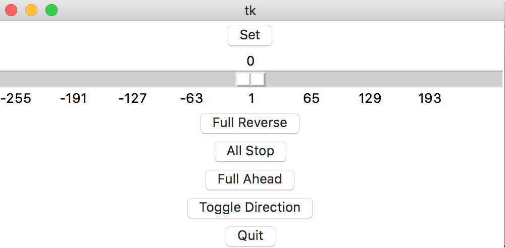
I knew I wanted to use the Tkinter GUI system for python so I spend some time with some Tkinter documentation and tutorials. I got together a simple interface using some basic Tkinter widgets. My code:
##
##  This section sets up the user interface
##
master = Tk()
b5 = Button(master, text='Set', command=update)
b5.pack()
s1 = Scale(master, from_=-255, to=255, length=500, tickinterval=64, orient=HORIZONTAL)
s1.pack()
s1.set(0)
b1 = Button(master, text='Full Reverse', command=full_reverse)
b1.pack()
b2 = Button(master, text='All Stop', command=all_stop)
b2.pack()
b3 = Button(master, text='Full Ahead', command=full_ahead)
b3.pack()
b4 = Button(master, text='Toggle Direction', command=toggle_direction)
b4.pack()
b6 = Button(master, text='Quit', command=quit)
b6.pack()

mainloop()
Led to the following interface:
It was surprisingly easier than I thought - especially after the myriad problems I had along the way (shoddy boards, serial connection troubles, processing not working, etc.). Now I just needed to pack this interface into a program that would actually do the things the button said. Here's my whole python script:
# Script for controlling DC motor using ATtiny44 and A4953 H-bridge chip

##
##  This section sets up the serial connection and imports
##  Tkinter  (GUI)functionality
##
import serial
from Tkinter import *

#Change this path to match your port:
ser = serial.Serial('/dev/cu.usbserial', 9600)

##
##  This section defines all the functions I will
##  call in my Tkinter interface
##
def all_stop():
    s1.set(0)
    update()
    print("Answering 'All Stop'!")

def full_ahead():
    s1.set(255)
    update()
    print("Answering 'Full Ahead'!")

def full_reverse():
    s1.set(-255)
    update()
    print("Answering 'Full Reverse'!")

def toggle_direction():
    dir = -s1.get()
    s1.set(dir)
    update()
    print("Answering 'Toggle Direction'!")

def update():
    ser.write(str(s1.get()))

def quit():
    try:
        ser.write('0')
    except:
        print("Something wrong with serial connection")
    print("Exiting program")
    exit()

##
##  This section sets up the user interface
##
master = Tk()
b5 = Button(master, text='Set', command=update)
b5.pack()
s1 = Scale(master, from_=-255, to=255, length=500, tickinterval=64, orient=HORIZONTAL)
s1.pack()
s1.set(0)
b1 = Button(master, text='Full Reverse', command=full_reverse)
b1.pack()
b2 = Button(master, text='All Stop', command=all_stop)
b2.pack()
b3 = Button(master, text='Full Ahead', command=full_ahead)
b3.pack()
b4 = Button(master, text='Toggle Direction', command=toggle_direction)
b4.pack()
b6 = Button(master, text='Quit', command=quit)
b6.pack()

mainloop()
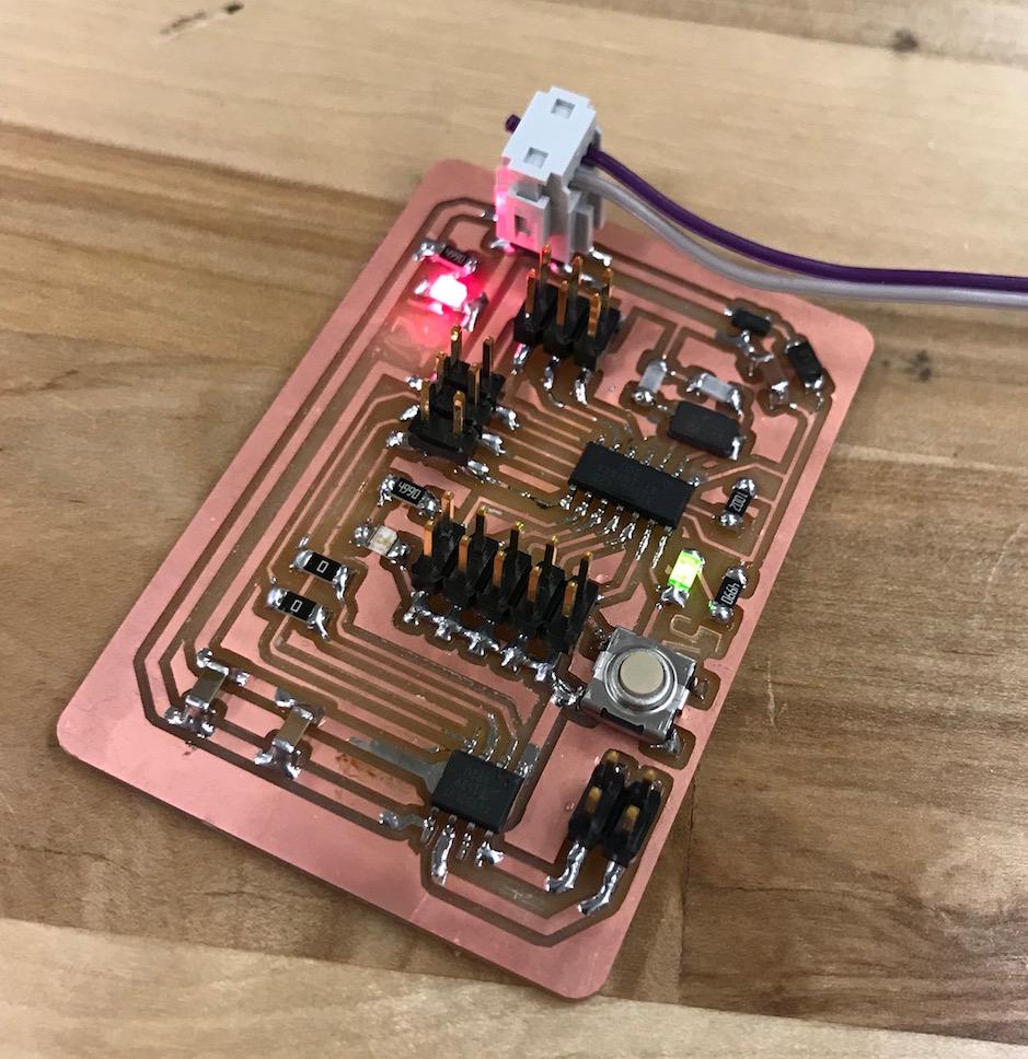
Here's what it looks like when it's all hooked up and running:
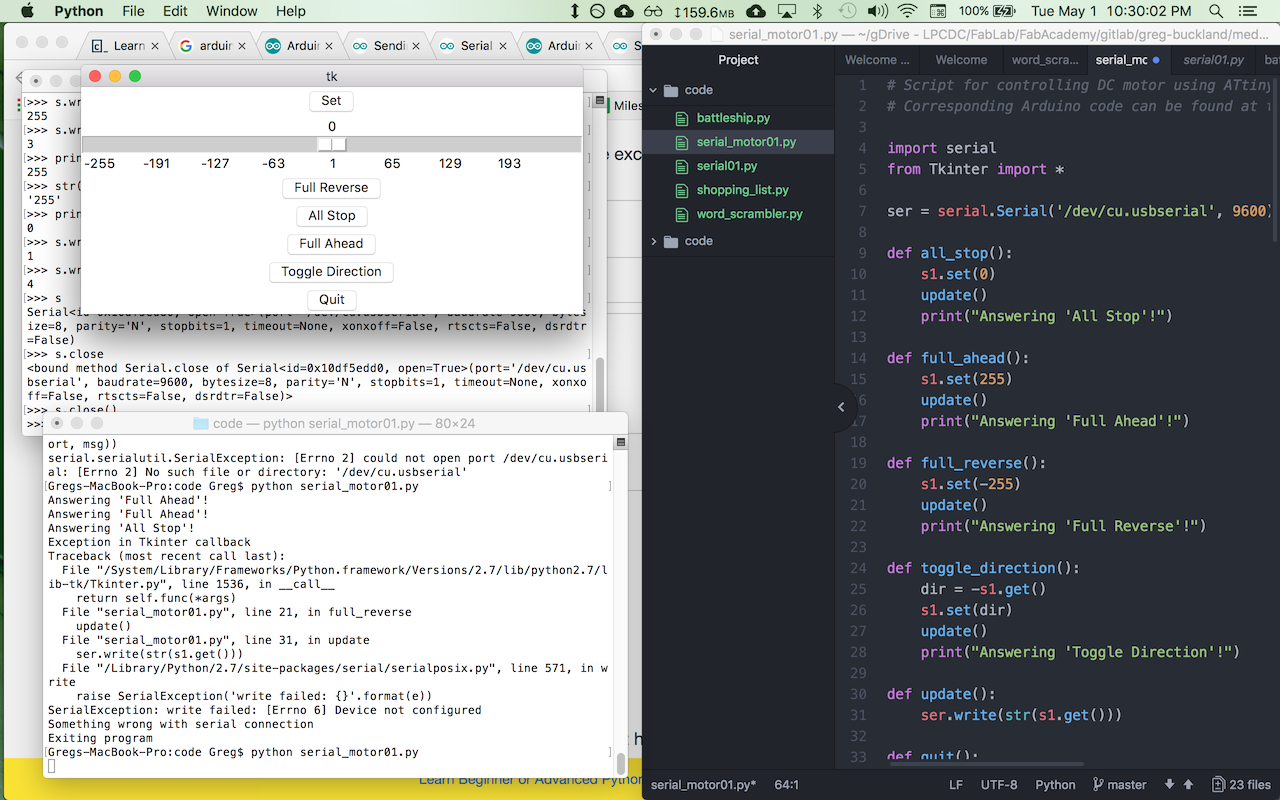
At long last, I got my program working. Here it is in action:
17_interface_working from Greg Buckland on Vimeo.
I realize this is quite a basic interface, but it works. In the spirit of spiral development, I decided to get something simple working, and I will plan to move on from there in future weeks (e.g. when I work on my final project).
Design Files
DC motor board file v05 (.BRD file)
DC motor schematic file v05 (.SCH file)