Computer Controlled Machining

Introduction
For the assignment we were asked to "make something big". So, since I am definitely not the first one who does not understand what "something big" means, I went to a FAQ in FabAcademy Student book. There it is said "big enough to show the possibilities of CNC machining - drill, pocket, dogbones, nesting, etc." As a Group Assignment we were asked to test runout, alignment, speeds, feeds, and toolpaths for our FabLab machine.
Below you can read about two designs, first is more "theoretical" about some lifehacks, that I figured out while working on design and preparing it for the machine. The second one is more "practical", since it is more about my final project. So, since the second one is more important, I milled it first. As for the laptop stand, I think I will mill it in a close future, since I really need such a stand and such a simple design should not take a lot of time because I am now experienced with the machine.
Design V1.0
Since this is not a week about design, I decided to use this design of Laptop Stand Design from Autodesk Fusion 360. The tutorial how to design it can be found here. This is how the design looks like:

Preparation for the Milling
The "round angles" is very common problem while using any kind of milling machines. This problem is about milling itself, since the machine cannot actually mill right angle, it is hard to make a press-fit:
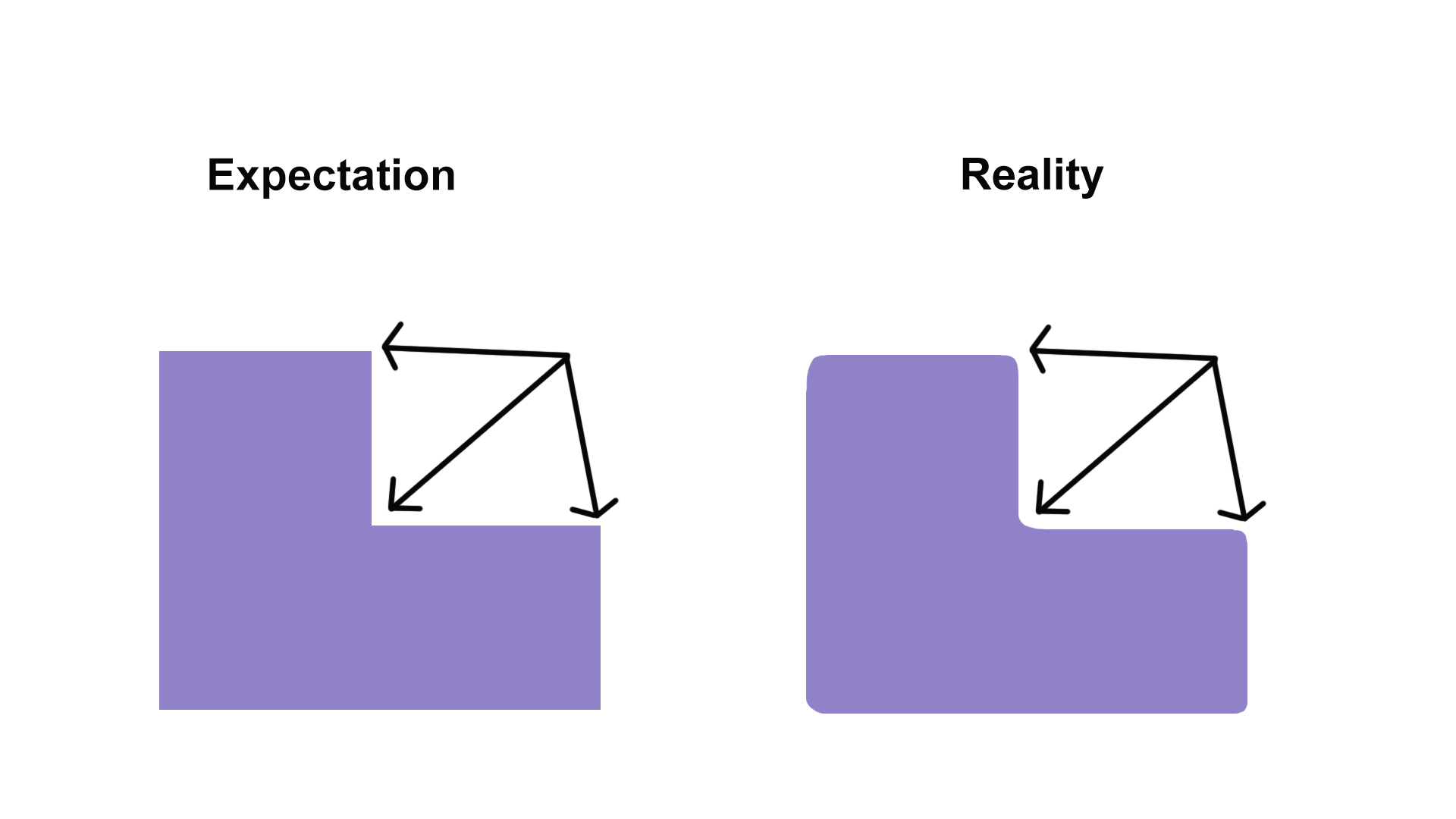

I also used simulation to see how it will be drilled.


Actually, there are more method of improvement. For example, just make holes bigger and rounder from the design:
.png)
Design V2.0
I also thought about creating a design for my Final project. I think, that making a planter itself as well as lightstand is a good idea. I used Autodesk Fusion 360 for making the design:

This is quite simple design (a bit harder than creating a simple box, that you can find here), but making connectors was not so obvious. Here is a step-by-step instruction, how to do it(video tutorial can be found here).


All the design files can be found at the very end of this documentation.
CAM processor of Fusion360
Next step after creating a model is CAM. For that you need to change from Model view to Cam: 
Then you need to prepare a SETUP. Make sure that Z-axis goes to the thickness direction.

Next Step during my work was to prepare a Contour.

This was a hard step, because choosing proper contour selection was not easy. Here you can see what solution I found:

During this stage (CAM) you actually set the parameters of the machine:
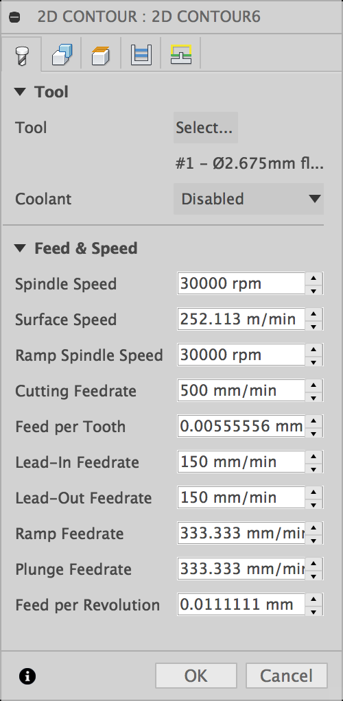
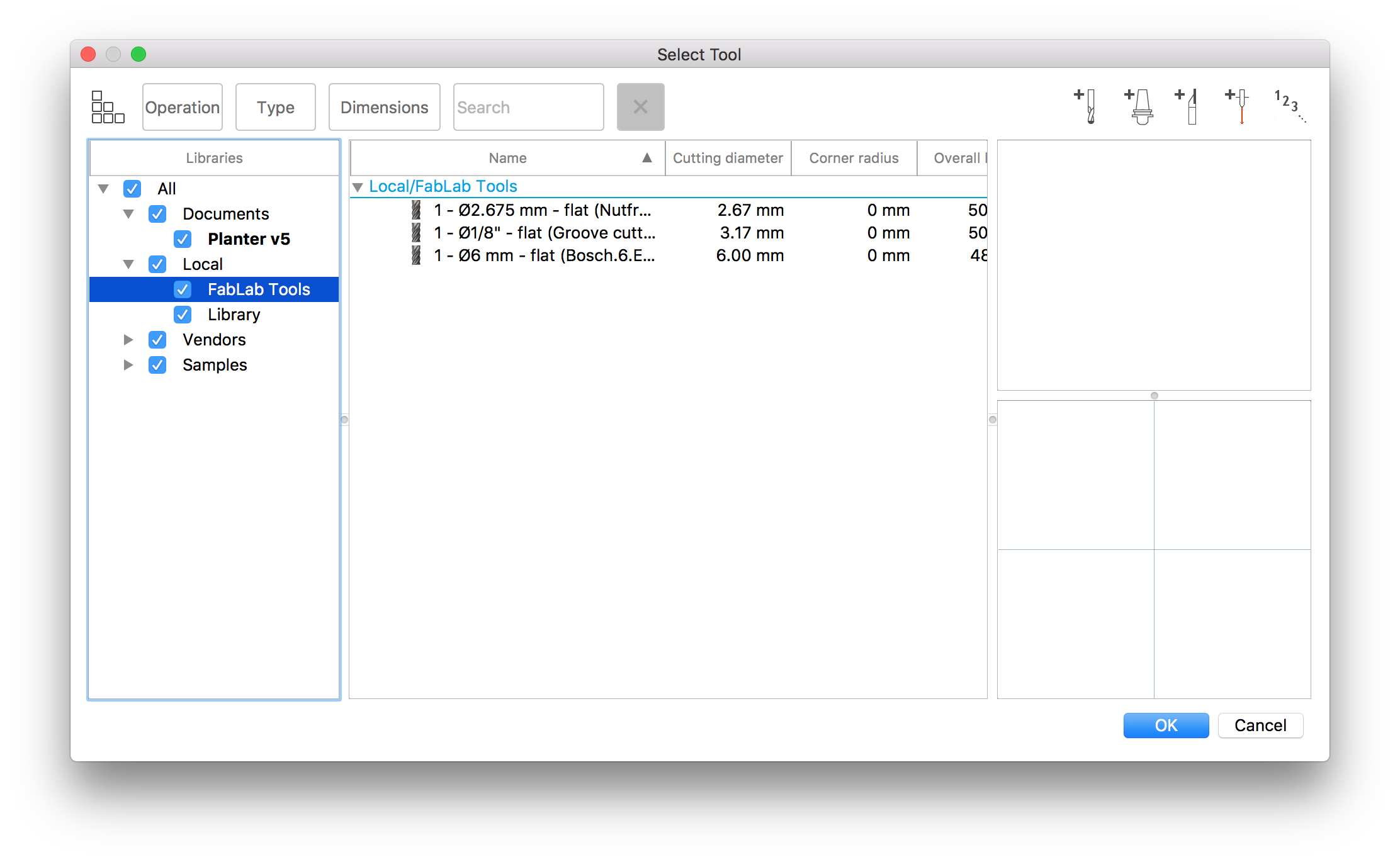
Here you select a specific tool. In our fab lab we have a special library with all our tools:
Here is a bit more explanation what each parameter mean:
- Spindle Speed - The rotational speed of the spindle.
- Surface Speed - The spindle speed expressed as the speed of the tool on the surface.
- Ramp Spindle Speed - The rotational speed of the spindle when performing ramp movements.
- Cutting Feedrate - Feed used in cutting moves.
- Feed per Tooth - The cutting feedrate expressed as the feed per tooth.
- Lead-In Feedrate - Feed used when leading in to a cutting move.
- Lead-Out Feedrate - Feed used when leading out from a cutting move.
- Ramp Feedrate - Feed used when doing helical ramps into stock.
- Plunge Feedrate - Feed used when plunging into stock.
- Feed per Revolution - The plunge feedrate expressed as the feed per revolution.
For all these parameters I used the predetermined values(predetermined from tool), except for the Cutting Feedrate, which I tried different. With the value of 200 it starts burn, so the speed 500 seems to be ideal, so I used it.
After Preparing all the design settings, it is a nice idea is to always check how it would be cut in Simulation section. This will give you the understanding how the cut will go and can help you in finding some mistakes. Next and last step here is to create a Post process. Here you generate .nc file which will be used in future:

UCCNC software Stepcraft
For the stepcraft machine we have a special software to move to drilling head and start milling. Here you can see a really interesting interface of it:
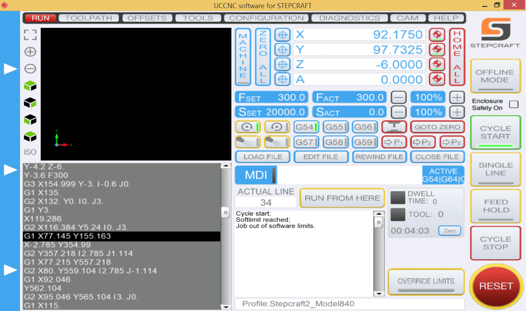
To be able to start milling follow these steps:
- Load the file you saved on your computer before into the software by clicking on the button 'Load file'
- Start moving your drill head with the arrow keys on your keyboard to a position where the zero coordinate of your model is. Then click the button 'Zero All'
- If the object fits onto the material move your drilling head onto the material in the Z-axis and press 'Zero all' again.
- Move your drill head up again. Around 1cm from the material is fine.
- Press the button 'Cycle Start' to start your mill process
Cutting
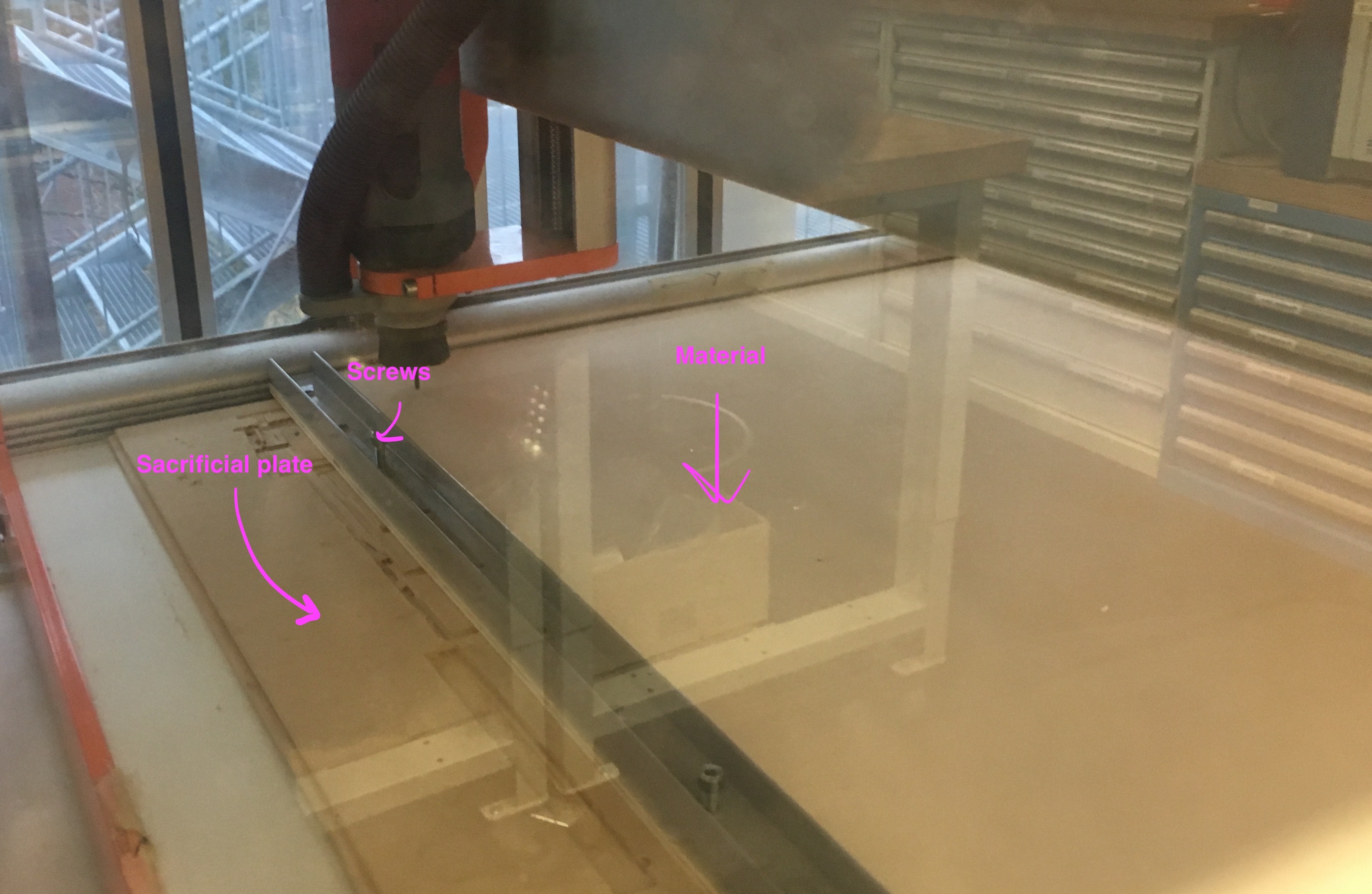
In order to fix the material we use two metal beams(one of them you can see in the picture below). They have multiple holes for putting screws in them in order to fix it. In order not to damage the cnc bed if the milling head drills through your piece of wood we use the sacrificial plate. This is basically used piece of material(wood), that we put under our material.
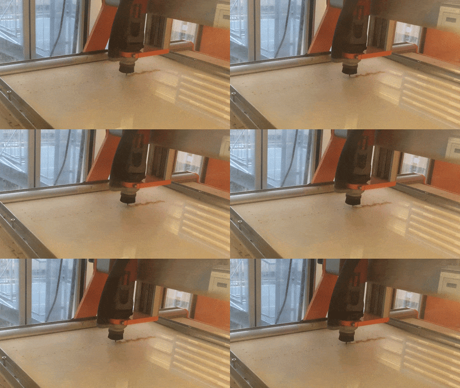
Here is the process of milling:
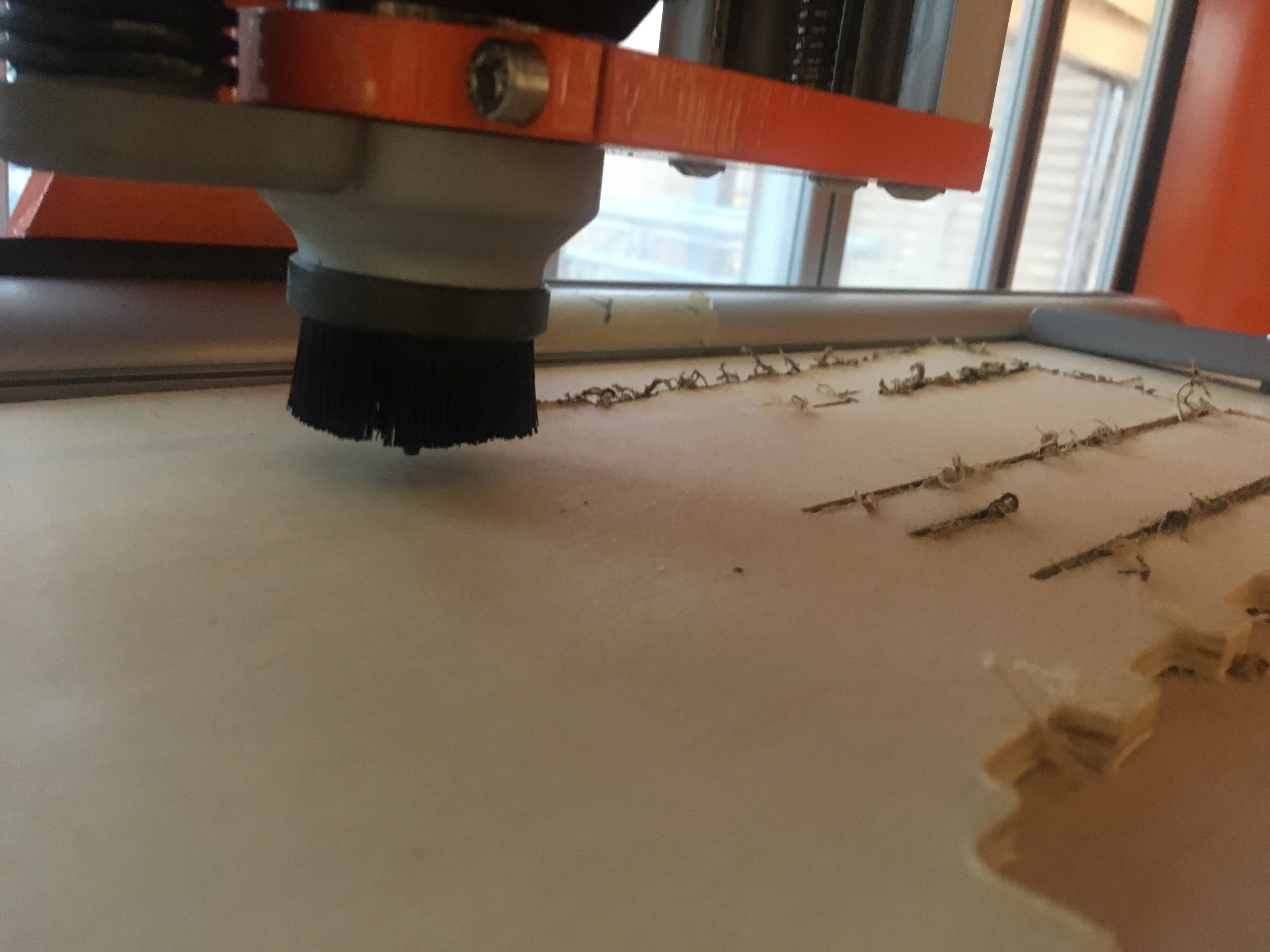
But anyway, during the process there was a plethora of mistakes. Sometimes the drilling head was brocken:
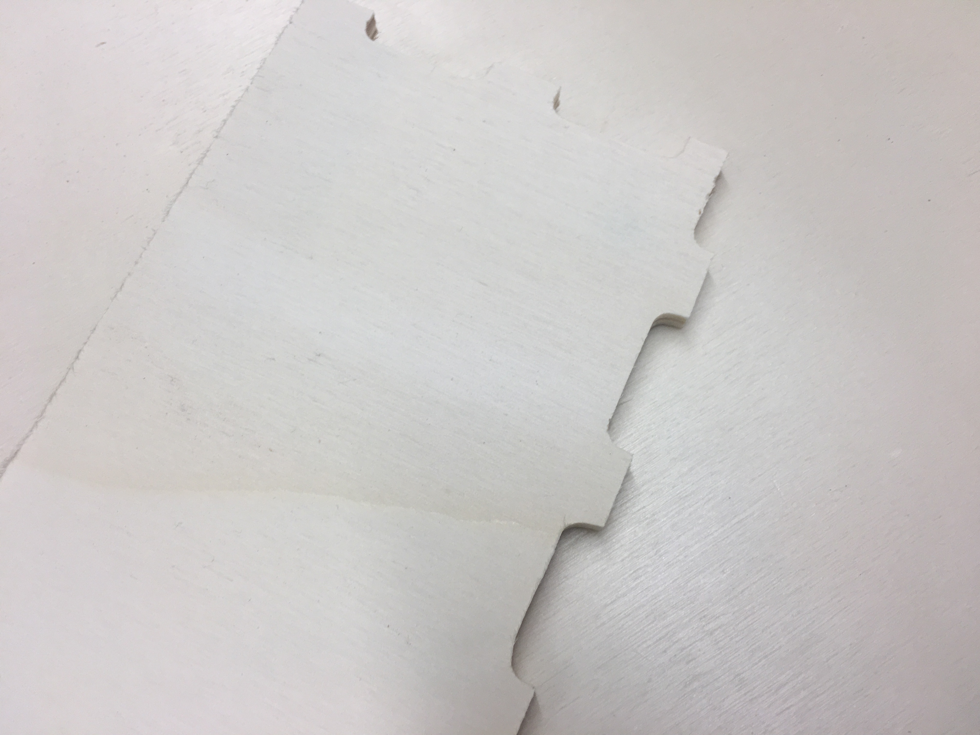
Or sizes were 2 mm larger. This happened because of the size of the head, offset should solve the problem.

After changing the head and using simular settings, the design was totally different. But actually, the mistake was in choosing the contour. Accidentally I choose the inner one, that is why the proper joints were in the external part of the material.
Or it did not cut through. The explanation here is a machine setup mistake.

At the end I had to do the assembling of all my parts together:


So, finally I got that:


Files
Download .f3d file of my Planter Design
Download .dxf file of my Planter Design bottom part
Download .dxf file of my Planter Design side 1 part
Download .dxf file of my Planter Design side 2 part
Download .dxf file of my Planter Design side 3 part