Networking and Communications
Network & Communications
This weeks assignment was about designing and building a wired &/or wireless network connecting at least two processors. I decided to do something, that would be useful for my future project - an wireless connection between my smart planter and my computer, where I will develop an application that will show, when the water tank is empty and when it is full.
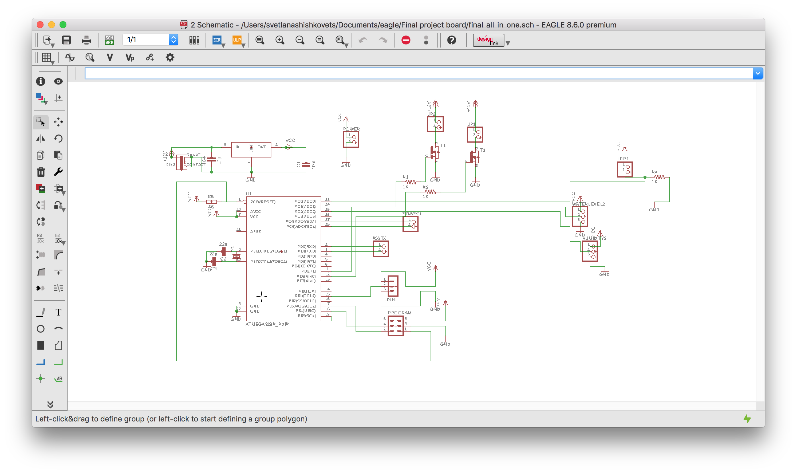
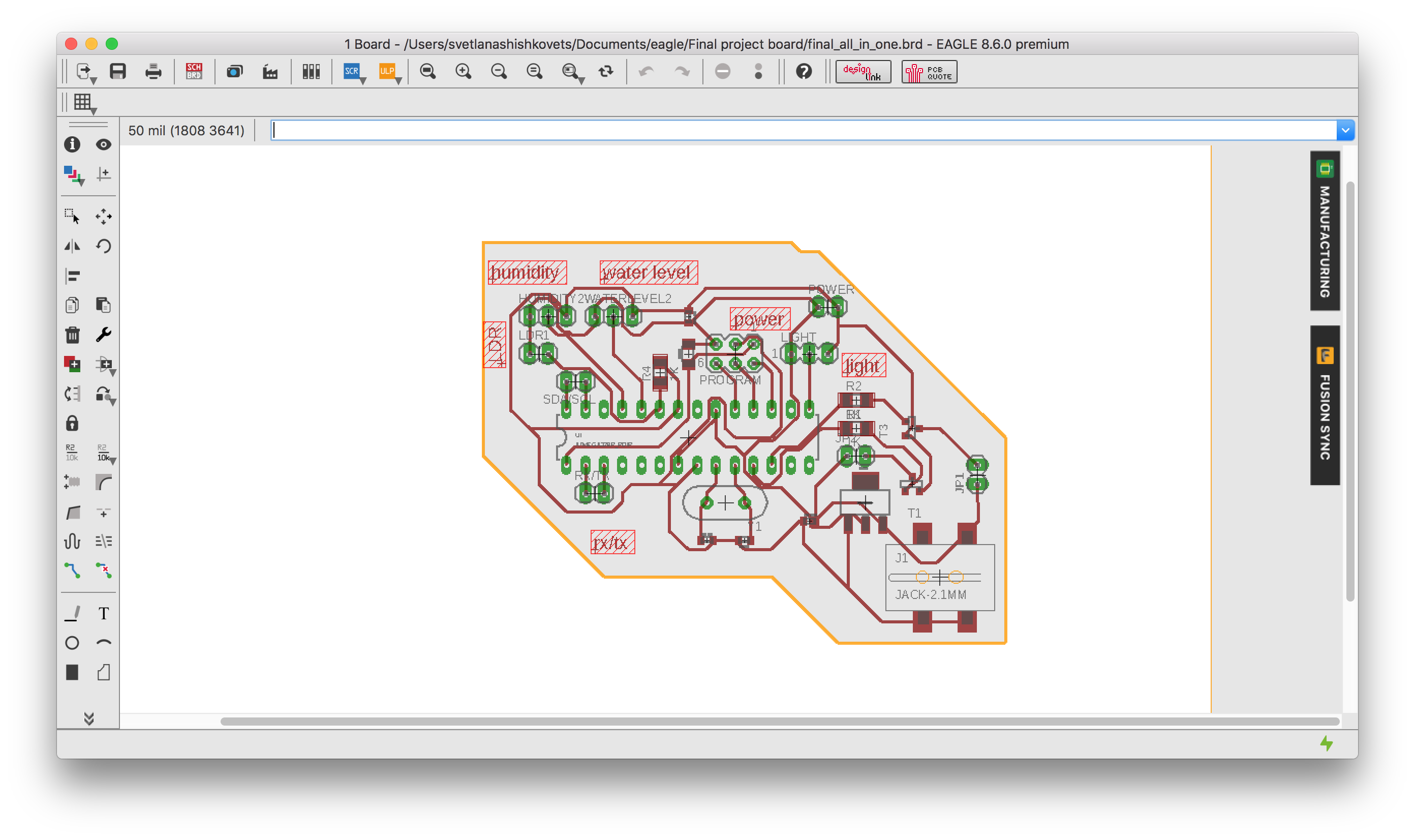
A quick intro: for that assignment I used my final presentation board. As I already explained in Output & Input assignment, this board will control all the Output devices(water pump, LED strip, WS2812) depending on input sensors(water level, humidity & light). Here is the schematic and board:
Serial communication between board ann laptop using Bluetooth
I used an HC05 bluetooth module (Datasheet ). The module uses a serial connection over the RX and TX pin and my final board processor ATmega328 has such a pins, there should be no problem. Here is an instruction, how to set and connect the bluetooth module:
- Connect EN pin to 5V (high level) and GND to ground
- Hold RESET button while powering on
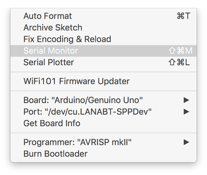
- Use Arduino serial monitor to write AT commands to bluetooth module and configure name, password and etc(All the commands can be found in datasheet above)
- Repower without EN pin and without holding RESET button and connect to bluetooth device normally
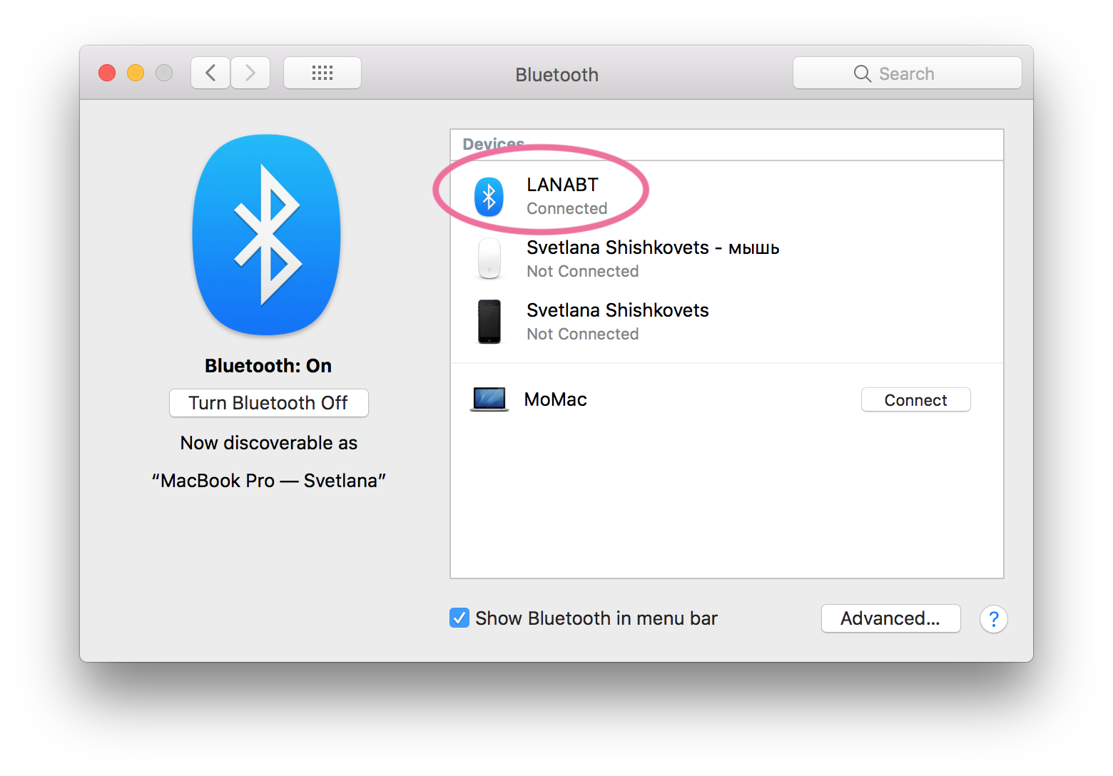
After that I could find bluetooth on my laptop and connect it:
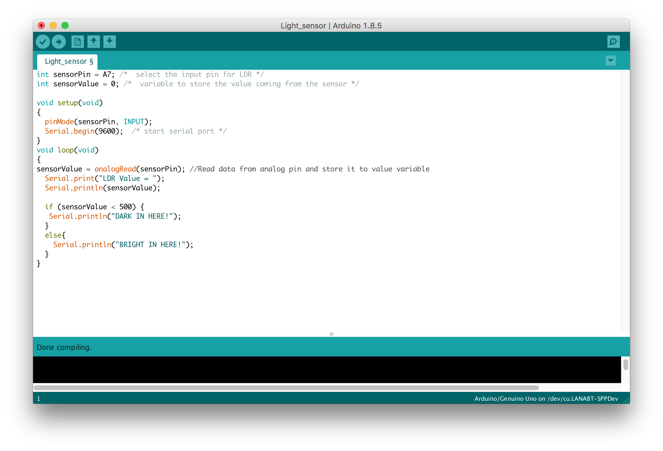
After that I programmed my board using serial communication:
So now, if I will open serial Monitor for a device - Bluetooth, I will see what bluetooth module receives :
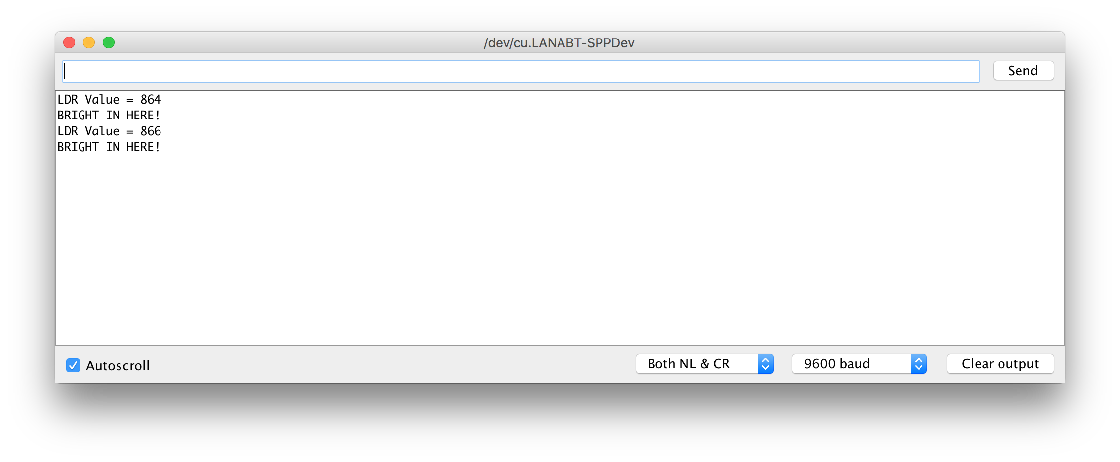
For application programming I will use the same serial.print as above. I plan to show two states of my water reservoir: empty and full. For that I will send 0 or 1 in serial communication. For more information check Application assignment .
Serial communication between two boards
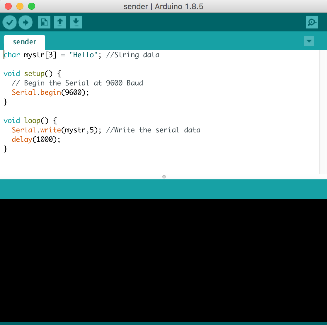
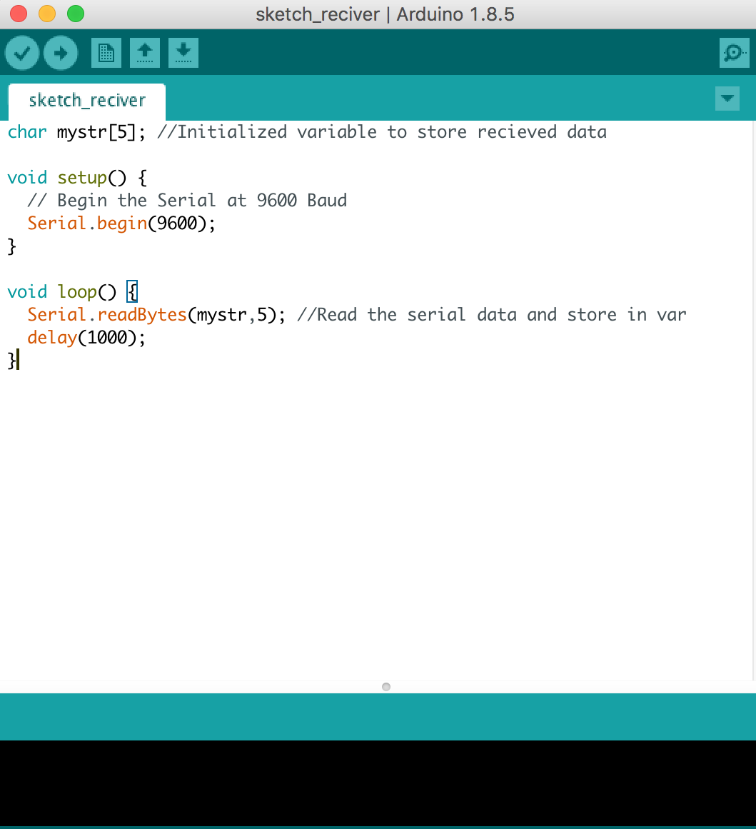
I also did serial communication between two boards(using wires). For that it has to be a common ground between the two boards(that means that ground of boards are connected) or else it will not function properly. Also, note that TX goes to RX and RX goes to TX. Here is the code for sender board and receiver one:
I2C communication
If you need to have communication between more, than two board, there is also a solution for you. In my project I did not need it, but I studied theory just in case (and for future). So, the great solution for that is I2C communication bus. The I2C communication bus is very popular and broadly used by many electronic devices because it can be easily implemented in many electronic designs which require communication between a master and multiple slave devices or even multiple master devices. Here is a sample scheme of I2C connection bus:
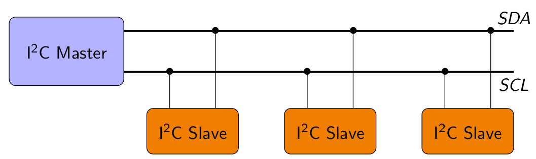
The two wires are called Serial Clock (or SCL) and Serial Data (or SDA). The SCL line is the clock signal which synchronize the data transfer between the devices on the I2C bus and it’s generated by the master device. The other line is the SDA line which carries the data.
Next step is code. For I2C communication Wire Library is needed. Here is a quick intro to the main functions of the library :
- Wire.begin() function will initiate the Wire library.
- Wire.beginTransmission() function which will begin the transmission to the particular sensor.
- Wire.write() function will ask for the particular data (in order to "send" it).
- Wire.endTransmission() function will end the transmission and transmit the data from the registers.
- Wire.requestFrom() function will request the transmitted data.
- Wire.available() function will return the number of bytes available for retrieval and if that number match with our requested bytes.
- Wire.requestFrom() function will read the bytes from the two registers.
So, here is an example how to make an I2C communication between two boards(more can be added). We will program one master board to command the other slave board to blink its built-in LED once or twice depending on the received value. The following code is split in two parts: the master code and the slave code, which run on two different microcontrollers. Master code:
                #include "Wire.h"
int x = 0;
void setup() {
  // Start the I2C Bus as Master
  Wire.begin();
}
void loop() {
  Wire.beginTransmission(9); // transmit to device #9
  Wire.write(x);              // sends x
  Wire.endTransmission();    // stop transmitting
  x++; // Increment x
  if (x > 5) x = 0; // `reset x once it gets 6
  delay(500);
}
Slave code that interprets the characters sent from the master:
                #include "Wire.h"
int LED = 13;
int x = 0;
void setup() {
  // Define the LED pin as Output
  pinMode (LED, OUTPUT);
  // Start the I2C Bus as Slave on address 9
  Wire.begin(9);
  // Attach a function to trigger when something is received.
  Wire.onReceive(receiveEvent);
}
void receiveEvent(int bytes) {
  x = Wire.read();    // read one character from the I2C
}
void loop() {
  //If value received is 0 blink LED for 200 ms
  if (x == '0') {
    digitalWrite(LED, HIGH);
    delay(200);
    digitalWrite(LED, LOW);
    delay(200);
  }
  //If value received is 3 blink LED for 400 ms
  if (x == '3') {
    digitalWrite(LED, HIGH);
    delay(400);
                }