Week 19. Project presentation. Assignment of the week is to document a final project that integrates the range of units covered, answering:
- What does it do?
- Who's done what beforehand?
- What did you design?
- What materials and components were used?
- Where did they come from?
- How much did they cost?
- What parts and systems were made?
- What processes were used?
- What questions were answered?
- How was it evaluated?
- What are the implications?
What does it do?
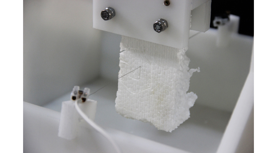
The prototype can be used as a foam cutter for example for modelling and casting objects. It should be able to cut fairly precise 2D-shapes, including sharp corners and holes with bores or models for cogs. (Picture: Francesca Perona.)
Who's done what beforehand?
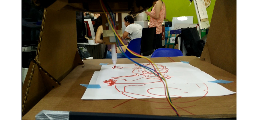
It looked like it would be hard to achieve custom mechanics and working CNC-machine. Especially when machine building week was delayed until so close to the end of the academy. Therefore I was thinking of using MIT's linear cardboard stages for the job. However, making a fairly similar machine as group effort at the machine building week build my confidence to do something more. Also, during the same week, I got familiarized with the firmware called GRBL. I designed electronics for it based on Fab in a Box, Arduino Uno, and FTDI-cable version of Gabriel Tanner Pasetti. I calculated new values to the components of the Allegro motor driver according to the components in the fab inventory and tested the driver. Gabriella Gardosi designed a motor driver shield board using this proto as a base. The GRBL firmware was ready almost out of the box and the GUI called GRBL Controller worked out of the box. I tested electronics, firmware and GUI with an example G-code and the machine we made on the machine building week. It draw a circle:
What did I design?
Custom mechanics: I designed custom mechanics for the CNC-machine from the scratch, according to my original sketch. They are drawn with SolidWorks for Nema17 stepper motors and 8 mm lead screws and guides. The model of the motor came from GrabCAD. For unknown reason I couldn't get any general libraries to work in SolidWorks, such as bearings, screws, etc. Therefore all but those stepper motors are drawn by me. The bearings are pocketed and selected screws or nuts are sunk to the walls of the frame to utilize the full working area. The frame is designed to be milled and all the pockets are on the same side of the plate to avoid double sided milling. I put tabs in Rhino Cam on the peaces not having screw holes . The cross section of the X- and Y-axis has pockets for six linear bearings and nuts for the lead screws. Motor connector of the Y-axis is also sunk, X-axis needs an extender for the motor if full working area is needed, since it didn't fit in the cross section. The cross section is designed to be 3D printed as well as extender under the stepper motor, latticework for the fan of the electric box and a knob to adjust wire speed in the future with a pointer nose. I also draw the tabbed casing of the electric box in SolidWorks. It is designed to be laser cut. The tilted control panel is the most convenient. The vinyl cut sticker on the frame I designed with Inkscape.
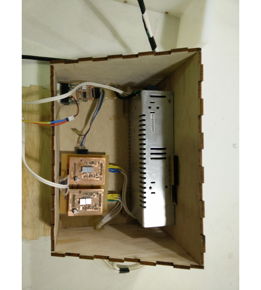
Custom electronics: I redesigned the stepper motor driver, FTDI USB virtual serial to USART connection board, and control board for two stepper motor driver shields. (Shields were designed by Gabriela from my design.) Power switch and power LED were added to the casing. Having a FTDI's chip in the control box is also very convenient for it needs only to be connected with a regular USB-cable instead of a special serial cable.
What materials and components were used?
The frame of the CNC-machine is made of 12 mm HDPE. The cross section and some other parts are printed of PLA. Mechanical parts include two Nema17 motors, 8 mm guides and lead screws, aluminium motor coupler, linear bearings and radial ballbearings. The sticker is vinyl. The power source is a chopper transformer capable of 13.5 V and 14.9 A. The control box is 4 mm plywood. The most essential electronic components are the FTDI's chip, Atmega328p and Allegro a3967 stepper motor drivers. There is also a bunch of wires, screws, nuts, bolts, resistors, capacitors and 16 MHz resonator. PCBs are FR1.
Where did they come from?
Other than stepper motors, motor couplers, threaded rods, smooth guide rods, and bearings bought from BCN Dynamics, everything was found in the lab. Minor resistors and capacitors are in the Fab inventory list, everything else was recycled left overs I was allowed to use.
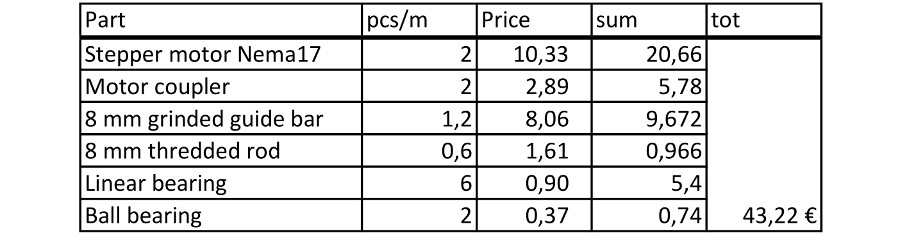
How much did they cost?
The mechanical components bought for the machine are:
The electrical parts are:
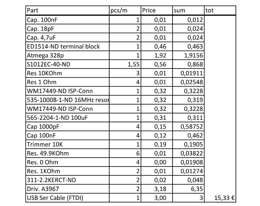
Rest of the materials were recycled or left overs I was allowed to use. I evaluate HDPE around 30€, power 20€ and other small supplies 30€. (Wires, 3D-printing, screws, etc.)Doing all together in total 138.55€. I calculated BOM with USB to Serial cable despite of the fact I made another version of it. We also found a spool of EDM wire less than 90€. That means the whole EDM machine would be around 250€!
What parts and systems were made?
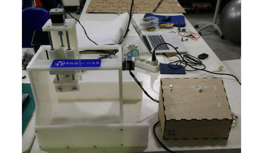
The result is a fully functional CNC-machine. The workflow from SolidWorks drawing to CNC cut object was tested. Parts made in this work include:
- Custom frame to support two axis, Y-axis parts and vise of HDPE
- Crossection supporting linear bearings and nuts for the lead screws of PLA
- Parts for motor holder and control box of PLA
- Sticker on the frame of vinyl
- Plywood control box
- Custom electronics
- Wire holder for the hot wire
What processes were used?
Processes used were:
- Large milling machine
- 3D-printer
- Sign cutter
- Laser cutter
- Precision milling machine for PCBs
- Electronics and embedded programming tool chain
Including no less than all the core processes.
What questions were answered?
I found answers for how to make mechanical parts with Fab lab equipment. I am also now familiar with the firmware and functionality of the software stack to use the machine. Tooling paths can be made with Fab Modules. I know now how to make a CNC-machine and use it. The work also covered the use of all essential Fab lab machinery.
There was no time or need, to continue to prototype the EDM parts. However there was time to learn what would be needed and how would they roughly work. Basically, EDM would require a power supply with added parallel capacitance for the sparks if necessary, spool holders, wire, wire holders, a motor and a brake for the spools, electronics and gears for the motor, the motor holder is already drawn and an aquarium pump with purified water to flush the cut.
How was it evaluated?
I evaluated the machine by making a test cut with the hot wire. The whole working flow and system was tested. I also run a demo presenting the machine.
What are the implications?
Considering the change of the schedule of Fab Academy and the fact that I couldn't extend my stay in the country for the second set of presentations, there was absolutely no room for errors in mechanical design. I haven't done any mechanical design earlier. I would have counted a success, if I had something that looks like a machine presenting the skills required to make such parts and if I knew what I did wrong. However, everything fit at its place, the machine was assembled and after a couple of calibrations everything worked and the cut object correlated with the drawing with good accuracy. This can only be counted as a total success!