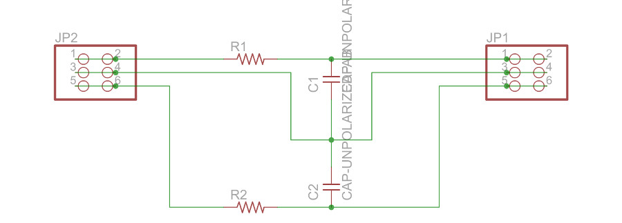
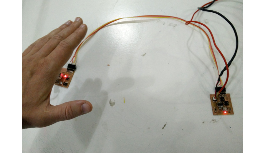
Week 13. Networking. I took the board designed for synchronous detection, changed the code to calculate difference of accumulated values of "off" and "on" stages and send the value to UART if there is a detection or not. The filter used in python code to show detection is removed and no hysteresis is added. Also calibration is rude, just the first value coming into my mind. Then I took the modified "Hello echo" board and programmed it to set LED on detection and shut it if there is no detection. I changed the "Bit delay" to match 9600 baud also in this code, so I have two boards communicating over the serial connection. I was able to get detection over 70 cm away. It's too much fun to play with! Making these little boards and connecting them over serial you can have lots of different set ups to test while fast prototyping.
There is some weird stuff in the serial codes:
    // set clock divider to /1

    //

    CLKPR = (1 << CLKPCE);

    CLKPR = (0 << CLKPS3) | (0 << CLKPS2) | (0 << CLKPS1) | (0 << CLKPS0);
The first line of the code sets the bit "CLKPCE" on and writes all other "0" (Datasheet says: 1. Write the Clock Prescaler Change Enable (CLKPCE) bit to one and all other bits in CLKPR to zero.) The second line on the other hand: (0 << CLKPS3) equals 0. If you take eight bit value of 0 (00000000) and then value 0 and shift it CLKPS3 times to the left it's still 0. It also doesn't matter how many of those are binary OR'd, result is still "0". (Datasheet says: 2. Within four cycles, write the desired value to CLKPS while writing a zero to CLKPCE.) So in the end the code works, but it has a lot of unnecessary shifting with zero. All avoidable with reasonable commenting.
This example is even better: if *rxbyte value was set 0 before this loop, all shifting with zeros could be left out. Shifting zeros is unnecessary, it takes memory space and processing time in the code. In general it should not be necessary shift zeroes!
//
   // unrolled loop to read data bits

   //

   if pin_test(*pins,pin

      *rxbyte |= (1 << 0);

   else

      *rxbyte |= (0 << 0);

   bit_delay();

   if pin_test(*pins,pin)

      *rxbyte |= (1 << 1);

   else

      *rxbyte |= (0 << 1);

   bit_delay();

   if pin_test(*pins,pin)

      *rxbyte |= (1 << 2);

   else

      *rxbyte |= (0 << 2);

   bit_delay();

   if pin_test(*pins,pin)

      *rxbyte |= (1 << 3);

   else

      *rxbyte |= (0 << 3);

   bit_delay();

   if pin_test(*pins,pin)

      *rxbyte |= (1 << 4);

   else

      *rxbyte |= (0 << 4);

   bit_delay();

   if pin_test(*pins,pin)

      *rxbyte |= (1 << 5);

   else

      *rxbyte |= (0 << 5);

   bit_delay();

   if pin_test(*pins,pin)

      *rxbyte |= (1 << 6);

   else

      *rxbyte |= (0 << 6);

   bit_delay();

   if pin_test(*pins,pin)

      *rxbyte |= (1 << 7);

   else

      *rxbyte |= (0 << 7);

   //

   // wait for stop bit

   //
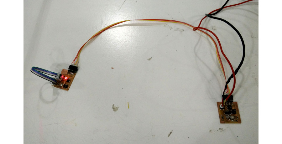
We found some capacitors with unknown values. I drew a low pass filter to test them. I checked with oscilloscope on which frequency the amplitude was half of the maximum and simulated the situation with LT-Spice until -3 dB pole was found as well as the capacitor value since the resistor was known. Later I found out there was a multimeter in the office capable of measuring capacitance. Both measurements gave the same value.