
Networking and Communications
Serial Communication
I chose to focus on Asynchronous communication- RS-232.
Serial commuication works using two pins called TX and RX, for Transmiting and Receiving data.
It consists of :
- A bridge board- this board bridges between the computer and the other boards
- Multiple Nodes- as many nodes as you want, doing whatever you want!
Generally programming the boards directly in C is 10 times faster than using the Arduino IDE (due to all Arduino's libraries). However as I am a novice to the system I will learn the basic concept using the Arduino IDE.
I made the boards on this page under serial communication. I downloaded the hello.bus.45.c and makefile into a new folder. Then in my Linux terminal I access the folder where I downloaded the code files.
I followed
this tutorial for programming the boards.
First I programmed the Bridge board as node #"0" with my FabISP, and FTDI cable for power:
sudo make -f hello.bus.45.make program-usbtiny
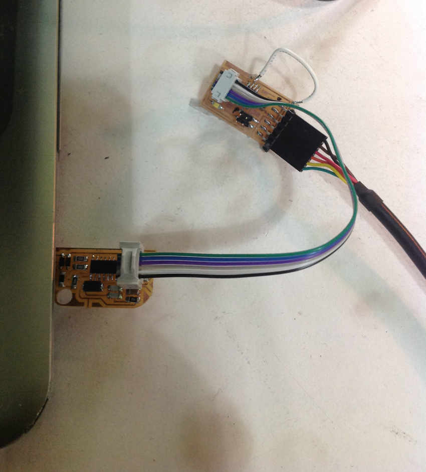
 Then I programmed the node board, connecting it to the bridge board for power via the 4 pin header, and moving the rainbow cable from the FabISP.
However this time I opened up the c file and changed the node #"1" Again I execute:
sudo make -f hello.bus.45.make program-usbtiny
I repeat this process for the second node board, naming it node #2.

Then I open the Arduino IDE from terminal
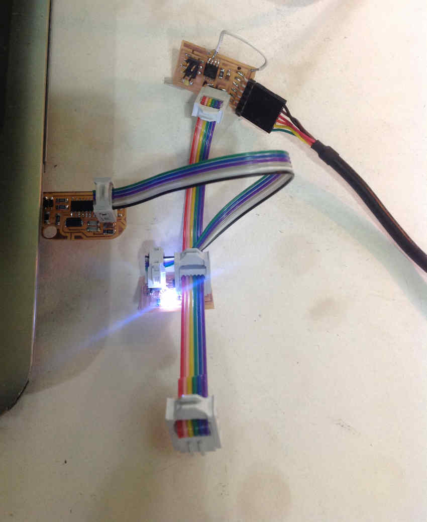
sudo arduino. I go to Tools, Serial Monitor. I simple type the number of the node I want to flash, and click send. All node leds flash once and then only the node typed flashes another time.
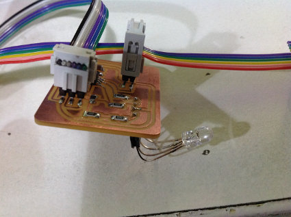
I had some extra time so I wanted to create a RGB LED node board to serial communicate with the bridge board from Neil's class. First I had to find the data sheet of the LED. Here I was able to identify that it is a common cathode LED (opposed to a common anode LED- which we have used in previous RGB LED examples in the fab lab).
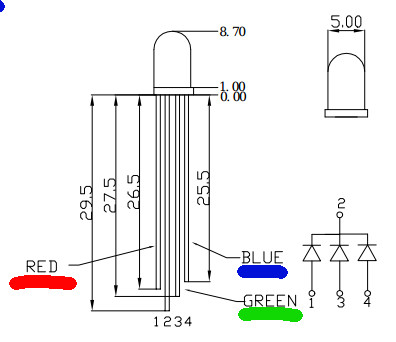
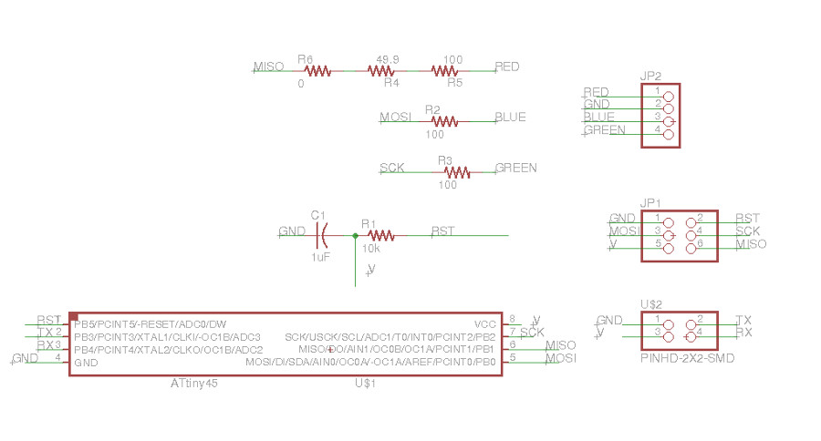
The cathode gets connected to ground- and power to the R G and B leds will be generated from the following ATtiny 45 pins:
| LED colour | Pins |
| Red | PB1 / MISO |
| Blue | PB0 / MOSI |
| Green | PB2 / SCK |
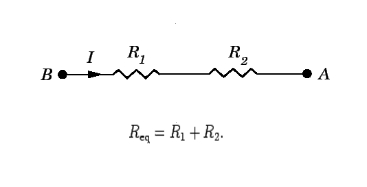
Before I make my board I calculate the resistors necessary for the RGB LED. Green and Blue have the same specs, but the Red LED, requires a higher resistance:
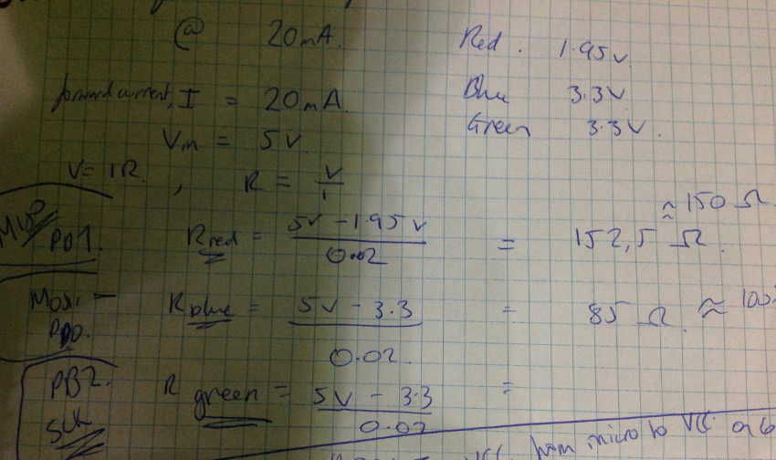 Since we didn't have any 150 ohm resistors I used two resistors in parallel.
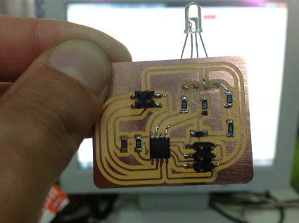
For node #"2" , unfortunately I was not able to program the board and I realised my mistake of connecting all RGB pins to VCC, which is not necessary. 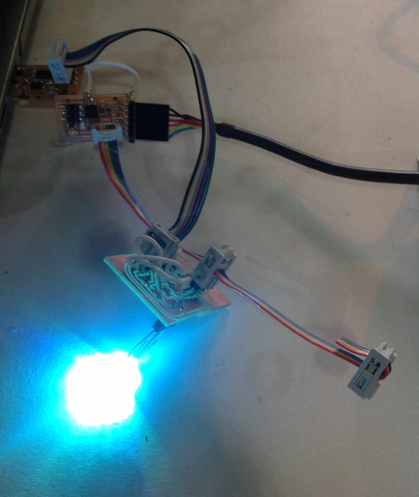
In programming instead of lighting each LED colour by draining the current from the relevant pin, I will give a high voltage to the corresponding pin for the relevant colour.
So back to the schematic!
The final set-up... and it programmed successfully!
However I ran out of time to get it to function correctly. It stays lit since it is a common cathode LED. I change the set and clear functions around in C so it switches off instead of switching on from off, that is as far as I got.
Get my files for the RGB common cathode node here