Computer-Controlled Machining
Part One Callibrating the CNC milling Machine
Part Two Designing my Something Big
Part Three Day One of Milling
Part Four Day Two of Milling
Part Five Troubleshooting when a CNC isn't Milling properly
Part Six The files
Callibrating the CNC milling machine
The machine I am using uses DC motors with stepper encoders for XYZ to generate the steps. So instead of sending steps to the motors, you send the coordinates.
The machine speaks G-code!
G-code though universal can vary with machine. G-code conversions can be made in RhinoCam plug-in for Rhino and Inkscape.
I decided I wanted to learn the commands that can be sent to the machine.
Example
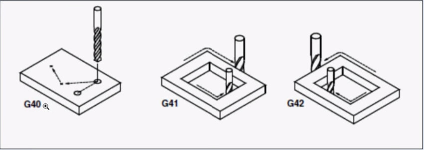
G41 drills outside the line CW and inside the line CCW
G42 drills inside the line CW and outside the line CCW
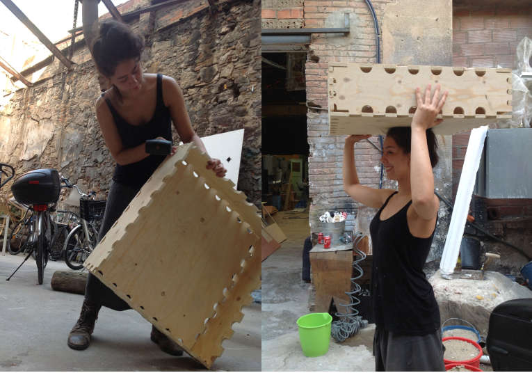
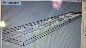
Designing Something Big
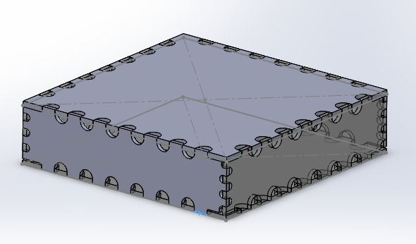
I will make a box to fit my final project into. I don't like dogbones so I made curves for the drill bit to follow instead. The curves had to have a diameter bigger than my drillbit. I chose a drillbit of 6mm.
I really wanted to figure out how to use Solidworks parametrically, here's how I did it:
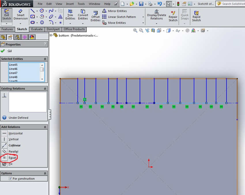
1. Draw all the lines you want to change separately, i.e. instead of making boxes I made separate lines. Then I made all the bottom lines equal:
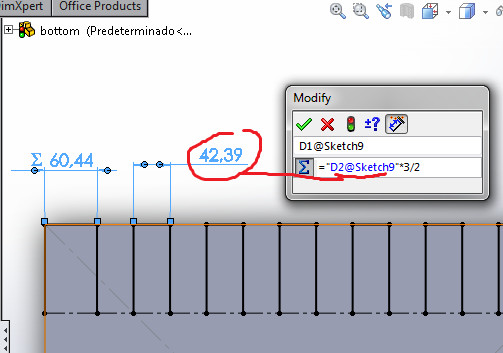
2. Using Smart Dimension, I create one side an equation of the other. Solidworks does the math so I don't have to!
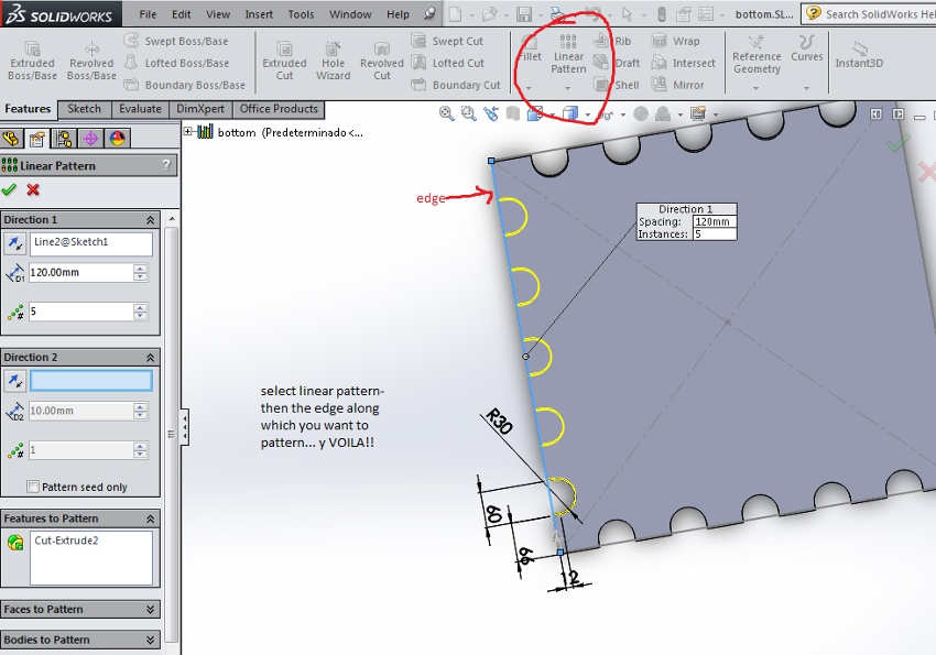
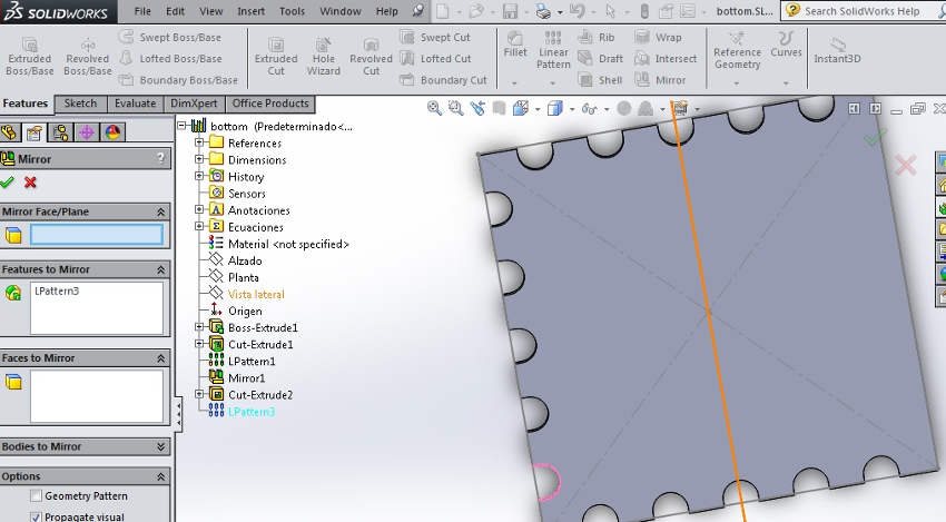
I make a linear pattern by selected the Feature to be extruded and then using the Linear Patter funciont. Then I mirror them over to the other side.
I particularly enjoy creating an assembly as I struggle with imagining how the corner sides will meet.
I make test pieces to try out the joint. I am following Neil's advice to make one joint fit first before making the whole assembly. I have one control piece to test with another piece of changing sizes with increments of 0.2 mm.
Export from Rhino as a dxf and imported to Rhino Cam for the milling settings.
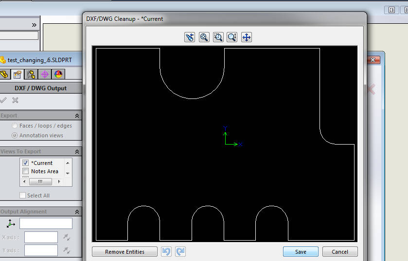
Once imported in Rhinocam I:
- "Join" the lines in each test piece so that I can move them around easily and I ensure their separation is larger than the tool width, i.e. larger than 6mm
- Create a stock material, a rectangle which is then extruded to the same depth as the piece of wood I will be milling. In Rhino Cam I select Stock from selection and select the cuboid.
- Make sure the XY orientation is coherent with the machines XY in relation to your wooden piece.
- Delete the stock cuboid.
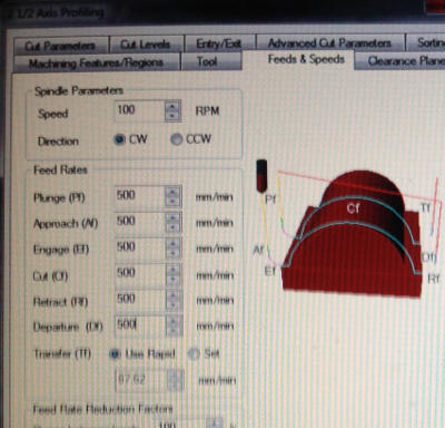
- Adjust the settings in Rhino Cam, I select the Feed Speed to be 500
- I post the files and select MACH3 as the machine I will be using.
Making tabs using Rhino Cam
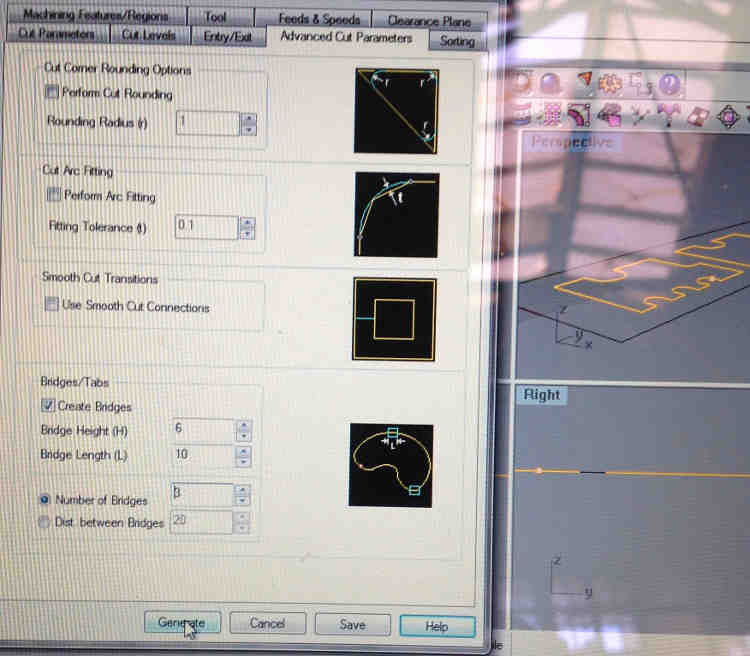
CNC milling is all about getting the right balance between the feed speed and spindle speed.
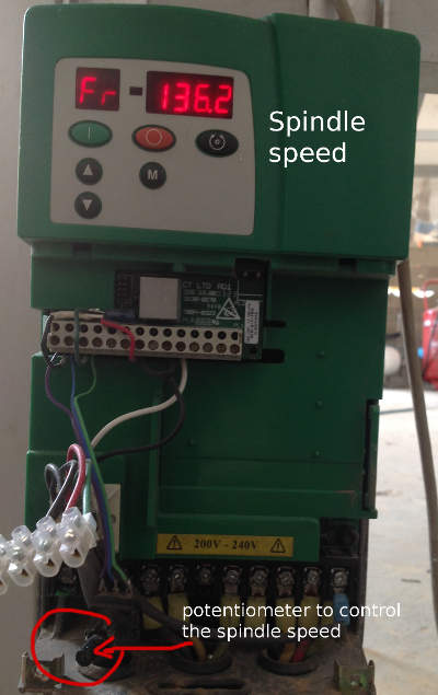
My spindle speed settings, this was a hack they had made at the Fab Lab Barcelona. We use a potentiometer to change the speed of the spindle:
Day One of Milling
I had forgotten I need to fix the wood down on the sacrificial board. first, so before milling I did it the manual way. Next time I will remember the holes for fixing the board in place.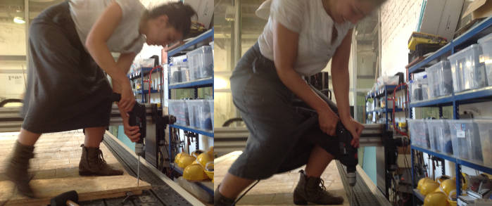
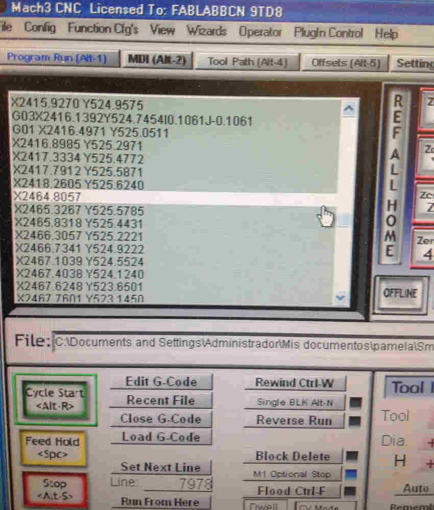
The Mach3 keeps crashing mid mill. After the XY zero is set and the gcode loaded, it will stop mid milling. I ask other fabbers, they have had the same problem, some will save their last position and then reboot and start from that line of gcode. However after trying this I encounter another problem. Suddenly the Z zero is lower than my stock material.
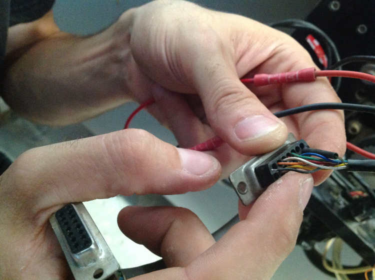
Thankfully Ferdi is on hand. He decides to take a good look at what is going on...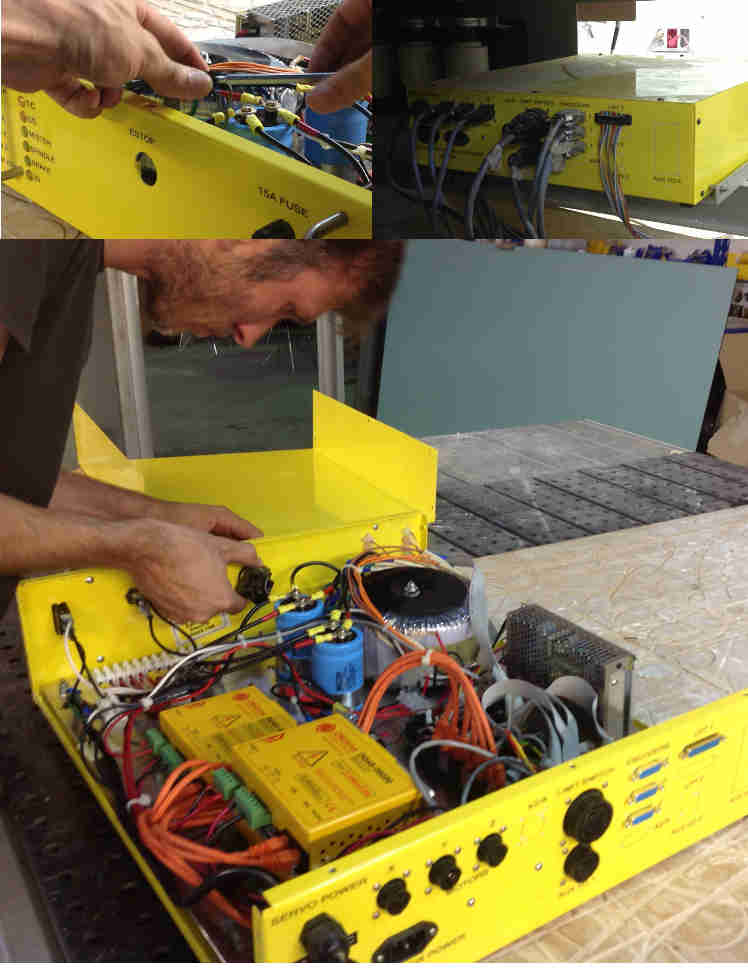
Ferdi finds a cable coming loose where the button is. He fixes it and adds two screws to make sure it stops moving about. After reconnecting everything we restart the gcode- so far so good, no crashes!
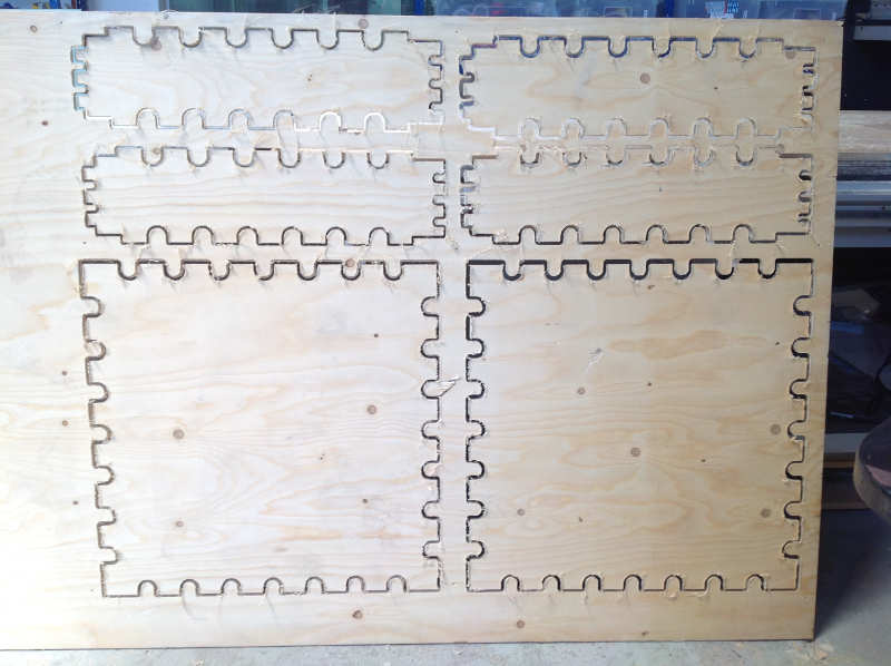
The test pieces, I decide that the pieces only need an offset of 0.2mm to fit nice and snug:
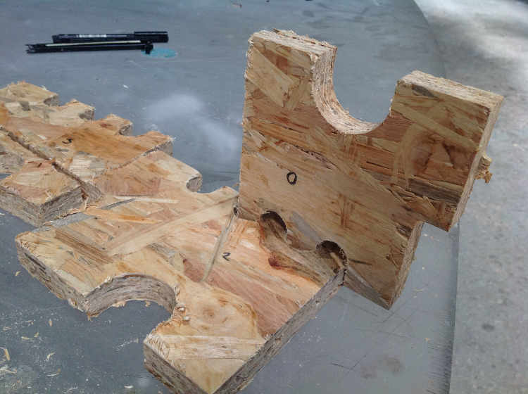
Day two of Milling
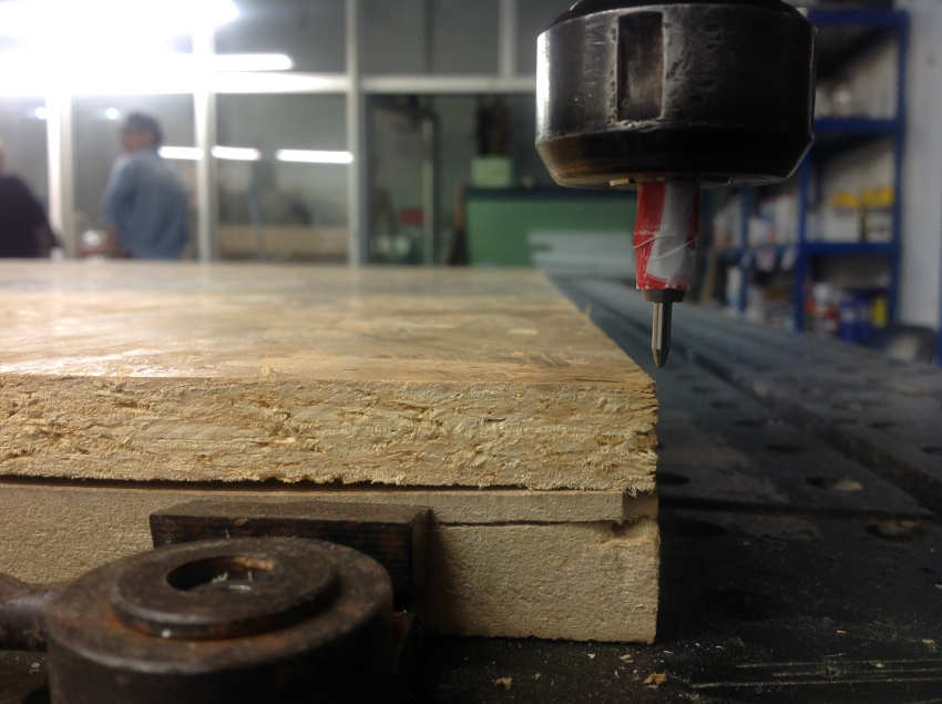
This time I remember the holes to fix the my wood into place. I used 3mm drill for the holes to fix the wood into place. Then changed the bit to 6mm for the profiling.
I am using Fir Spruce WISA Plywood board WBP with 12mm depth for this piece.
More problems- crashing still. The machine has lost steps:
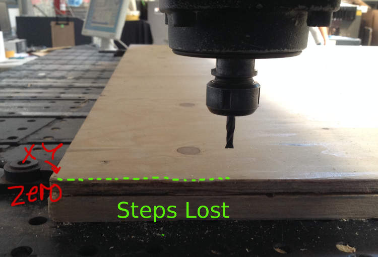
How Ferdi located the problem:
After Ferdi fixes the cable I manage to get through half the pieces without it crashing. Then taking the original file, and re-made it so I do not have to mill all the pieces again. I switched off the machine and checked the cable, it was looking loose so I jammed it in more. Started the machine again and sent the new gcode. So far so good.
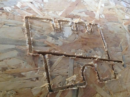
But, I start to look at the pieces and something isnt right. The holes aren't big enough and the joints aren't small enough. I start troubleshooting with Ferdi, all the measurements are wrong, e.g. a 42mm side is 48mm.
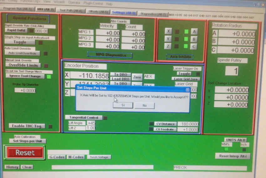
Troubleshooting when the CNC isn't cutting correctly
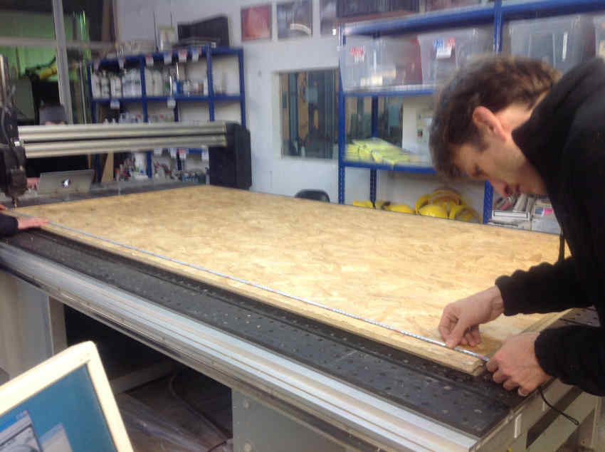
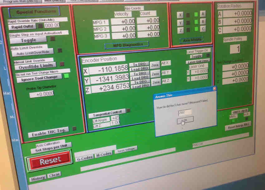
- Check the machine's steps are correct i.e. move it 1m, and measure what the machine moves with a measuring tape
- Check your design
- Check the milling setting you made, in my case I used RhinoCAM e.g. did you ask the machine to mill inside or outside the line?
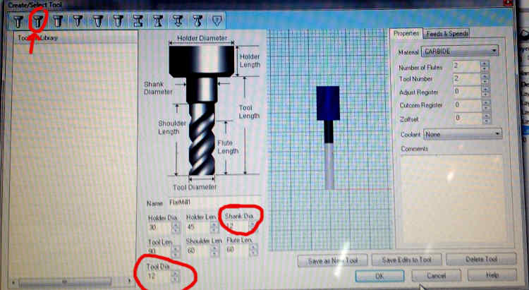
- Check you selected the right drill bit. This was my shortcoming. The tool selected was 12mm instead of 6mm! How? Well although I had written 6mm in the tool diameter box, after selecting the flat head tool, it changed the diameter automatically! So always check and double check your settings.
Speed settings:
I change the Rhino Cam settings to have the 6mm bit and mill over what has already been done. Since all the pieces are too large, I can try and salvage the pieces to be usable.
After some sanding, sawing off of the tabs and knocking together... I have a nice sturdy box....finally!!