COMPUTER-CONTROLED CUTTING
PROTOTYPE
We have to design, make and document a press fit construction kit. I decided to do something related to the geometry of my final project: a sphere. To do this I started thinking about Füller domes and how they were constructed.
PROCESS
This has been my process:
1. Draw in Autocad a sphere surface.
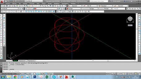
2. Import it in 3D Max to export in .obj archive.
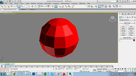
3. Import it in 123D-MAKE
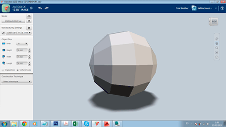
4. Play with different options and choose one.
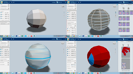
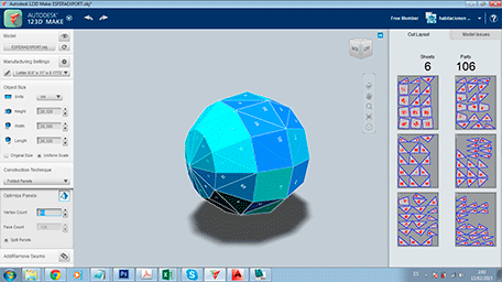
5. Put the adequate joints and export the blue prints.
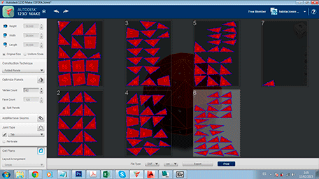
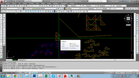
6. Edit then in Autocad.
7. In that moment I started thinking about doing a lamp. The geometry is perfect.
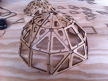
8. So I re-designed all the pieces, putting a hole inside of each one, all in Autocad.I have been very careful whith the joints. I respected the center of each one and only I have make changes in the width of each one. I looked for a very simple joint that could adjust to different angles.
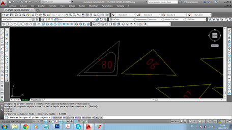
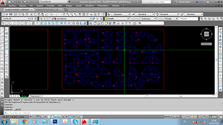
*I have had a lot of problems importing from 123D-MAKE to Autocad. The numbers were a crazy group of lines in the XYZ space. Flatten and Geoplana commands didn´t work.Finally a could fix the problem converting this lines in surfase and then in solids. The las I dis is execute geoplana command. This time it worked out.
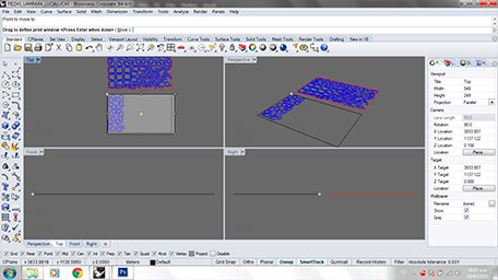
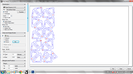
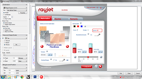
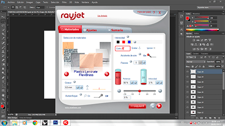
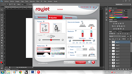
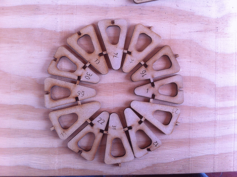
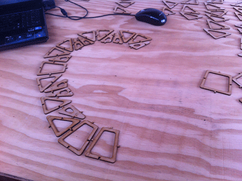
9. I imported the Autocad .dxf file to Rhino to print it in MDF whith Trotec Rayjet laser cutting machine.You can see in the images the adjusments.
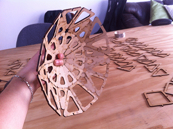
10. Once I had all the pieces of the lamp I assembled them, you can see here what it was:
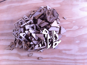
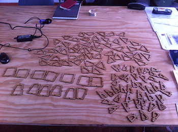
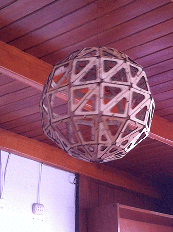
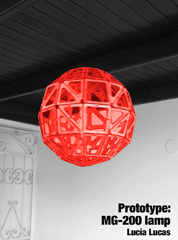
* I have to say that 123D-MAKE is a very good program, but is no perfect. I have had one human error,but I have had problems with 4 pieces because they where wrong in 123D-MAKE blueprints. These problems were: - The pieces were not well numbered. - The joints weren´t correct. - The position of the piece was wrong.
This is a video of the process:
And here is a video about the final result of the prototype: