


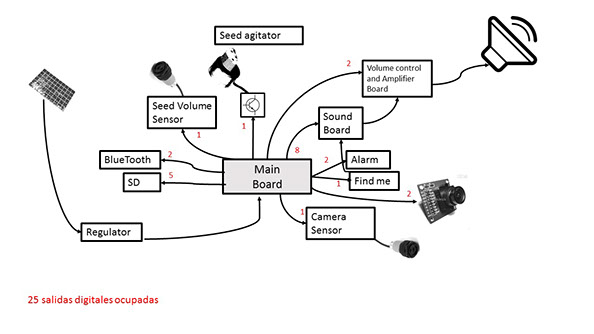
Final project diagram
In this assignment I decided to start with my final project.
The project is a bird feeder that take pictures of birds feeding and has a sound system with different bird sounds to attract species.
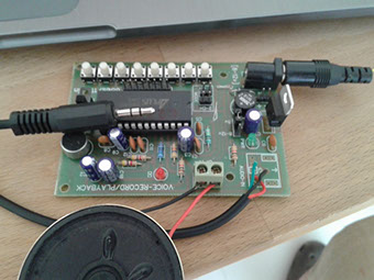
I will use an off the shelve board that reproduces sounds and I made an amplifier with a digital potentiometer to control volume, since the same board will control bird sounds, alarm and find me function.
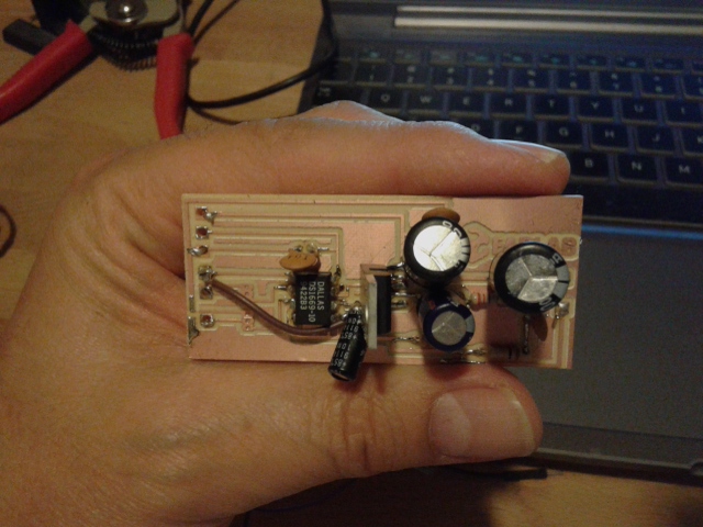
I found this two circuits (http://pablin.com.ar/) and put them together in a single board
+
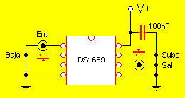
Digital Volume control
=
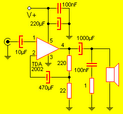
8W amplification
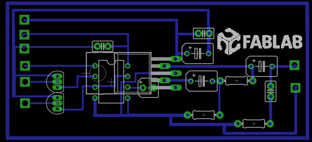
You can find the link to the Eagle design by clicking here
Parts needed to build the digital Volume control with the 8 W amp>
Digital potentiometer DS1669
100 nF Capacitors: 3 pz
TDA 2002 circuit
220 microF Capacitor
1000 microF Capacitor
470 microF Capacitor
1 ohm resistance
22 ohm resistance
220 ohm resistance
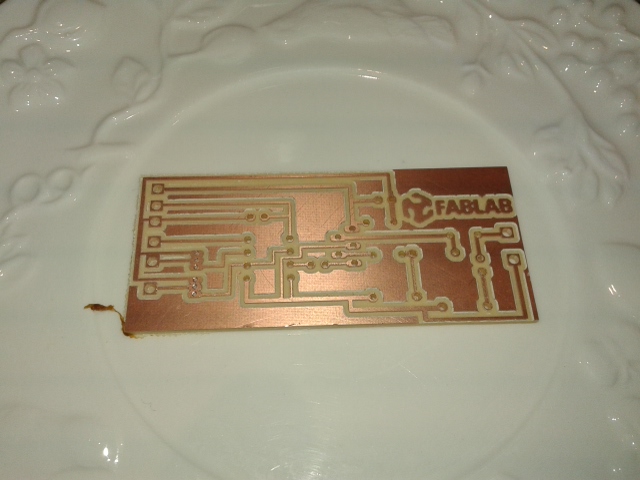
At first I was using two transistor to control volume up and down, at the end I did not use them since I can could control the board directly with the Main board.
The final result with this circuit was that the volume control did not work, we think is the digital potentiometer is damaged.
Later I Used only the amplification part of the circuit, that is why you see a jumber cable in the middle of the board. It turned out to be too noisy so at the end I am not using it in my final project.
Ouch!
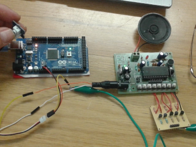
To make the bird attracting system, I am reusing a board I got on a FAB 10 workshop. This board is capable of reproduce 8 different prerecorded sounds. The original idea was to have 6 bird sounds + Alarm sound + Find me sound.
Once I had the circuit the next step was to record bird calls.
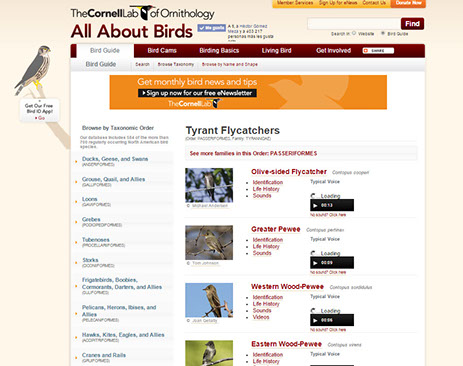
I got this bird sounds from the Cornell lab of ornitology web page. This is probably the best bird information repository in the world, according to some biologists.
To make the bird attracting system, I am reusing a board I got on a FAB 10 workshop. This board is capable of reproduce 8 different prerecorded sounds. The original idea was to have 6 bird sounds + Alarm sound + Find me sound.
Once I had the circuit the next step was to record bird calls.
I got this bird sounds from the Cornell lab of ornitology web page. This is probably the best bird information repository in the world, according to some biologists.
Another pcb needed for my final project, due to Sound board architecture, is a board that can control bird songs on and off . Since the sound board needs fiscally to push a button, I decided to use transistors and bypass the buttons on the sound board in order to play different songs with an order from my main board previously programmed. You can find the eagle file of this board by clicking HERE and the png file clicking HERE.
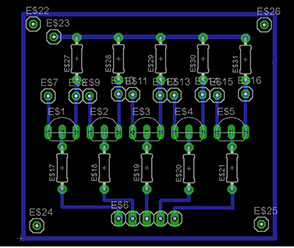
In order to assure the boards proper functioning I used a 5 V positive signal with a 75K resistor.
The board works really well, I am very happy with the result.
I made several testing with the amplifier board I made but it is too noisy, and the digital potentiometer did not work properly.
Another consideration is that in my final project I am going to reduce from 24 to 14 input /outputs so I can use a smaller board.
I will eliminate the alarm and the "find me" sounds, without these I don´t need the volume control any more and that reduces another 2 control outputs from my board.
The transistor board I designed to bypass the physical soundboard buttons works great, allowing the sound board to play with a 5V signal from my main board.