
SIXTH WEEK ASSIGNMENT
 |
 |
 |
 |
ELECTRONICS DESIGN
Redraw the echo hello-world board, add (at least) a button and LED (with current-limiting resistor) check the design rules, and make it.
extra credit: simulate its operation.
- This
week's assignment is to make the electronic card with a ATTINY44 and
The first thing to do is have the data from the microcontroller Tiny44
to know how it works, etc.
We planned to make two cards, one with a micropocesador, with its vital components that can be used to test other applications in the future, and a second card with the input and output components. In this case it has 4 buttons inputs and 3 led outputs. This should be enough to test small programs, before thinking about the actual application..
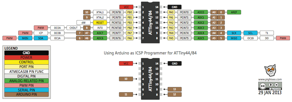
It is a subfamily of the AVR atmel: they are micro crontrollers, the pins can be reconfigured for use as I/O.
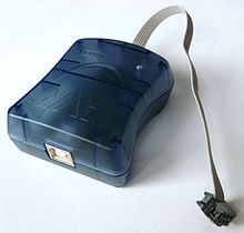
Atmel AVRISP programmer, and Fab.
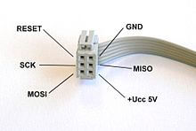
Pinout of the cable ISP / Sample ISP connector pins
The AVR is a family of RISC microcontrollers from Atmel American manufacturer. The AVR architecture was conceived by two students at the Norwegian Institute of Technology, and later refined and developed in Atmel Norway, a subsidiary of Atmel founded by the two architects of the chip. It has many fans because of its simple design and ease of programming. They can be divided into the following groups:
- ATxmega: powerful processors with 16-384 kB programmable flash memory ..
- ATmega: AVR microcontrollers great with 4-256 kB programmable flash memory ...
- ATTINY: small microcontrollers AVR with 0.5 to 8 kB of Flash programmable memory encapsulated 6-20 pins and a limited set peripherals
.


EAGLE
EAGLE, (stands for Easily Applicable Graphical Layout Editor) is a program for designing diagrams and PCBs auto router.
Famous around the world DiY electronic projects, because many versions of this program have a Freeware license and lots of component libraries around the net.
EAGLE editor contains electronic diagrams. Components can be placed in the diagram with a single click and easily routable with other components based on "wire" or "labels".
Eagle comes with component libraries included, easy to make and available from companies such as SparkFun or fans that spread around the net for free.
The ULPs are a type of scripts written in a computer language like C programming you are able to add custom EAGLE, such as opening and saving files to the program unknown functions.
On the net you can find support forums and tutorials fit to start using EAGLE. Learning is facilitated thanks to the intuitive graphical interface.
Command toolbar of the Schematic Editor (left)
and the Layout Editor (right)
and the Layout Editor (right)
This is the diagram of circiuit of the processor the main components can be seen including:
The energy input through connector J1, The voltage regulator IC2, button to reset S1, voltage indicator LED,
the resonator Y1.
The files can be seen here

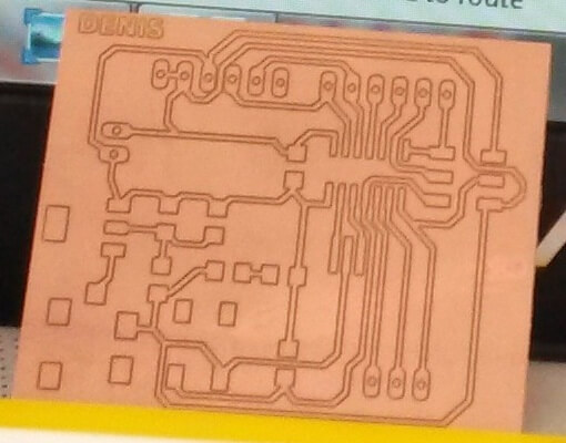
The picture corresponds to a manual routing.

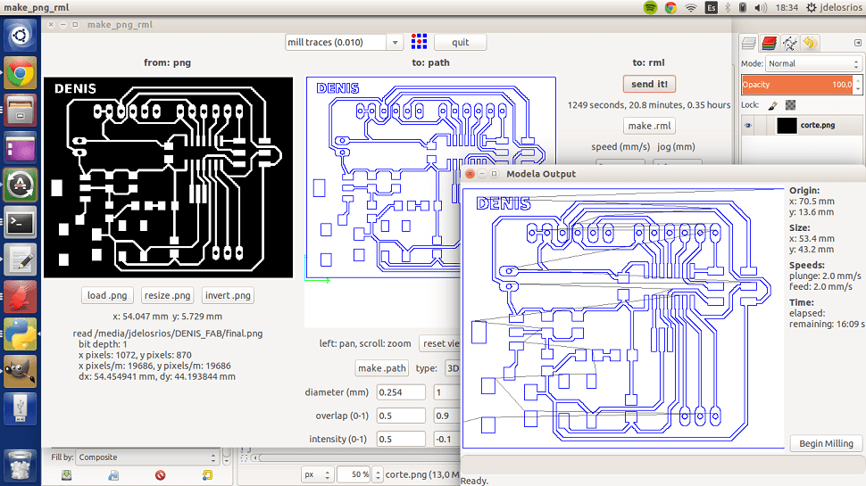
Here shown when working the MODELA.
After cutting, the next step was the welding of components.
Verified the first card.
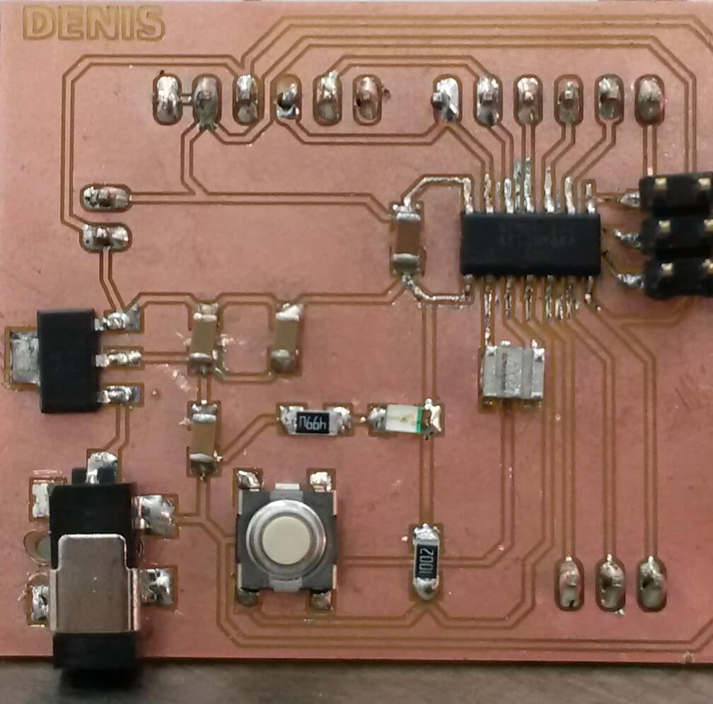

ROUTING MANUALY

It's always so hard welding small components
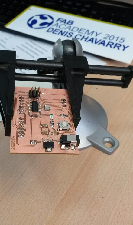

ASSIGNMENT COMPLETED
Task accomplished.
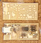
Finally, here the two cards manufactured shown and ready for the next stage of programming.
Finally, here the two cards manufactured shown and ready for the next stage of programming.

