

TENTH WEEK ASSIGNMENT
 |
 |
 |
 |
INPUT
DEVICES
- Measure something: add a sensor to a microcontroller board that you've designed and read it.
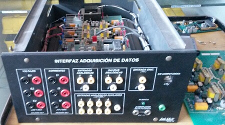
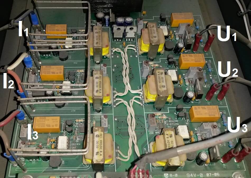
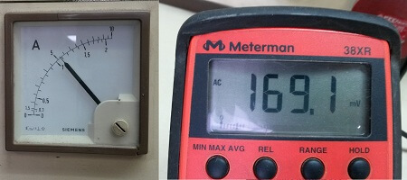
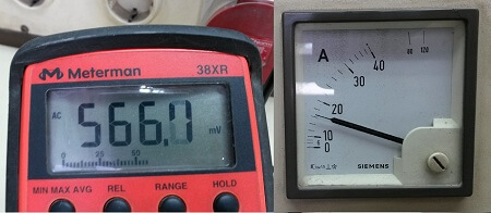
- We can see an interface of Lab Volt electrical, voltage and current signals.
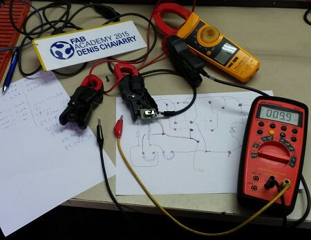
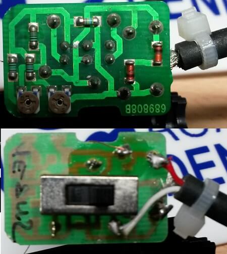
- A current clamp, and current sensor where I was able to test and confirm that I can use with our Atiny 45.
An current clamp sensor is tested to a current of 10A, confirming its linearity.
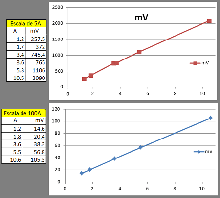
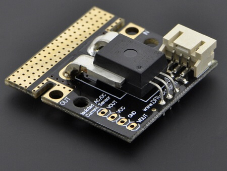
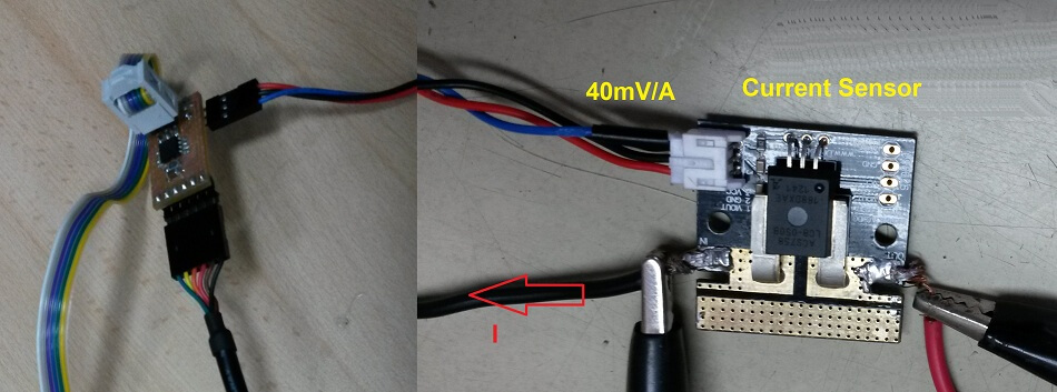
This is a breakout board for the fully integrated Hall Effect based linear ACS758 current sensor. The sensor gives precise current measurement for both AC and DC signals.
The current sensor outputs an analog voltage output signal that varies linearly with sensed current.
40 mV / A
This current sensor enables you to monitor currents in my project.
Specifications:
-Operating Voltage(analog): 5V
-Peak Measuring Voltage:3000V(AC),500V(DC)
-Current Measuring Rang:-50~50A
-Sensitivity:40 mV/A
-Operating Temperature: -40~150°C
-Dimension:34x34mm .
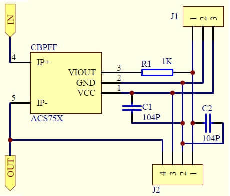
1. For this assignment, I decided to use a magnetic field sensor.
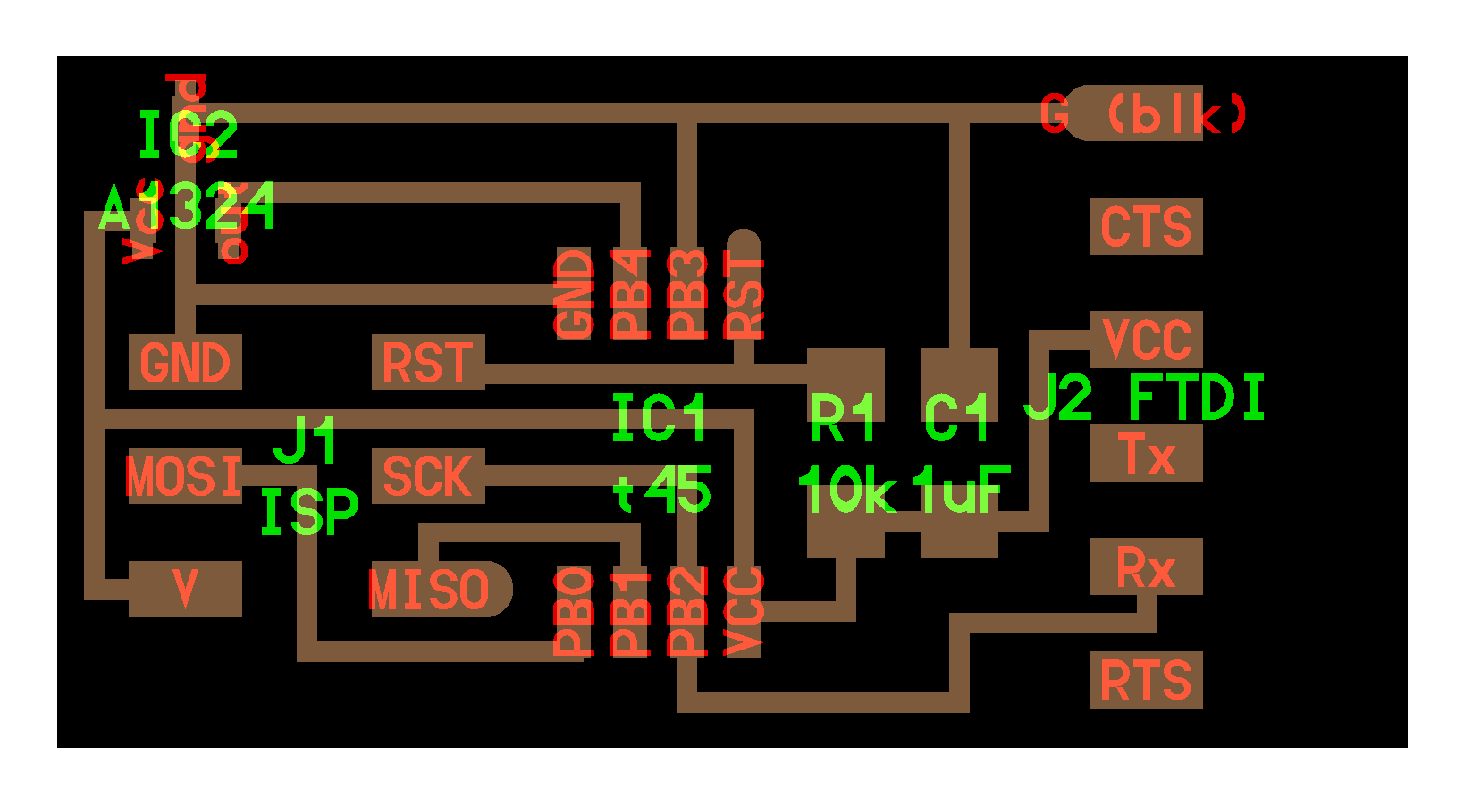
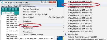
2. I decided to use ATtiny45 microcontroller, and connect a current sensor which delivers signal through analog input
to ATtiny45 microcontroller.
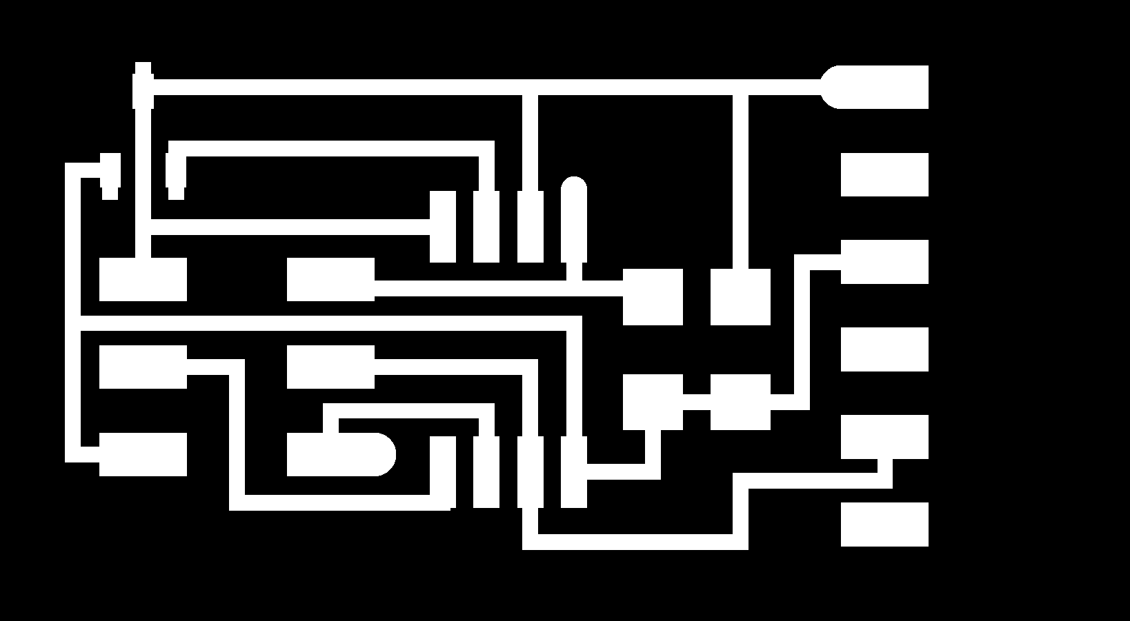
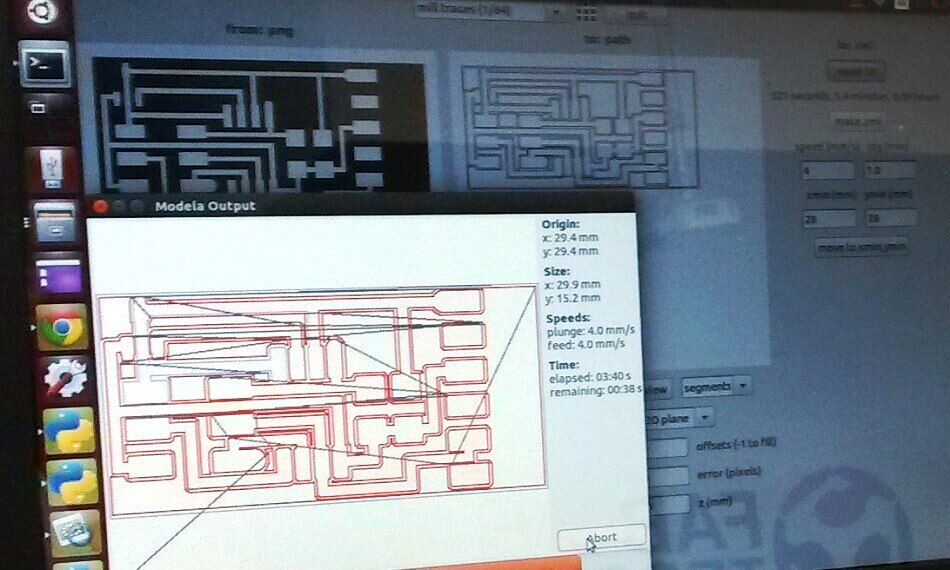
3. Downloaded the images in PNG format, for its use on the Modela.
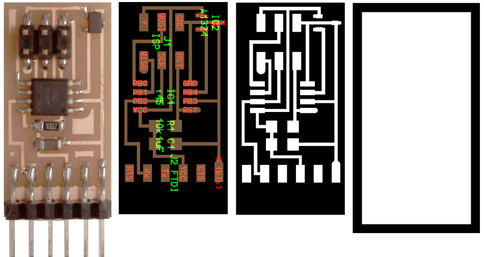
In the process of milling the card I used the MODELA machine with the configuration shown in the picture
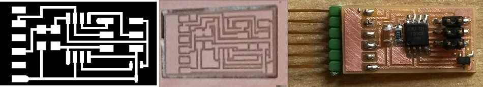
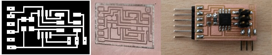
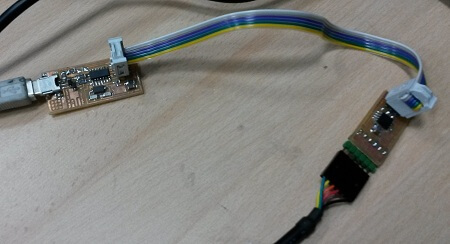
A card with the magnetic sensor and another one with terminals for connection of external sensor. Traces and interior.
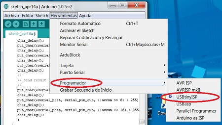
Connecting the ISP to the card and download the program. The program used is what gives the reference Fab documentation.
hello.mag.45.c
PYTHON
In the modified card (without magnetic sensor), I connected the current sensor and also could display the value on the PC.
This test is performed with laptop Fab because they had the Python program installed. Open a terminal and type these lines: Python hello.mag.45.py / dev/ttyUSB1
Files here: hello.mag.45.py
Some Conclusions?
- I have a lot to learn from this assignment.
- Be very careful with welds.
- Be careful with sofware, not all work the same