
ELEVENTH WEEK ASSIGNMENT
 |
 |
 |
 |
OUTPUT
DEVICES
- Add an output device to a microcontroller board you have designed and program it to do something.
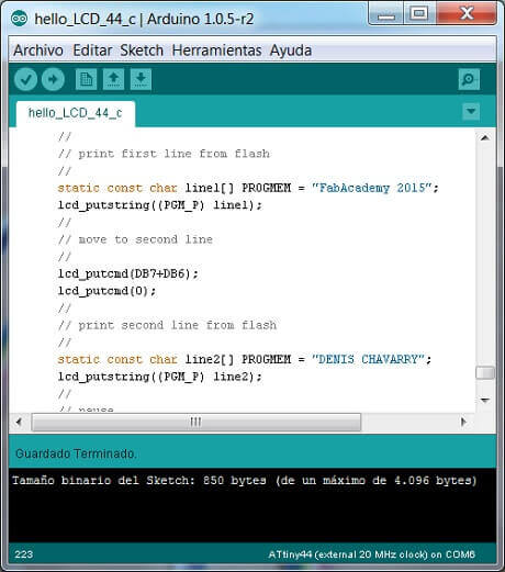
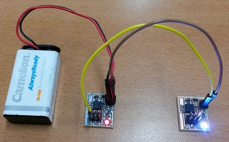
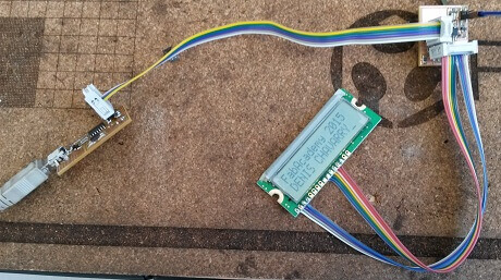
- Implement 2 FAb examples, the RGB LED and the LCD DISPLAY. Modify the program to achieve visible changes.
- Implement a sunlight sensor for a solar panel.
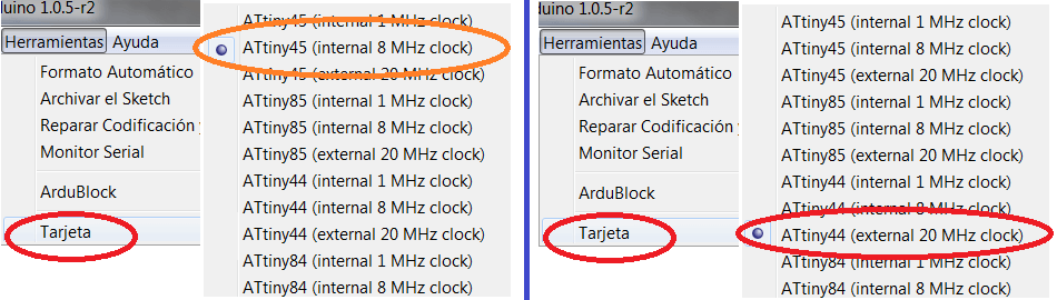
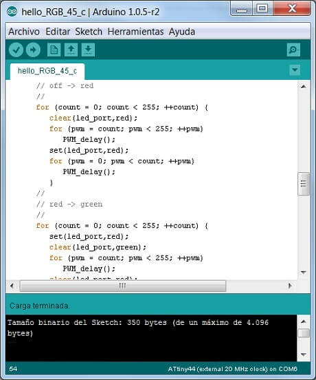
I decided to implement the RGB LED that is controlled by Attiny 45, and the DISPLAY LCD that is controlled by Attiny 44 to be able to understand the diagrams and the program code.The next step is to make some modifications to the program to achieve visible changes.
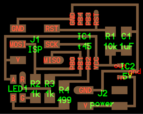
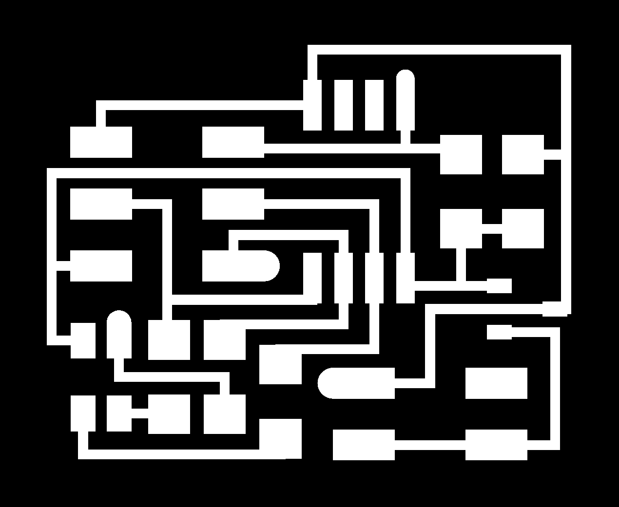
RGB LED
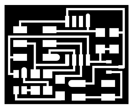
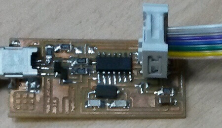
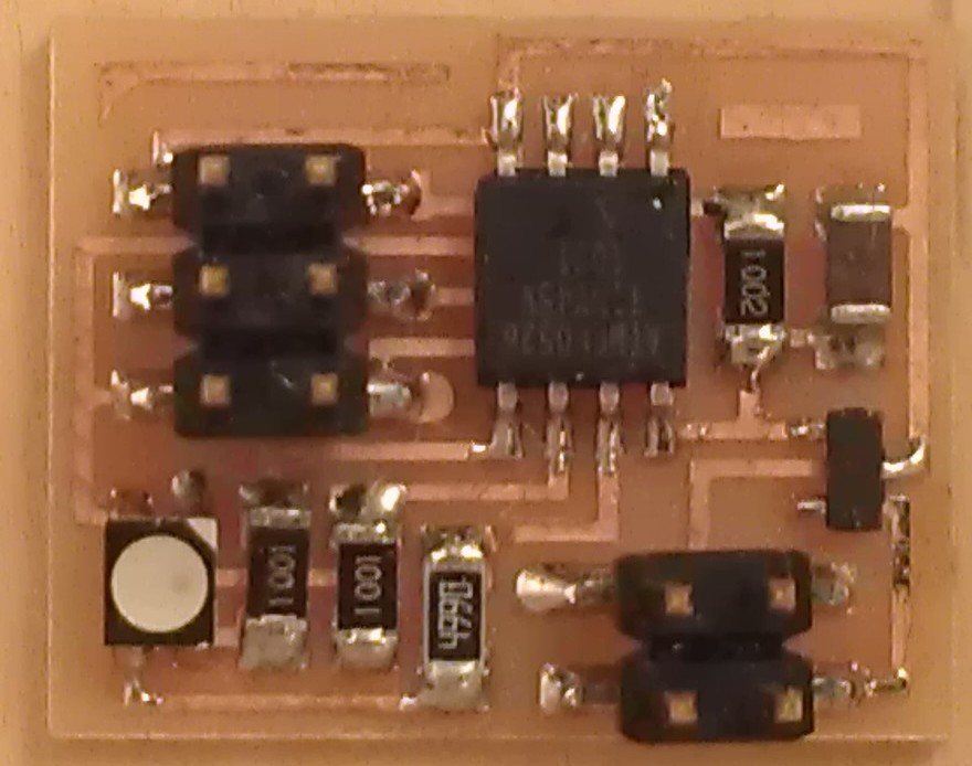
These are the assembling diagrams of circuit board. You can see that It doesn´t have a resonator, a voltage regulator, and ISP conection, and it uses 3 output to control the led.
 hello.RGB.45.cad board components
 traces interior C makefile video
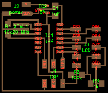
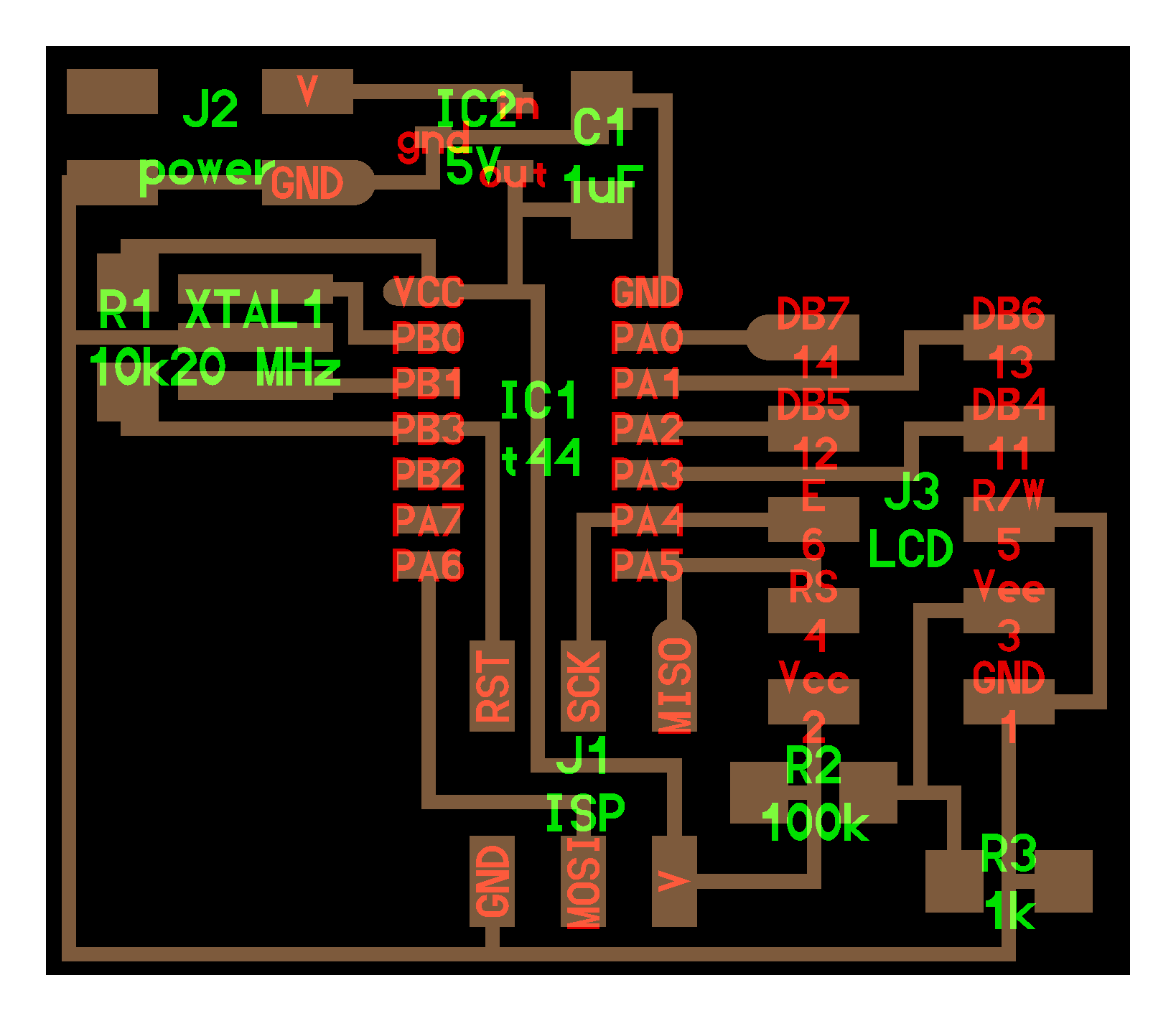
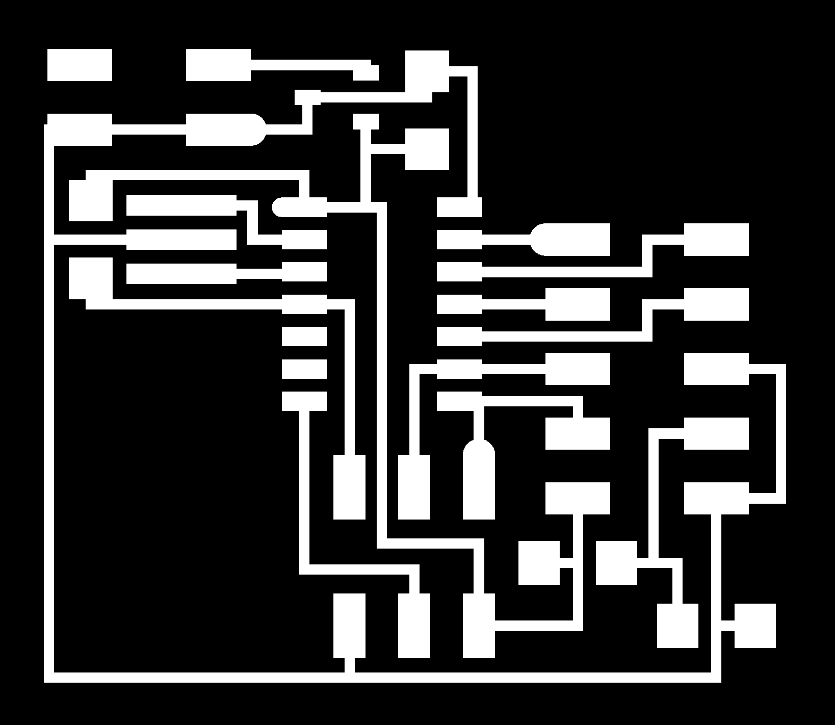
LCD DISPLAY
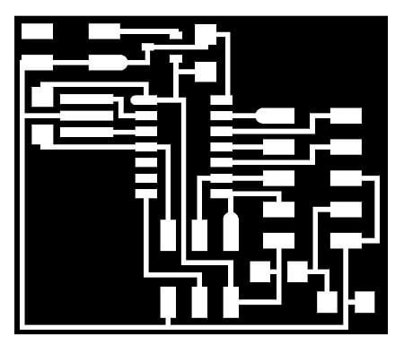
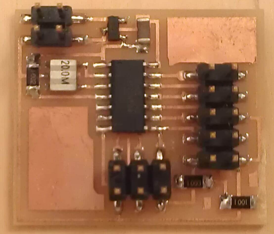
In this case the circuit has a 20MHz resonator, a voltage regulator, and ISP conection, the display must be conected to J3.
 hello.LCD.44.cad board components
traces interior C makefile video serial

.
Here the file
ASSIGNMENT COMPLETED!
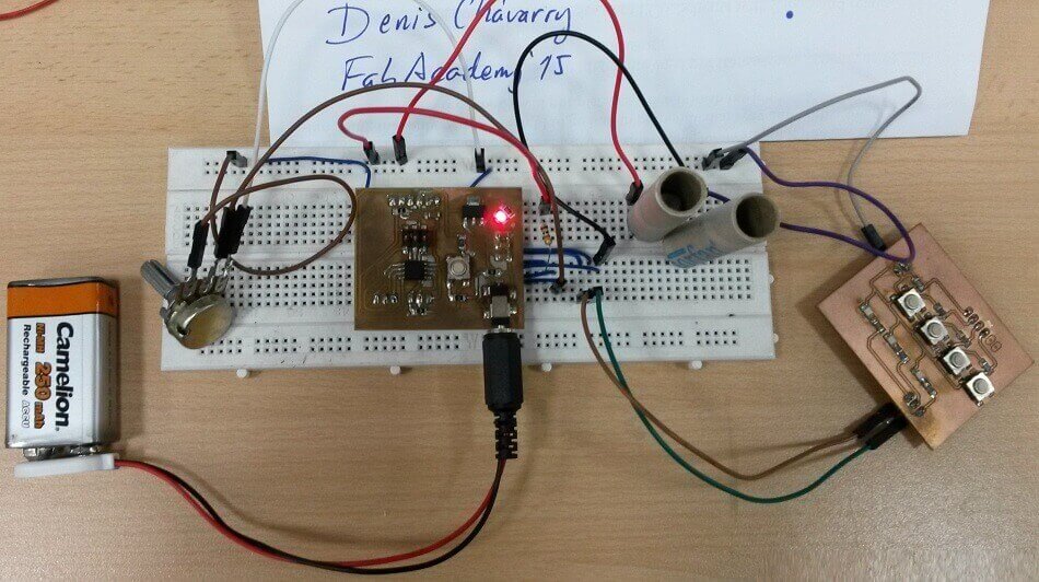
For this assignment we have a solar panel and I can control it on one AXIS.
So I need to implement a sunligth sensor with one axis with Attiny 45.
Online there are many applications about this topic.
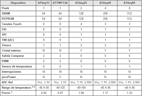
I found a particular website with Attiny 13 applications.
Have seen the Attiny 13 and 45 configurations, and the pin configurations are exactly the same, and the 45 has better performance.
Files here: sunlight sensor