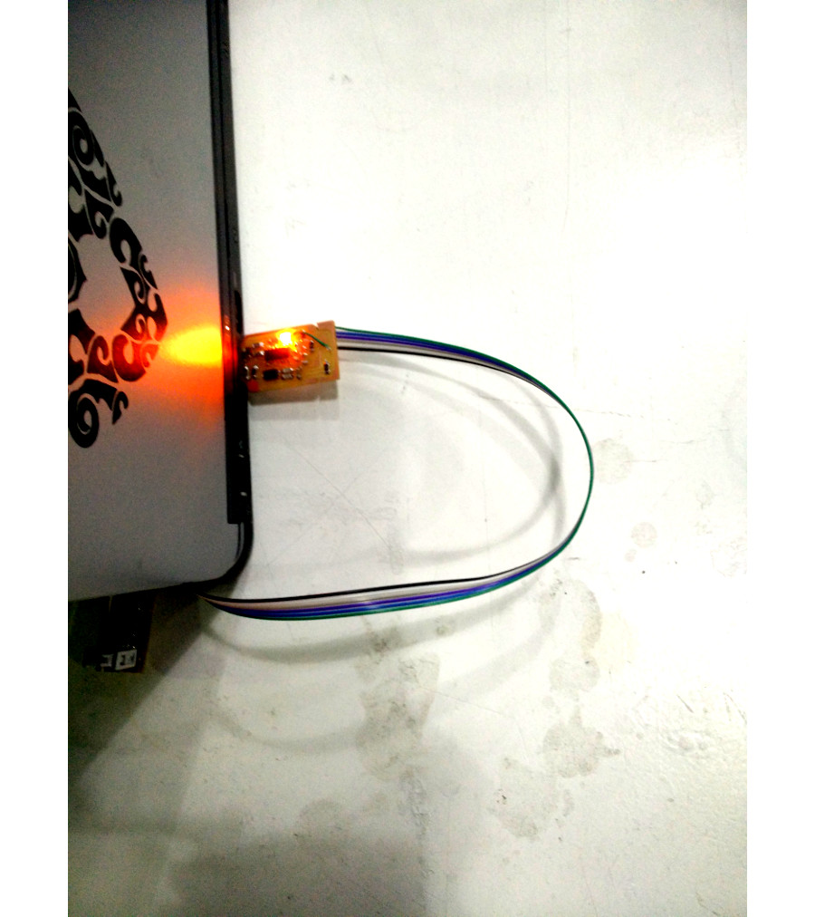
Week 4. Electronics production. The task of the week is to learn to use Roland's Modela MDX-20 for milling PCBs and solder and hopefully program FabISP programmer. I made my own design using Eagle. Basically, it's the same, except I added a status LED. I have often found it very useful. Its first function is to light up when the program in the programmer works. This is usually achieved by the bit masking the wanted leg of the microcontroller as output in data direction register and changing its status in output register at the end of the mains function. It is useful to use Atmels AVR/io.h's definitions of register and bit names. Another function for the status LED would be to show when the programming is ready. It seems to me to be the most sophisticated solution to XOR output register in ISP w/r function, if the resources of the MCU can handle it along the virtual USB. Value of C3 would be good from 10 nF to 100 nF, even bigger is OK.
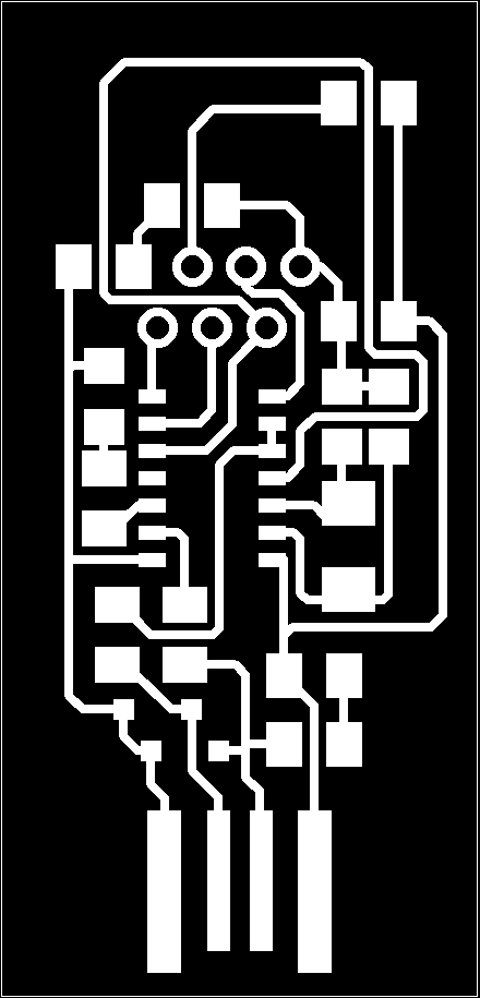

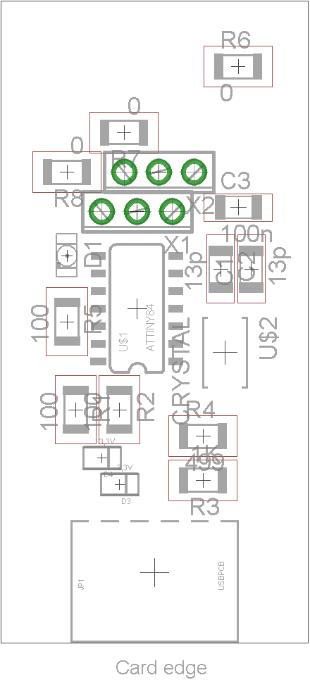
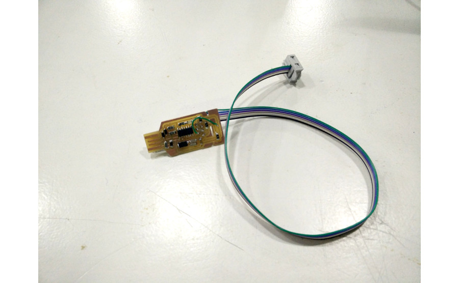
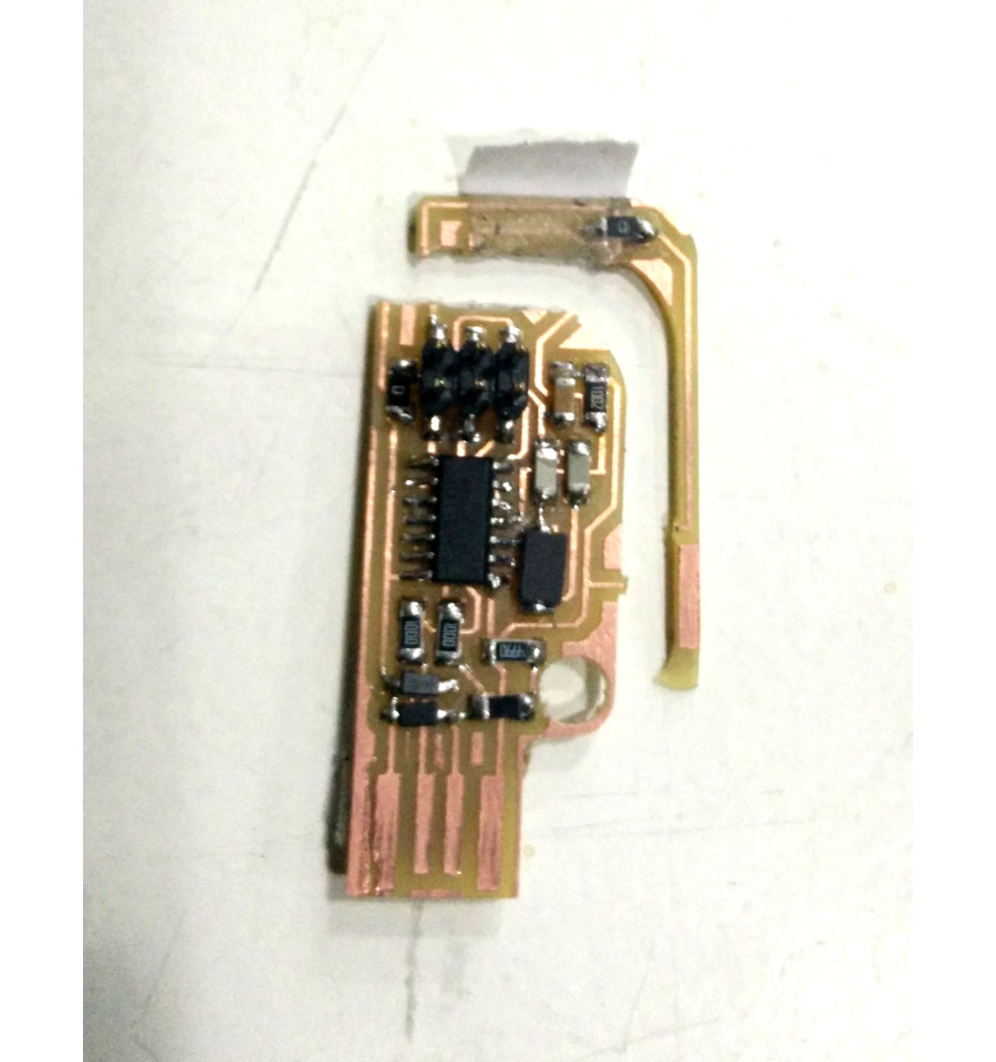
My design milled beautifully except a little shortcut between the cable pads. The green wire in the picture is temporary and due my error disconnecting the shortcut. There is no pin header in the design to prevent you transporting the programmer in a pocket. I made Valentin's design and programmed it. Then I cut off the removable part and used it to program my own design. After a little change to the program we have light! The LED shows the programmer has a functioning program. The LED blinks while programming and stops blinking when the programming is done. The links are for the schematic and board files done with Eagle, and to the main.c file of the programmer. It's the only one you have to change to add the LED.