Trying different software to design the board
Before jumping into the world of Eagle, I was stubborn enough to test other software that looked like they had better UX/UI interface. So I tried to create the board in Fritzing and Upverter. I ended up realizing that these tools are indeed very much user-friendly, but without the component library from the fab labs and the inventory list, it is really difficult, if not impossible, to get the right footprints (especially if you are a beginner).
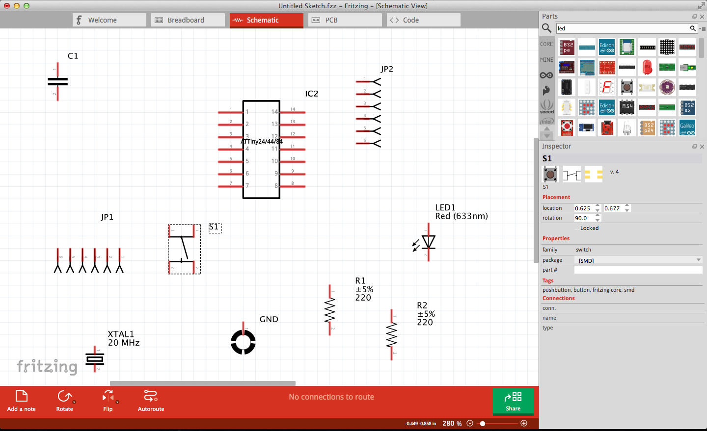
Fritzing has a really nice user interface and it is easy to use, but it is too “arduino-specific”. The end result (PCB board) look really different from the result we see when boards are printed on the Modela. In fact, circuits you design on Fritzing can be ordered to print out quite professionally, so the traces are really thin. So after few hours of playing with this software it was time to abandon it, but I would like at some point to order a board that I designed to be fabricated that neatly.

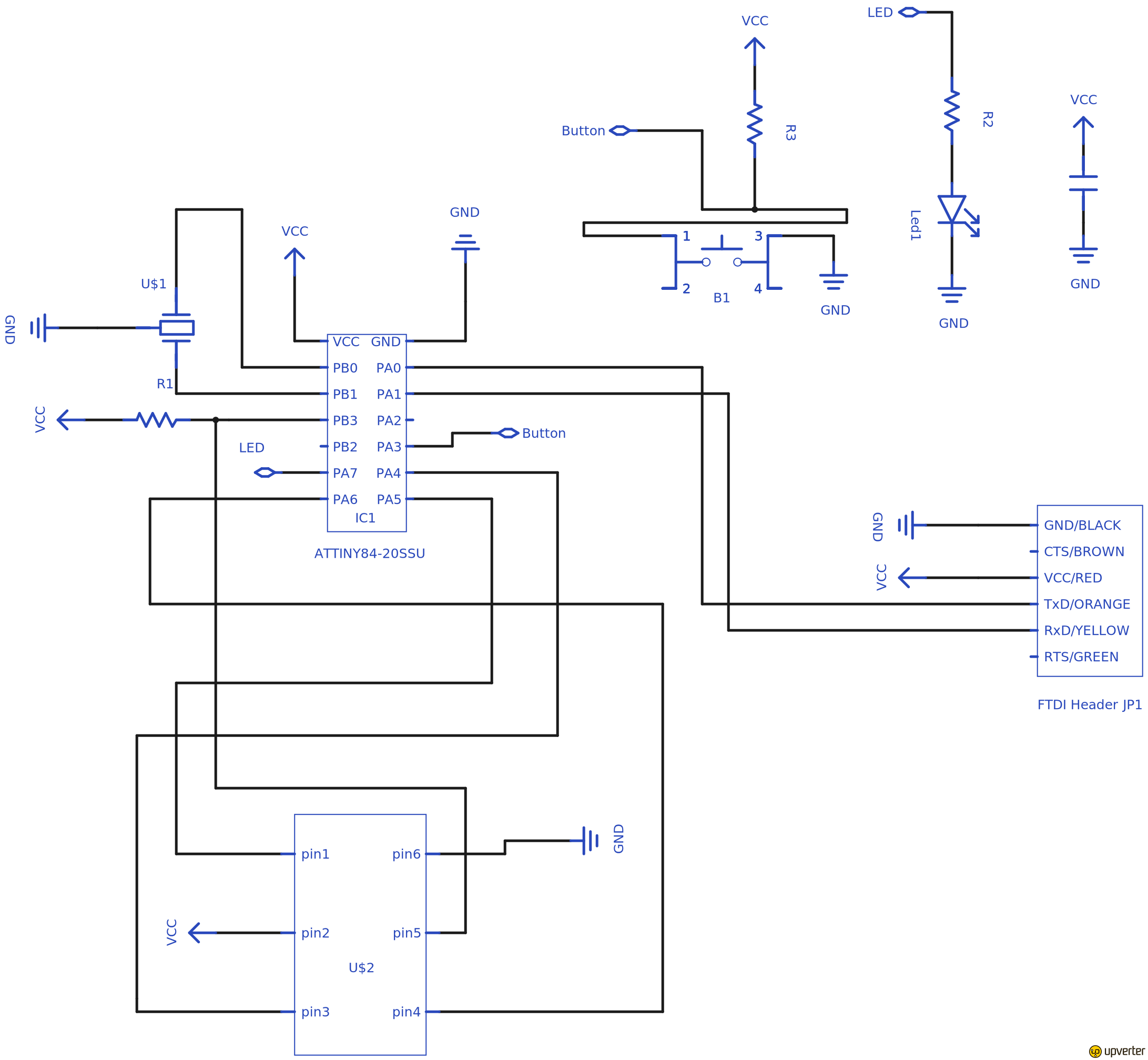
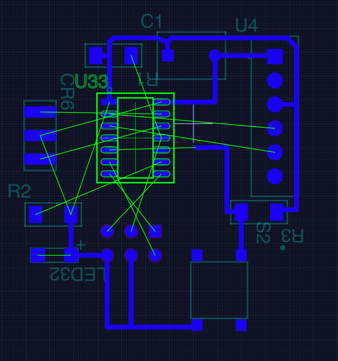
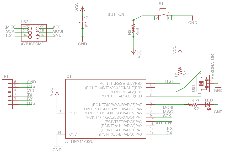
Creating a board in Upverter is quite easy. On a schematic level the library is quite extensive on components (as long as you know which exactly you are looking for). The case was that many times I was searching a bit blindly since I saw the right footprint on the PCB representation. For example, the crystal was oversized in the beginning, the LEDs as well, and I had found the wrong processor as Attiny44 was not in the list and had to replace it with the Attiny84 in the end. However, the most confusing part was that in the schematic some components have different enumerations than other softwares’ representations. For example, the 6-head pin is indicated as: 1-2-3 (left side, top to bottom), 6-5-4 (right side, top to bottom). But in documentation from Eagle the 6-head is 1-3-5 (left side, top to bottom), 2-4-6 (right side, top to bottom). This caused wrong connections and the PCB representation was quite flipped at some points. When you get the connections right at the schematic level, the software indicates what should be connected with green lines. Connecting the rest and filling the copper layer was just few clicks away.
The main issue was that finding how to export the files took me way too long, and when I did the result was inverted. Also I couldn't figure out how to make the traces thicker. Starting to realize that the only way to go is Eagle, since there will always be someone at the lab that can help you with that, so I abandoned hope with that software as well.
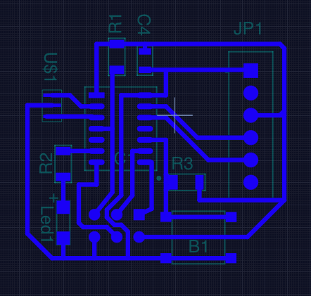
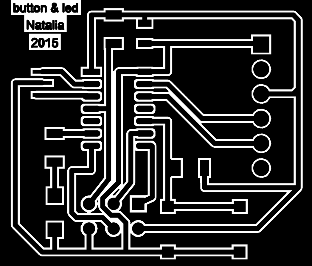
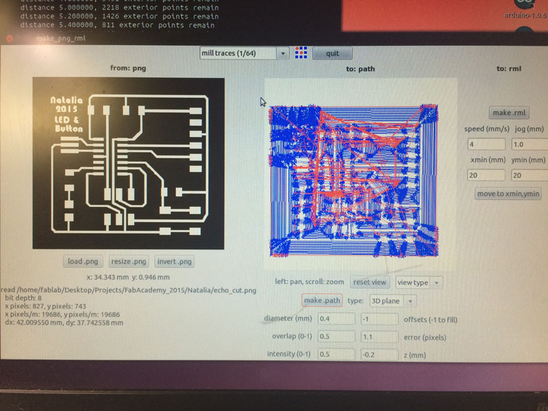
Design the schematic and board in Eagle
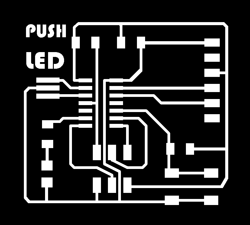
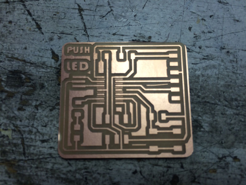
The learning curve of Eagle is trully steep. Without watching some videos, I wasn't even able to navigate around. Many hours later I was able to reproduce the board that I drew twice in other software (yeeeeh)!
First attempt to produce the PCB (failure)
The first attempt to mill the board was a failure. The first thought was that the z needed to be deeper, so I ran the job with a -0.2. But still, nothing happened. I took the plate out and I realized that the copper was not fixed in place properly, so instead of milling the surface the head was just pushing it down just polishing it. That is a lesson to always check if the board is placed correctly (if you didn't place it there).
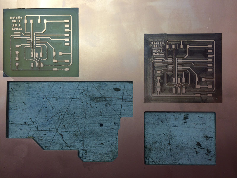
Second attempt to produce the PCB (successful, for a week only)
The second time the board was milled, although rushed into getting it out without cutting it (also, it broke on the side). But, having kept the coordinates, I placed back and was able to perform the cut. The milling head was a bit old, so Zaerc suggested to take a cloth and just clean the board a bit to smooth the rough points. I stuffed the board (even programmed it), but the settings I chose didn't make it really durable. I selected to cut the board through a painful and time-consuming offset -1 (cutting everything but the traces). Plus the traces were too thin, so the ISP header broke, pulling the traces out.
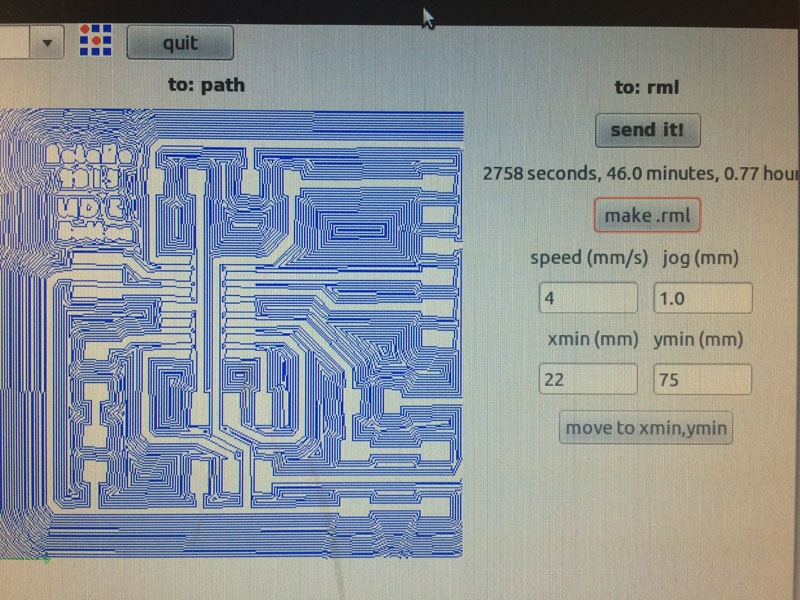
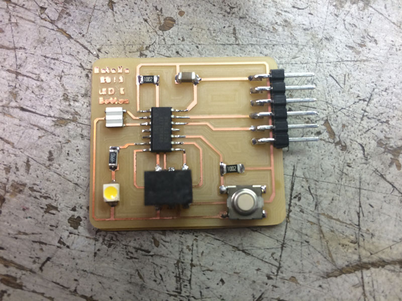
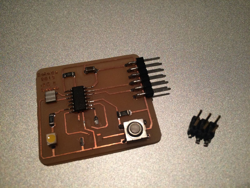
UPDATE, third (and final) attempt (successful)
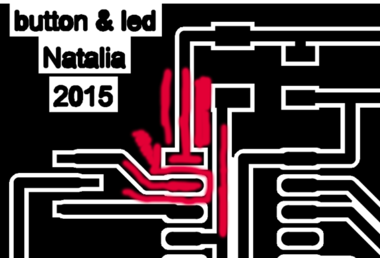
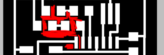
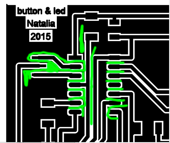
I decided to thicken the traces, mill and stuff a new one (even though I was able to repair at a functional level my old one), so that I have one that will not break so easily again. This time I was a bit nervous with the offset so at the end I had to remove one or two spots with the knife.
More failures and lessons learned
Another failure for this week, I broke the milling head :( While trying to move from one failed mill to the other, at some point I changed the cutting bit to the milling bit while on preview mode without putting it at max height. So when I pressed the move to coordinates, in order to zero the z, the bit run hit the copper plate, and broke!