Week 13
Networking and communications
This week the aim was to design and build a wired and/or wireless network connecting at least two processors.
I decided to control my microcontroller via my computer (with cable) and tried to do it also by bluetooth.
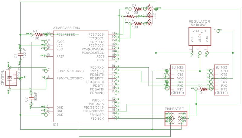
For this I decided to use a new microcontroller : the ATmega 88PB with a USART (which makes programming easier
to communicate with the computer). It was also an opportunity to test this microcontroller because this is the
one I'd like to use for my final project (which also ensures an SPI connection which I will use to transmit
music from an SD card to the speaker). With the old microcontroller (ATtiny44A) I won't be able to connect
SD card easily and I will have to write an entire program to enable SPI link.
So like every time, I began by reading the datasheets of my new components :
- ATmega
88PB
- Bluetooth DIP Module (to communicate
via bluetooth)
- External Crystal 20MHz (to try a new
one we had)
- Regulator 3V3 (to powered the
bluetooth module with 3V3)
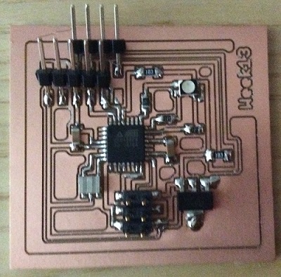
I had already used the other components during previous weeks. So I designed a new board.
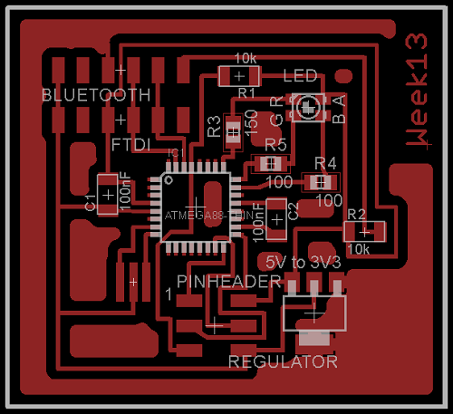
The schematic and the board from eagl are just below.
I made the gcode
(circuit & contour)
directly with eagle and this is a really good tool !
I detailed how I did it in the mini tutorial below. You can also see the eagle file
here.
************************************************************

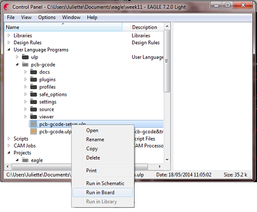
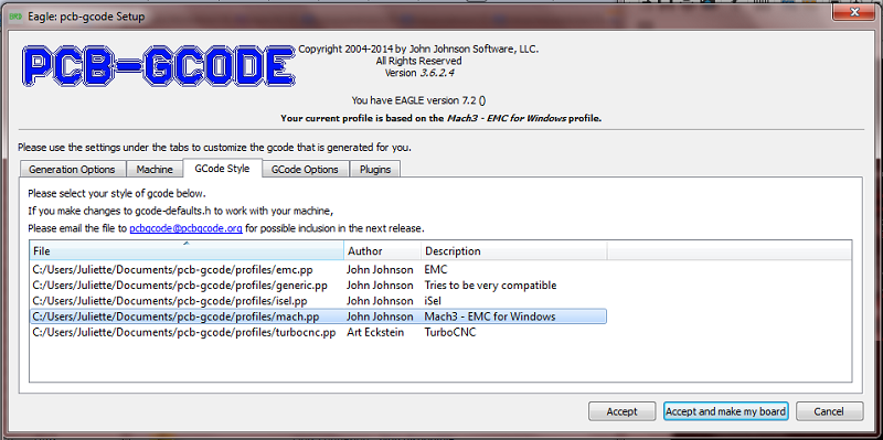
- First you have to download the pcb-gcode-setup.ulp
here and put it in your folder eagle with the other .ulp files.
- Then open your board and in the main window of eagle, find User Language Programs -> pcb-gcode ->
viewer -> pcb-gcode-setup.ulp.
- Click right -> Run in board.
- A window opens by itself and you just have to choose the settings. You can use the same that with the fabmodules but pay attention to the units, they are different !
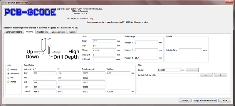
- Finally choose your machine. Mine was not in the list but I chose Mach 3 and it worked perfectly !
You obtain a .tap file and you just have to open it in WordPad and save it as an .nc file.
I also add a line T1 M06 (tool change) after the line G21 (metric) because it was missing.
For the contour I added T2 M06 because I didn't use the same tool
(trace -> endmill 0.4mm ; contour -> endmill 3mm).
!!! The contour on eagle is in gray for "Dimension" but you have to change it into "Milling".
Otherwise your gcode_contour will be empty ;) !!!
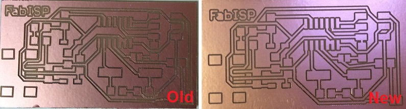
To convince you, I had to remake my FabISP because I broke it and the result is much more better!
The gcode looks better.
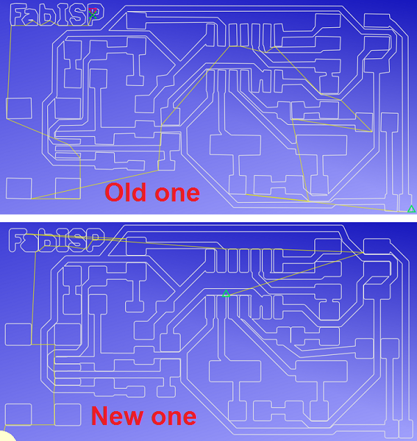
And the final board looks better too (: and especially it was easier to solder because the pads are thicker !
************************************************************
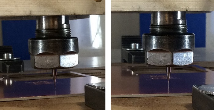
So I made my gcode with eagle. I found a new way to set the origine Z. The surface of the pcb is like a mirror and with my camera I zoomed to choose the origine more precisely. It works much more better like this (:
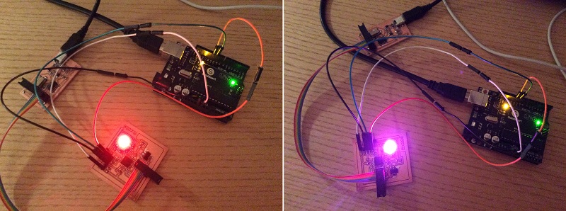
I milled my pcb, soldered my components and I obtained my new board for this week.
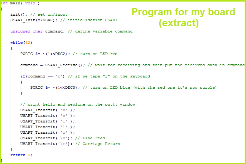
After after a few hours spent on the datasheet, wikipedia and instructable I wrote a simple programm for my board and another program for my arduino. I had to program my arduino UNO because first I used the tiny arduino board in the fablab to communicate with my computer but then, I wanted to use my own arduino UNO (which is not especially made for that unless we program it to do it.
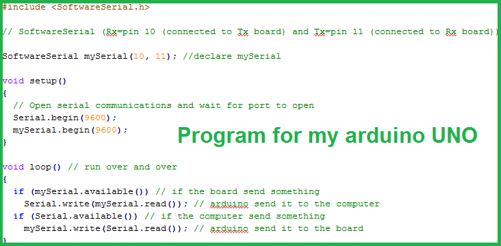
I then download Putty here and chose the same settings as I did in my program for my board to enable the communication with USART. I know we can do it easily with the Serial Monitor on arduino but I wanted to try something new that I never tried before.
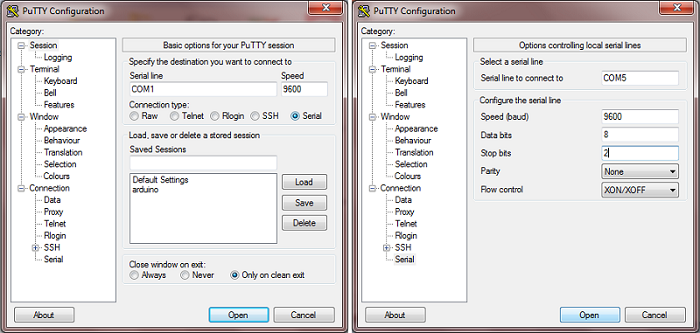
A window opened and after few small issues I managed to get a hello from my board when I was typing a key on my keyboard.

And when I pressed the key "r", the blue LED was lighted and the RGB LED thus became purple. Now I know how to transmit and receive informations between my computer and my board (:
Unfortunately I couldn't use the Bluetooth module this week because I didn't realised that I had to power all my board with 3V3 and not only the Bluetooth module because the module can't support 5V, it won't understand the received datas like this. Good thing to know because I will have to do that for my final project.
Software and website used