My final project
¤ Digital fabrication : Applications & Implications ¤
Now it's time to organize the next three weeks to successfully finish my final project. I decided to stay on my first idea (the alarm clock) but with some changes.
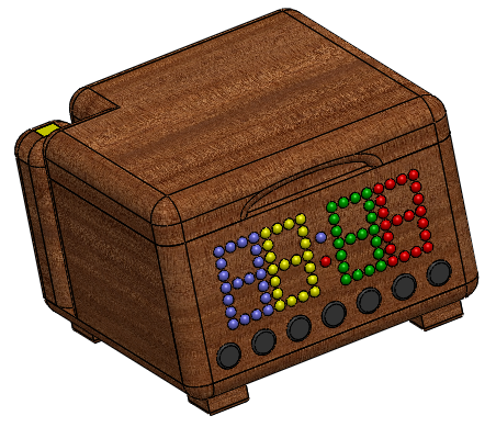
¤ I would like to make the box in a single piece of wood that I'll bend. I already made several
tests with wood I will use, and it is feasible, I only have to design it properly.
¤ Regarding the display, I'd do it with RGB LEDs and cover it with a small opaque plate to give
a nice effect. I need 82 LEDs and it's really not easy at all but I've almost settle this trouble!
¤ For the music I changed my initial idea. I would like to use a micro SD card because
this way the mp3 decoder can retrieve my song and then the microcontroller can send it to the speaker.
¤ I'll add buttons to set the time and alarm, to activate/deactivate the alarm, reduce the
brightness of the LEDs and adjust the volume.
I made a list (below) with everything I will need :
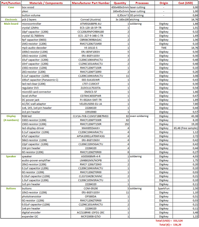
My final project costs 140 €. I did not imagine at all that it would cost too expensive (I was very surprised by the cost of certain components). But it is good to know that for my future projects.
I think I have a solution for each "problem" now and I just have to do everything. The most complicated
part will be programming I think for me.
So finally to evaluate my project in the end it will be quite simple :
1. it must be a small wooden clock
2. it must be possible to set the time and alarm (time and on/off)
3. it must be able to vary the brightness of the LEDs
4. the music that wakes me up must be the one I put in the SD card
5. it must be possible to change the volume
¤ Invention, Intellectual Property, and Business Models ¤
Concerning my first idea to make a kickstarter project with my alarm clock, I changed my mind. Firstly because this is absolutely not finished. And because I have some better ideas. That's why I decided to choose an open license. In that way, I will maybe help people to learn what I learned. For the hardware I chose Creative Commons.

Wooden_alarm_box from Juliette Koch is available under the terms of the licence Creative Commons Attribution 4.0 International.
And for the software I decided to use the MIT license. For this I added the sample text below in my code.
Copyright (c) 2015 Juliette Koch
THE SOFTWARE IS PROVIDED "AS IS", WITHOUT WARRANTY OF ANY KIND, EXPRESS OR
IMPLIED, INCLUDING BUT NOT LIMITED TO THE WARRANTIES OF MERCHANTABILITY,
FITNESS FOR A PARTICULAR PURPOSE AND NONINFRINGEMENT. IN NO EVENT SHALL THE
AUTHORS OR COPYRIGHT HOLDERS BE LIABLE FOR ANY CLAIM, DAMAGES OR OTHER
LIABILITY, WHETHER IN AN ACTION OF CONTRACT, TORT OR OTHERWISE, ARISING FROM,
OUT OF OR IN CONNECTION WITH THE SOFTWARE OR THE USE OR OTHER DEALINGS IN
THE SOFTWARE.
¤ Digital Fabrication : Project Development ¤
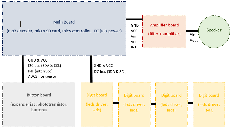
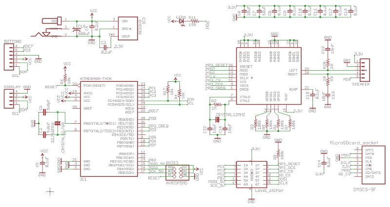
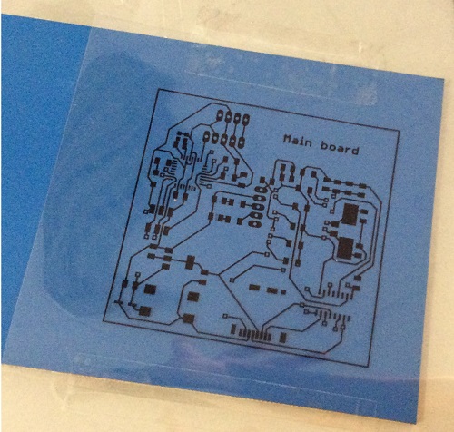
I started with electronics because I knew it would be the most complicated. I designed on eagle the main board, one board for the speaker, one board for the buttons and 4 boards for the 4 digits of my display.
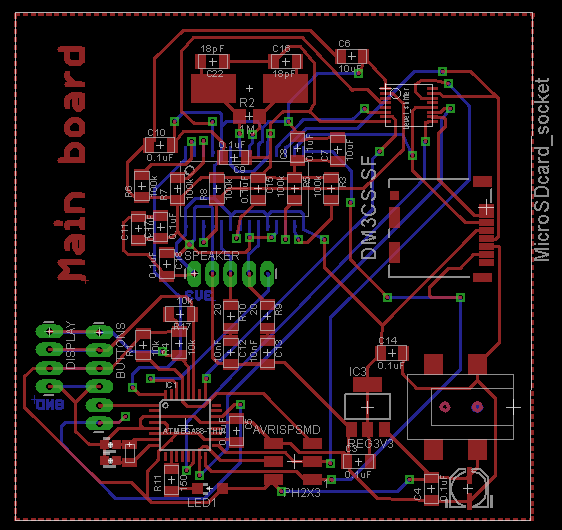
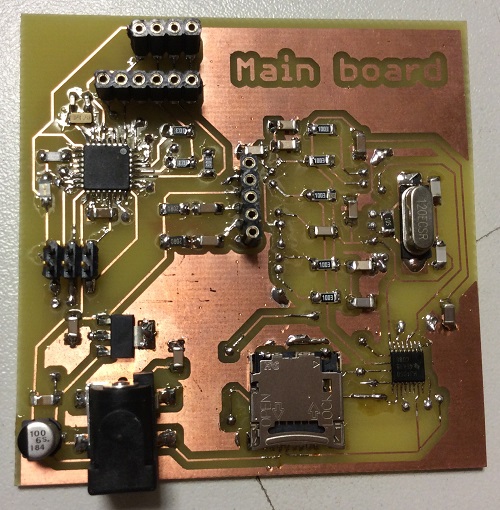
On the main board I put the microcontroller, the mp3 decoder (with the level shifter), the socket for the micro SD card, the power supply and the different connectors for the other boards.
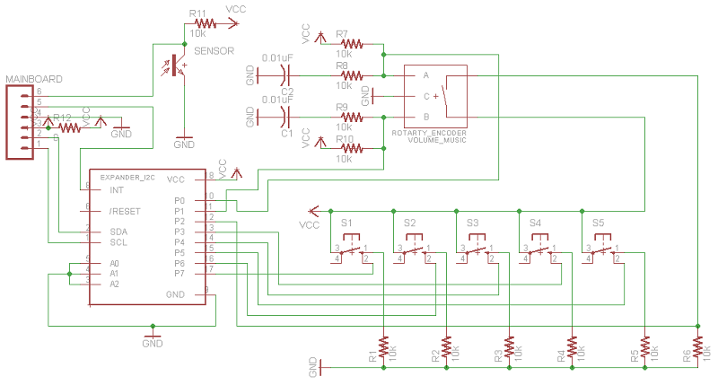
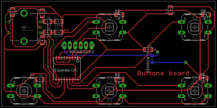
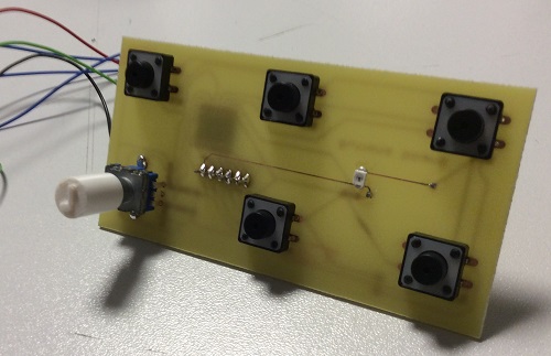
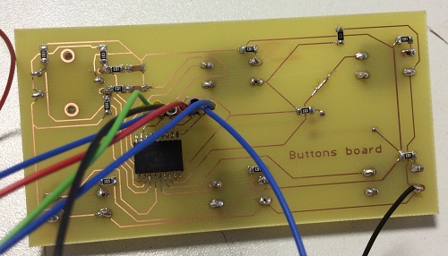
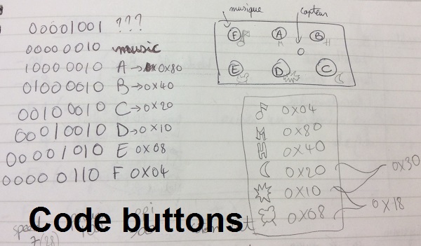
On the button board I put 5 simple buttons, a digital encoder, a phototransistor and the I2C expander.
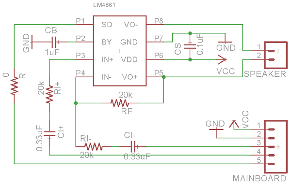
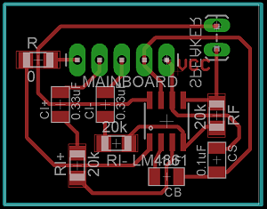
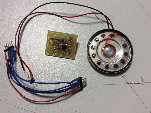
On the speaker board I put an amplifier, a filter and the speaker.
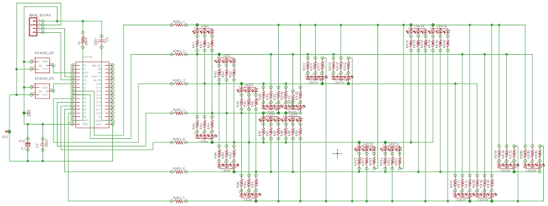
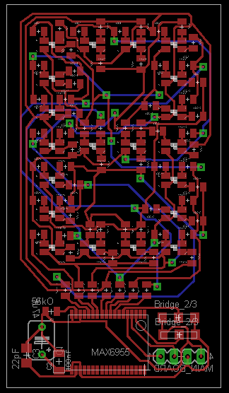
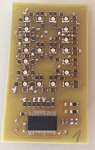
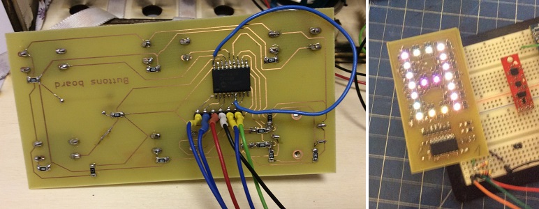
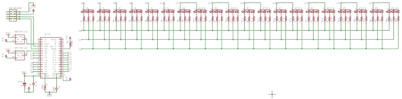
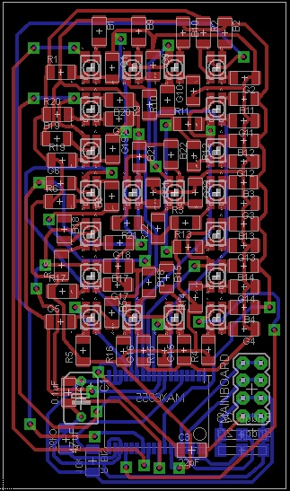
On the digit board I put the LEDs and associated resistors (a lot) with the led driver MAX6955. This board was the most complicated to design because of the very large number of components. For this reason I decided to etch the pcb instead of milling (in that way I could make thinner traces).
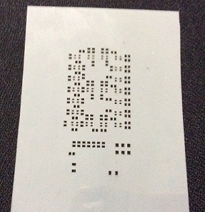
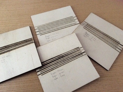
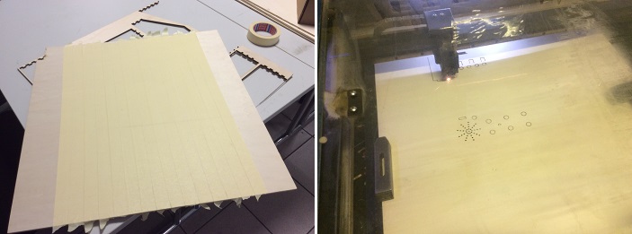
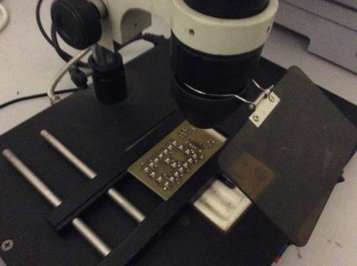
To sold the components it was also really long that's why I tried a new way to solder : with solder paste and an oven. For this I cuted a mask with the laser cutter (photo below) in order to put the solder past properly. And placed my components and then I put my pcb in the oven during 3 minutes. I have four times the same board for my display so it's really usefull !
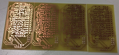
And here is the result ! First I have made just one to try to program it before making the other digits. And I also made bridges with wires which was really long so for my next boards I will use double layers pcb !
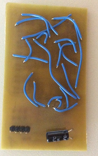
For the other boards I used double layers pcb and it was easier to etch instead of milling. I just used tape to place the two sides exactly on the good position.
I made the holes with a small drill (Ø1mm, Ø1.5mm and Ø3mm).
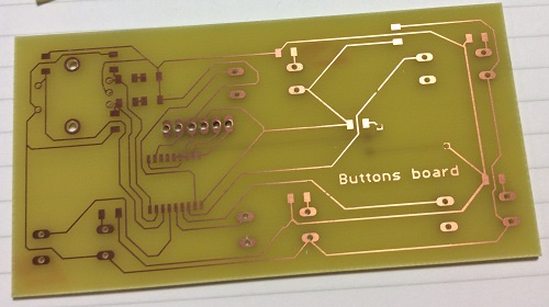
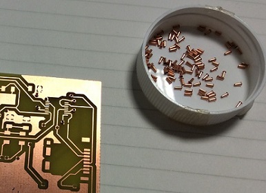
And instead of cutting wires to make the vias, we ordered some little pieces in copper (Ø0.6mm and Ø0.8mm). Simply place them in the holes, bending them on the other side and sold them on each side.
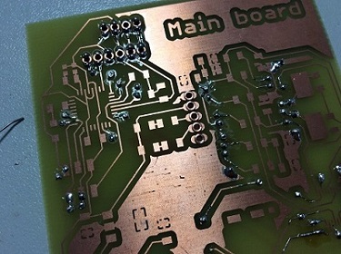
I soldered all my components on the differents boards which was quite long.
I made a button with the 3D printer have a nice the digital encoder to change the volume of my music (:
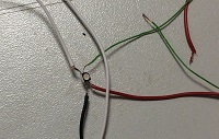
I also had to make some wires myself, which is not complicated but quite long.
Once finished all the electronics I started to do tests to bend the wood I wanted to use.
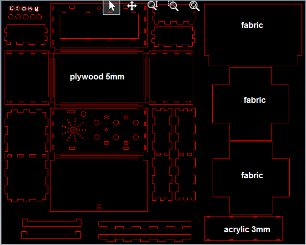
After that I finished to design the box on solidworks and I cutted it.
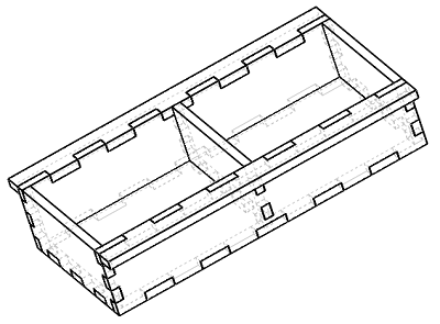
I decided to put tape on one face to protect the wood and to have a nice finition even inside but the tape melted and it was worse with tape than without.. And I had some other small problems but after the second try everything was perfect.
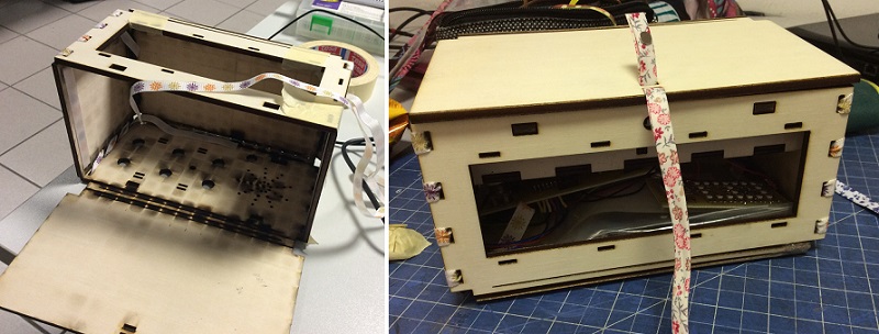
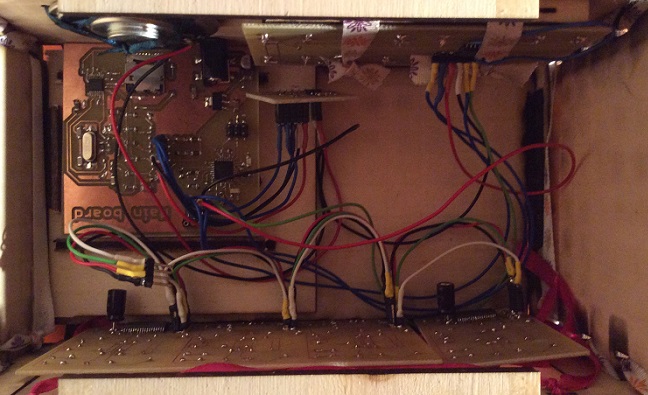
It was a little bit dark inside but I am the only person to see it when I program my main board! I have attached everything but just with ribbons so it is possible to remove everything in case I have to change something afterwards (on the box or on boards). And I had a magnet to close the box.
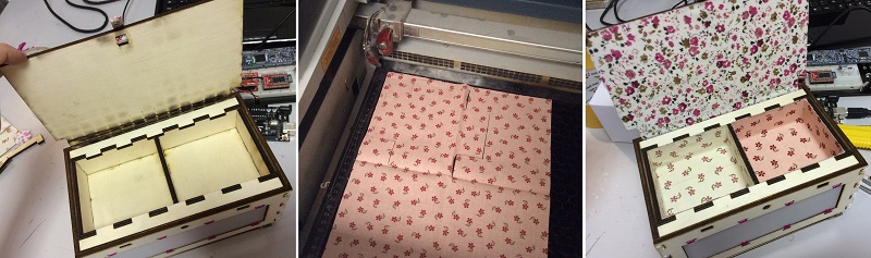
Because it was not really nice to see the dark traces, I have tried to cut fabric on the laser cutter and it worked very well, so now we see flowers instead of dark traces.
Outside my box is completely finished! I added an acrylic screen that lets light LEDs (I tested before), I cut / engraved pretty buttons and access to the jack and micro SD card is properly aligned.
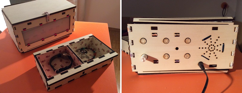
Inside it's a bit messy with all the ribbons and 7 boards but everything is connected properly.
The "mechanical" part took me 3 days, but it was not the most complicated, after a few tries
everything worked. I chose to do this project because I wanted to learn electronics and programming
(knowing that the 2D / 3D design is something that I learned in my school).
So I had already spent many hours choosing my components, then to make the schematic and the boards
(especially the screen and the main board). And now I have to write the program.
Obviously during the first test nothing worked x)
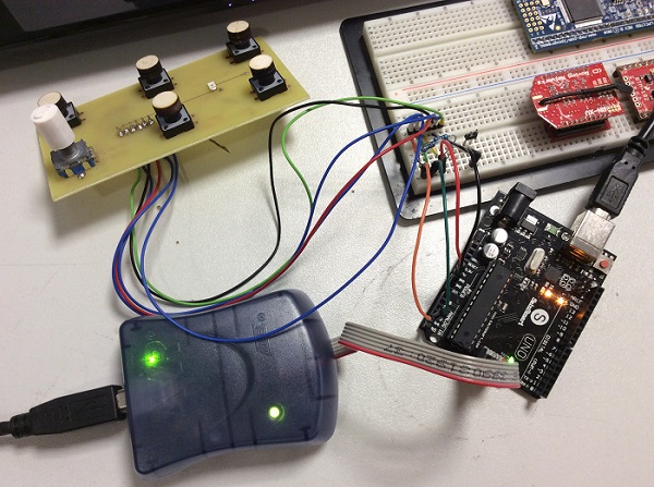
The problem is that I had not thought to put something on my board to communicate with my
computer to see where the program was not working. So I used my Arduino by programming its
microcontroller directly (from atmel) to test my code and then reuse it on my main board after.
I had great difficulty in solving my problems especially for i2c communication I needed for my buttons and the screen. It took me over a week to try everything I found on the internet and the advice of the LabManager. I had a UART communication and a comment between each of my lines of code (I used Hterm this time instead of putty, I prefer this one for simple serial communication). I changed the resistors, connected the reset pin, changed my i2c function, changed my code, desoldered some components, resoldered some components... And on Saturday I received an answer from my buttons !!! And the day after I finally saw the light from my display !!! And I also tested my main board which I think works because I can turn ON the leds on it and I receive data from the phototransistor. And I also tested the speaker that emits sound!
Unfortunately I had misread the datasheet or not well understood and the wiring I had done was not appropriate. It was impossible to control the LEDs and even turn off all of them at the same time. So... I remade the schematic and the board.
This time I made the four at the same time because I knew that it should work. And I used double sided pcb because it was really impossible without that. I etched the pcb because the spaces between the traces were really thin. I made all the holes by hand and I cuted a new mask to apply the glue to sold. Unfortunately my new design (smaller than the first) was too small and the mask did not work. That's why I soldered 80 LEDs and 240 resistors by hand. It was long but not so hard (:
To redo my digits I desoldered the MAX6955 so I also used a new tool: the rework station (super useful) !
After many hours of soldering... tadadam !!!
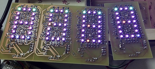
I was very happy to finally see my display working and finished. But.. It was still not possible to control the leds and I didn't know why. The reaction of my display was unbelievable. In my opinion it was a software issue. That's why I retried to make tests with my arduino. But after one day without any result I decided to test my leds.
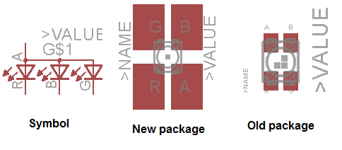
And I found the first problem ! I used the old package from the fab library on eagle because the new one was so big that it didn't fit in my design. And between the old package and the new one, Vcc and GND for green are inverted... But they have the same symbol so I didn't realize... After that I used the rework station and turned my leds on one digit (blue and red were inverted too but it was not a problem).
I finally could see the green but it was still not possible to controll the leds one by one. And after few hours I found one line in the datasheet which say that I need a common cathod to wire the leds on the max and my leds are common anode. So... I finally know why it doesn't work but I have no time to order new leds, remake the digit board and solder everything before the end of the fabacademy. :( I tried to find an other chip pin compatible with the MAX6955 which works with i2C and charliplexing and common anode leds but of course it doesn't exist (at least I didn't find one). But because the rest of my alarm clock works, I will order a display (already made) which works with I2C ! For now this is a light when I plug it x)
Concerning the buttons, I used the serial communication on my arduino to check wich button set which bit to one in the GPIO register of my I2C expander. Unfortunetely I coudn't test my big program because I need a display to set the time or the alarm, etc. But I know that my main board works because I can light the display. (:
For the music I didn't have so many time to write the program. I used the arduino libraries, some sample code on Sparkfun and finally the code of the FabBoombox (an other project from one student of the FabAcademy : Matthew Keeter). I modified some parts because I have a mono speaker and not a stereo and I have only one song on the micro SD card. I tested this part of the program and I managed to heard music from my alarm clock but with a really bad sound. Maybe because I chose a really bad speaker (the cheaper) or I made a bad filter. This is good to know for my next projects ! Finally, I didn't introduce this part in my big program because I can not test it without a display... But it should work and I already know that the hardware works.
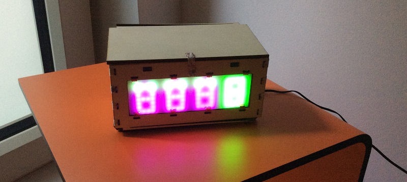
After a lot of work I have an alarm clock with bad sound and no display. In fact now this is a box and a light x) But I'm really happy to have made this big project : in February I was zero in electronic and programming and during 5 month I have learned so many stuff ! How to read a datasheet, how to choose a component, how to make a circuit on eagle, what is important, how to wire the component using the datasheet, how to program the board using the different datasheet, how to look for solution on internet (very important !!!) and what to do when nothing work to find the problem. I'm now ready to remake my alarm clock this summer: one which works correctly (;
All the files to build my alarm clock (which need to be improved!) :
- Bill of materials
- Eagle files for all boards
- DXF design box (and Solidworks)
- Solidworks volume button
- Program files in C