Classes and Final Project
week1 : principles and practices, project management
week3 : computer-controlled cutting
week4 : electronics production
week5 : 3D scanning and printing
week8 : computer-controlled machining
week13 : networking and communications
week14 : machanical design, machine
week15 : interface and application
week16 : applications and implications
week6 : electronics design
Assignments
Redesign the echo-helloworld board and add the componets.(for example, button and LEDs.)
EAGLE
To design circuits boards, the most famous software is EAGLE. In EAGLE, we can design not only the schematic but also the board. After designing the board, we can export the image and mill it by a PCB milling machine. Anyway, I think the EAGLE is not userfriendly interface actually. If you want to put componets, you need to choose from the tons of libraries. It has the serch option, but it only shows the componets with its name. Additionally when you want to move the componets which you put, you need to select the move buttuon and then click the center of the compoent.
After using the EAGLE for desining my circuit board, I learned some techniches to draw the beautiful schematic and board.
- Don't think which components I should connect, otherwise it will get messy. Think like here I put the component (first you should put the biggest component center of schematic), then which components are related on. It's like the thinking of object-oriented programming. Absolutely the main parts are componets, not wires.
- In schematic, put VCC and GND as each components need. you shouldn't share the same sign of them. Also put the VCC up side and put the GND bottom side of schematic will look good.
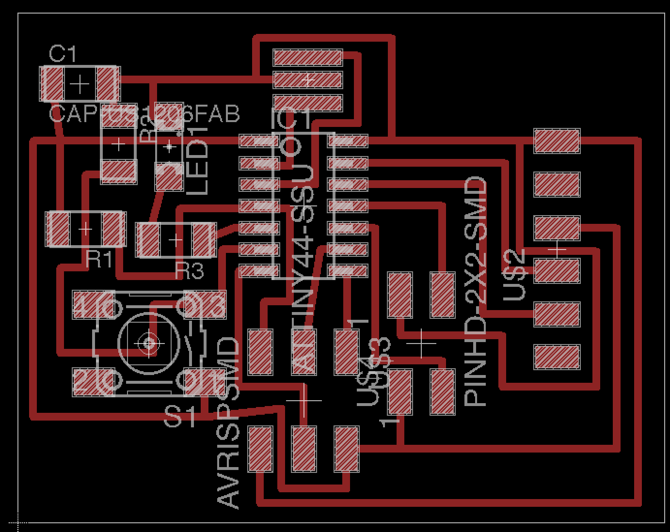
- In board, put the big commponents first, then you should regard resistors and capacitors as the bridge. You can't put the line across other lines in one layer, and in this case, a resistor and a capacitor can be bridges.
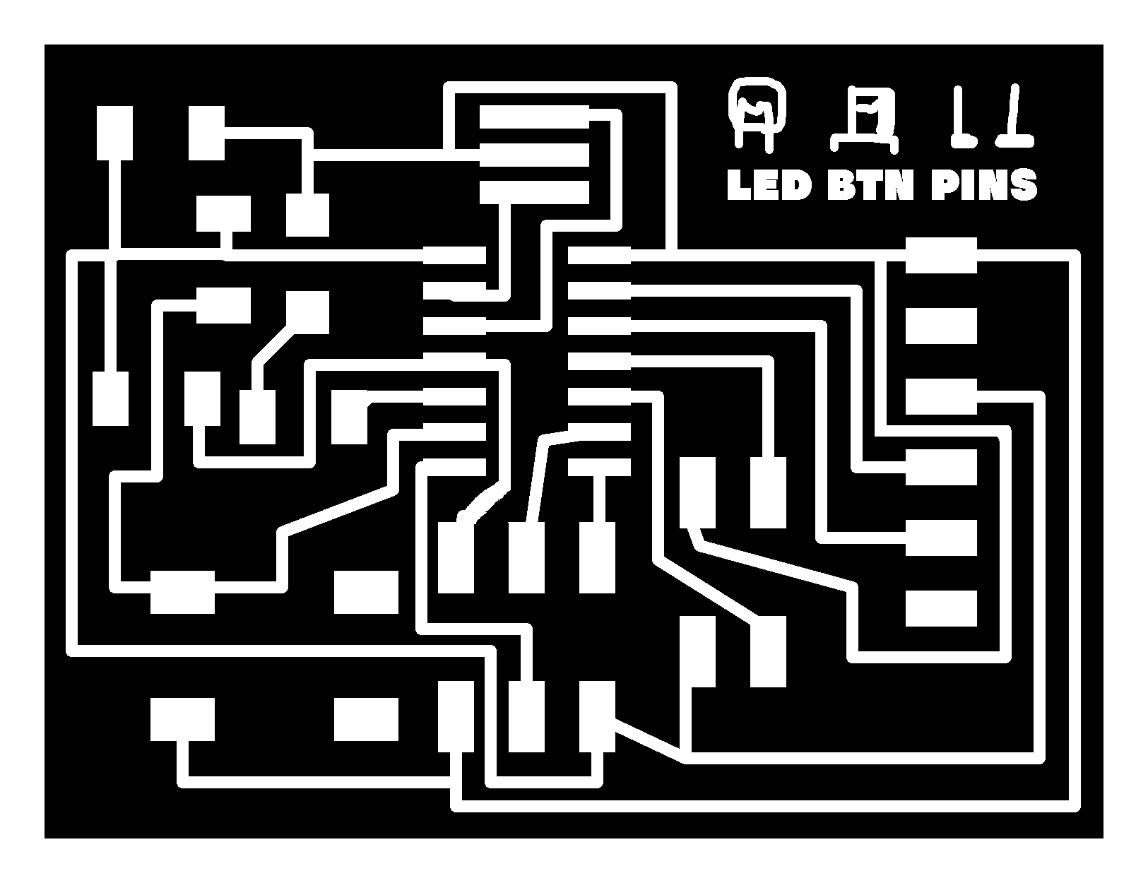
After drawing the board, you can export the board as a grayscale image. The FabModule can laod this image as where the milling machine mills.
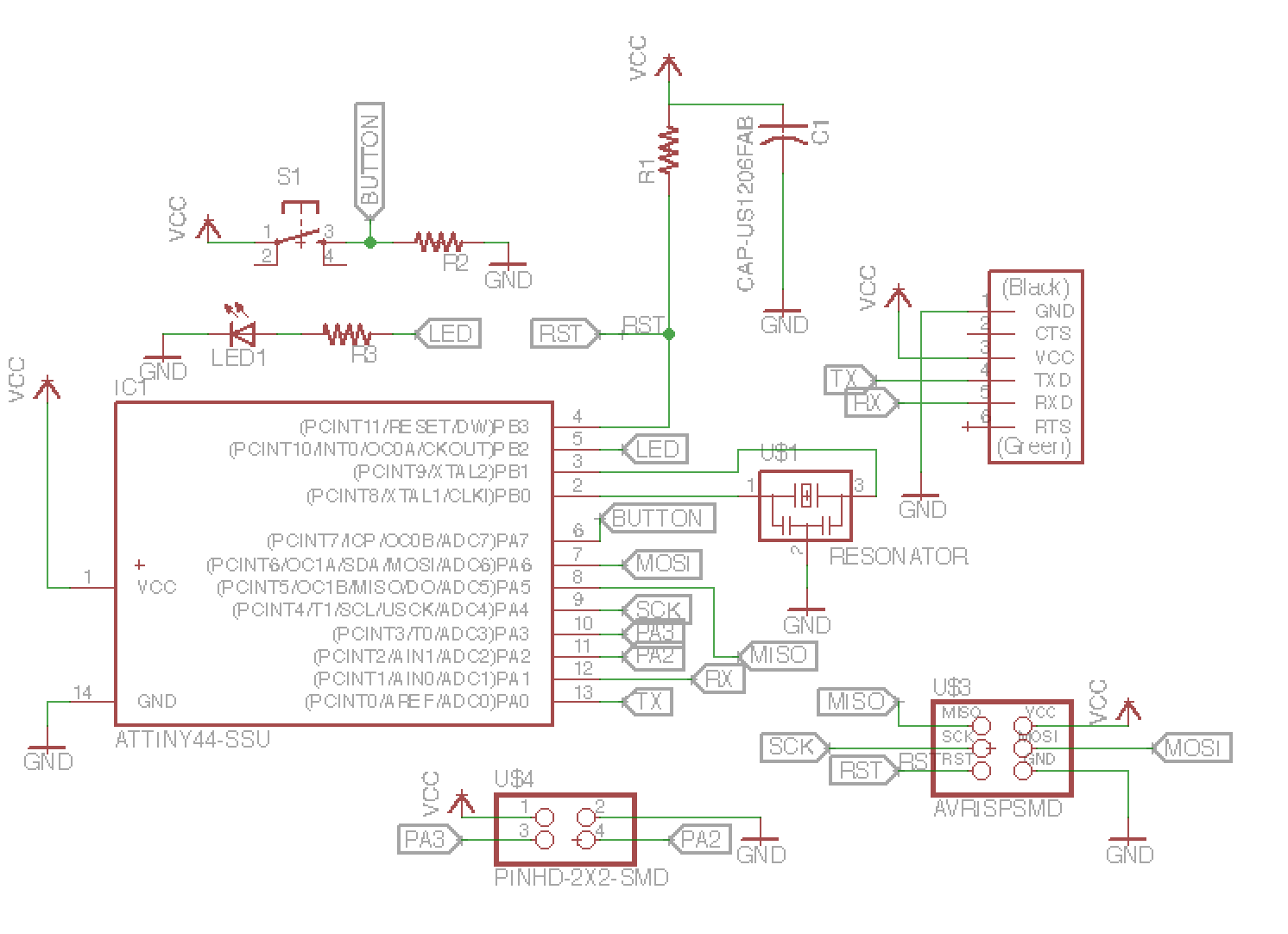
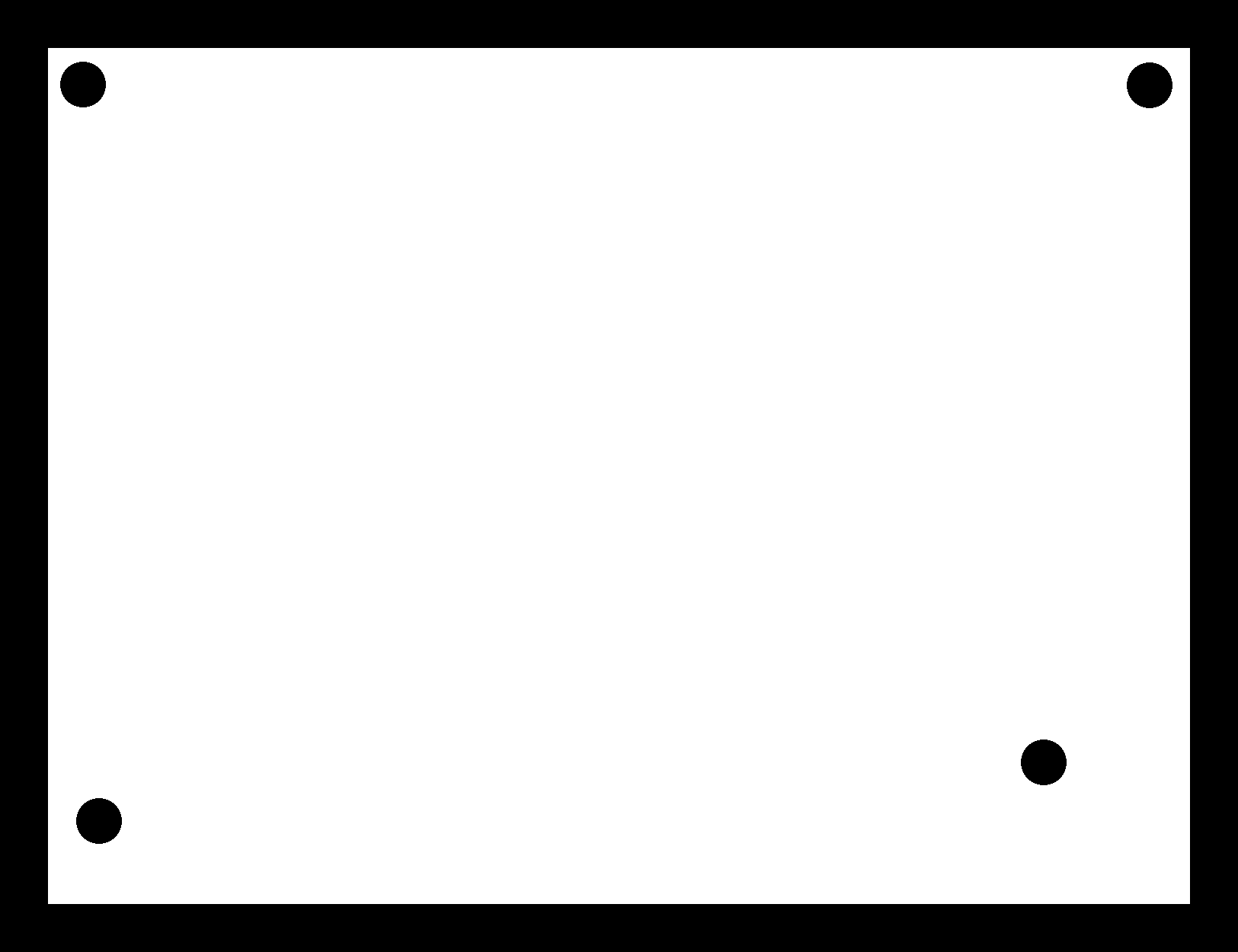
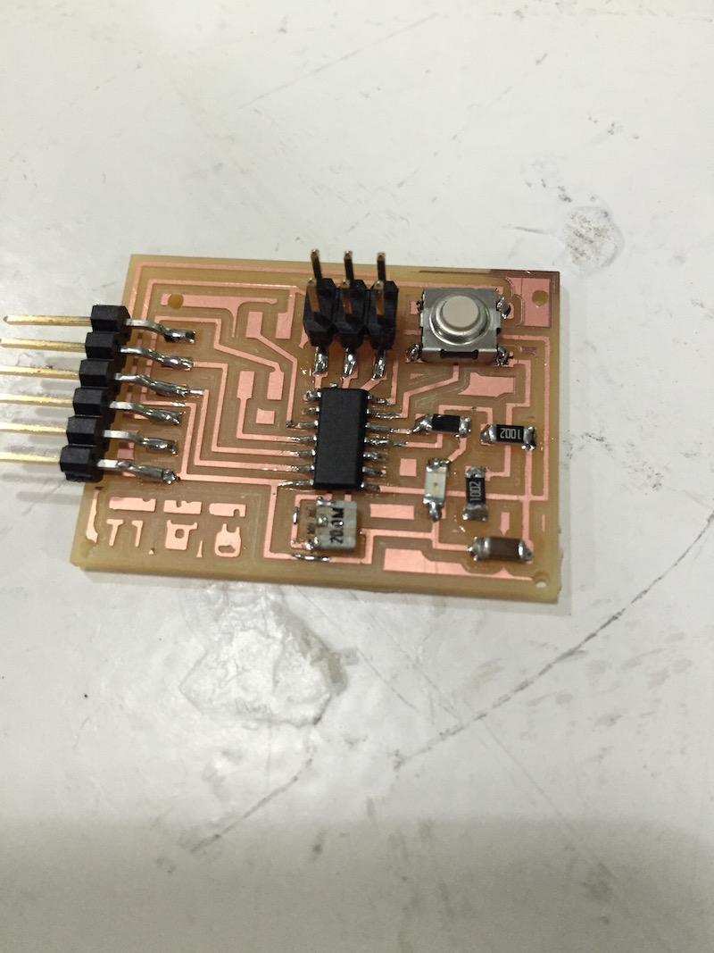
I made holes to knit it on a cloth in order to make it as like a wearable device. It has 1 button, 1 LED and 4 pins adaptor for using 2 free pins (other 2 pins are for GND adn VCC).
Milling
To mill the board, first I needed to change the image size for getting offset. The offset length is 1.6mm. When I changed it by photoshop, I exported it as saving as web image, but in this case the FabModule couldn't load the image. So it's needed to only save as "save". Also it shouldn't be saved as full color image (it has full color data even though it looks like black and white image.). Keep the grayscale image mode, and export it as "save".
Soldering
I did soldering couple of weeks ago and got used to it, so it was already not difficult for me. However, I put the 4 pins adaptor and the 6 pins adaptor closely, then when I tried to connect it to the FabISP, the connector hitted the 4pins adaptor. Hopelessly, I removed the 4pins after all. Next time I need to take care about it.
Burning bootloader and programming it
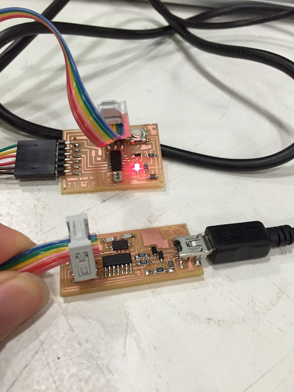
I think this week assignments are only designing the circuits board and soldering it, but I was not sure it worked correctly. So it's next week assignment actually, but I tried to program it. To program it, first I needed to burn the bootloader by FabISP. I connected it to FabISP with 6 cables, then also I connected it and FabISP to my laptop. I opened the Arduino software and loaded the library for attiny44(I found it in student archive 2014). then just I followed this website. http://highlowtech.org/?p=1695 (I will write it next week in the webpage of 7thweek.)
After that, I could use the Arduino language for programming Attiny44. Then the differences between Arduino and Attiny44 are only pin numbers. I sent the blinking programs to the device and it succeeded to blink with LED.
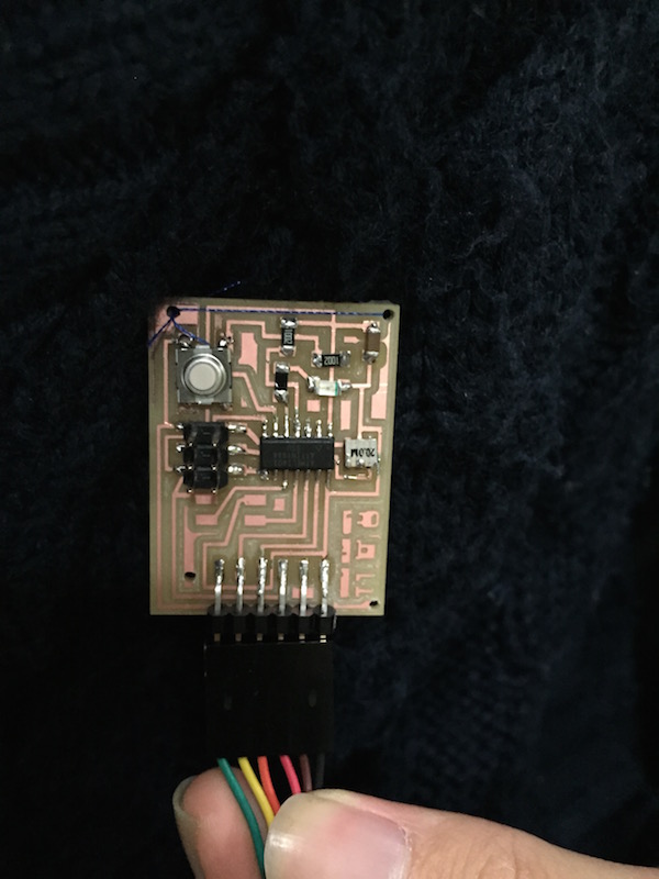
Finnaly I knitted this with my sweater. Here I had a sweater that had a button and a LED, and when I pushed the button, the LED turned on.
Strange thing happen
When I tried to send the blink program to my board on my mac, the problem was happen. It didn't blink, even though the LED turned on. Additionally, if I connect it to a windows computer, it worked well correctly. Then I guessed the reason is because of my USB on mac or the board, so I made sure that the solder were surely on the connections. But still the problem was happen. Then I tried to reset the ATtiny44, and it worked. As a result, when I connect it to my mac with FTDI cable, if I connect the FTDI cable and my mac first then connect the FTDI cable and the board, then it worked. However, if I connect the FTDI cable and the board first and connect the FTDI cable and my mac, it didn't work. I don't understand why it was happen at all, but anyway, I can use boards with this way.
All Eangle files, trace and cut_out files in this week are here.
Enjoy milling!