This Week's Assignment
This week's assignment was to design and build a wired and/or wireless network connecting at least two processors.
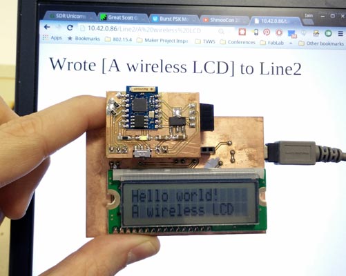
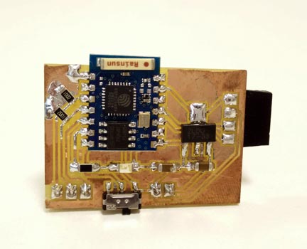
I decided to do both. I made a wireless module for the character LCD board I made for Outputs week. The module uses an ESP8266 WiFi module to receive commands from the local network and then writes strings to the LCD board using I2C.
Here's the final result:

Designing The Board
The board I designed this week is made to plug into my LCD character display board. The targets for the design were:
- Use an ESP-03 module (as that's the SMD version I happened to have to hand)
- Regulate the 5V of the LCD board to 3.3V for the ESP8266
- Use I2C to communicate between the LCD board and the WiFi board
- Have an onboard LED for debug
- Have a switch to control booting the ESP8266 into programming mode
The schematic is pretty simple. So simple that I never bothered checking it properly and initially forgot the pull-ups on the I2C lines. Woops! Here's the fixed version:

The layout is a nice simple one-sided board. Note that pin 2 of the voltage regulator is both pin 2 and the tab, so they are internally connected. I couldn't figure out how to tell KiCAD that this was the case so just ignored the DRC error of the net not being connected.

My initial tests with the board kept giving me I2C errors and it was at this point I realised I had forgotten the pull-ups on the I2C lines. Instead of cutting a new board I managed to jerry-rig some resistors onto the non-functional board.

The Software: ESP8266
I wanted to program the ESP8266 directly but couldn't face setting up the SDK. As luck would have it, an Arduino IDE port for the ESP8266 had just been released. Beware that I found release 1.6.1 had problems with the I2C implementation so I had to build the IDE from source. Since I got started, it's been made even easier to add ESP8266 support to the Arduino IDE using the new Board Manager. I've not tried this though, so no promises!
There's nothing particularly exciting in the actual code. I used the ESP8266WiFi/WiFiWebServer example as a starting point. HTTP requests to the ESP8266 cause different behaviour:
http://server_ip/LED/onturns the LED onhttp://server_ip/LED/offturns the LED offhttp://server_ip/Line1/{some string}writes{some string}to Line1 of the LCDhttp://server_ip/Line2/{some string}writes{some string}to Line2 of the LCD
In each case, an appropriate HTTP response is sent to the user browser. For example, typing http://server_ip/Line1/Hello world! in a browser (with server_ip replaced by the IP of the ESP8266) will return the message Wrote [Hello world!] to Line1 if the I2C write was successful or Bad I2C write! if there was an error. It's worth noting that you can't send spaces in an HTTP URL - they get converted to %20. The ESP8266 searches for this string and replaces it with a space. This might be browser specific (I use Chrome) - I haven't tested any other browser to check!
The Software: PSoC 4 LCD Board
The code I posted for Outputs week for the LCD board was extremely basic - it just wrote a message to the LCD and didn't actually implement the I2C/UART/SPI interface I envisaged for writing to the display.
To talk to the ES8266 I decided to use an I2C interface, with the PSoC acting as a slave. I used the EZI2C component in PSoC creator, which sets up hardware I2C that acts like a common I2C EEPROM.
My "protocol" for writing to the LCD is rudimentary for now. The procedure for the master to write to the LCD is:
-
Write to I2C address (the default is
0x08) -
Write the memory address to write to. The first 100 bytes are for Line 1 and the second 100 bytes for Line 2. i.e. use
0x00to write to Line 1 or0x64to write to Line 2 -
Write the zero-terminated string you want to display on the LCD
For now, short messages are automatically padded with spaces so that the screen is cleared on each write. Messages that are longer than 100 bytes get chopped. Although messages over 16 characters are accepted, only the first 16 are shown on the display. In the future I might extend the software to have longer messages scroll.
Putting It All Together
The current implementation is pretty basic, but still shows the overall workflow for WiFi and I2C (which is all that's really necessary for this week). Here's the screen in action, although you'll just have to trust me that this actually functions and isn't just an elaborate scam.

The generic hardware has a lot of potential. One nice idea I have for the setup would be to have the ESP8266 access the web API for the software we use for booking out the machines in our lab. That way a display could be used to show the upcoming bookings for each machines.
Get The Files
I flat out admit that the code isn't exactly what I would call pretty (especially the code for the ESP8266!). It is functional though. If any potential future employer could pretend the code below doesn't exist, that would be great.
- WiFiLCD.ino: the ESP8266 Arduino based sketch
- wk13_LCDModule_I2C.zip: the updated PSoC creator files for adding I2C to the board from Outputs week
- wk13_WiFiModule_PCB.zip: the KiCAD design files for the WiFi board
Comments
comments powered by Disqus