design and build a wired and/or wireless network connecting at least two processors
To perform the tasks in this this week I decided to use the following software:
Photoshop CS5: For the layout and retouching of images for the web.
Corel Draw: For design schema connections.
Arduino IDE: To program all devices.
Notepad++: For edit/create this web
Design and prepare
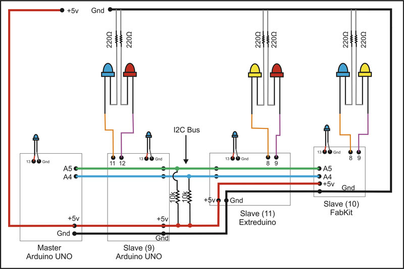
To make the task of this week I decided to use the I2C technology. I will communicate four microcontrollers, two of the Arduino UNO boards,
one Extreduino (designed in this Fab Academy 2015 by Raúl Diosdado ), and a Fabkit v0.2 ( I make one for this task).
Keep in attention a couple of considerations when making the connection, the first is for all Devices have to share Both 5V (Power) and GND (Ground). The second is that
the I2C BUS (composed of two wires, in my case all devices connecting analog connections 4 and 5 -SDA and SCL-) can not be 0v, to fix this place two pull-up resistors to 5V. The value
of these resistors can be between 1.5K and 47K, I will use 10K resistors.
Connections Schema
Once the connections are made, as I detail this demo should work.
Master (Arduino UNO board):
Send every second a consecutive value (x) from 0-5 to all devices (9,10 and 11) and also illuminates an LED (pin 13 of the board) for 100 ms in each sending data.
For all slaves devices see next tables:
Slave 1 (Arduino UNO, address 9):
Value received
Action
0
Blink 200ms LED1
1
Blink 200ms LED2
2-3
Led 13 On
5
Led 13 Off
Slave 2 (Fab Kit, address 10):
Value received
Action
2
Blink 100ms LED1
3
Blink 100ms LED2
4
Led 13 On
5
Led 13 Off
Slave 3 (Extreduino, address 11):
Value received
Action
1
Blink 50ms LED1
4
Blink 50ms LED2
2-3
Led 13 On
5
Led 13 Off
To program the devices will use Arduino IDE via USB for Arduino UNO and use FTDI for Extreduino and FabKit. the library "Wire.h"
facilitates communication via I2C through its implemented features. Although it is repetitive, then I show the programming code for all devices:
Slave 1 (Arduino UNO)
Slave 2 (FabKit)
#include <Wire.h>
#define LED_PIN 13
#define LED_1 12
#define LED_2 11
int x;
void setup() {
Wire.begin(9); // Start I2C Bus as a Slave (Device Number 9)
Wire.onReceive(receiveEvent); // register event
pinMode(LED_PIN, OUTPUT);
pinMode(LED_1, OUTPUT);
pinMode(LED_2, OUTPUT);
x = 0;
}
void loop() {
//If value received is 2 blink LED 1
if (x == 2) {
digitalWrite(LED_1, HIGH);
delay(100);
digitalWrite(LED_1, LOW);
delay(100);
}
//If value received is 3 blink LED 2
if (x == 3) {
digitalWrite(LED_2, HIGH);
delay(100);
digitalWrite(LED_2, LOW);
delay(100);
}
if (x== 4) {
digitalWrite (LED_PIN, HIGH);
}
if (x == 5){
digitalWrite (LED_PIN, LOW);
}
}
void receiveEvent(int howMany) {
x = Wire.read(); // receive byte as an integer
}
Slave 3 (Extreduino)
MASTER (Arduino UNO)
#include <Wire.h>
#define LED_PIN 13
#define LED_1 8
#define LED_2 9
int x;
void setup() {
Wire.begin(11); // Start I2C Bus as a Slave (Device Number 11)
Wire.onReceive(receiveEvent); // register event
pinMode(LED_PIN, OUTPUT);
pinMode(LED_1, OUTPUT);
pinMode(LED_2, OUTPUT);
x = 0;
}
void loop() {
//If value received is 1 blink LED 1
if (x == 1) {
digitalWrite(LED_1, HIGH);
delay(50);
digitalWrite(LED_1, LOW);
delay(50);
}
//If value received is 4 blink LED 2
if (x == 4) {
digitalWrite(LED_2, HIGH);
delay(50);
digitalWrite(LED_2, LOW);
delay(50);
}
if ( (x ==2) || (x==3) ){
digitalWrite (LED_PIN, HIGH);
}
if (x == 5){
digitalWrite (LED_PIN, LOW);
}
}
void receiveEvent(int howMany) {
x = Wire.read(); // receive byte as an integer
}
#include <Wire.h>
#define LED_PIN 13
byte x = 0;
void setup()
{
Wire.begin(); // Start I2C Bus as Master
pinMode(LED_PIN, OUTPUT);
digitalWrite(LED_PIN, LOW);
}
void loop()
{
digitalWrite (LED_PIN,HIGH);
Wire.beginTransmission(9); // transmit to device #9
Wire.write(x); // sends x
Wire.endTransmission(); // stop transmitting
Wire.beginTransmission(10); // transmit to device #10
Wire.write(x); // sends x
Wire.endTransmission(); // stop transmitting
Wire.beginTransmission(11); // transmit to device #11
Wire.write(x); // sends x
Wire.endTransmission(); // stop transmitting
delay(100);
digitalWrite(LED_PIN,LOW);
x++;
if (x > 5) x=0;
delay(900);
}
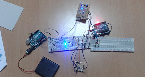
Everything is ready to make connections and get it going, I've ridden all over a couple of breadboard with recycled components. The result was expected,
the master board correctly sends the data through the I2C bus and all slave devices correctly made orders received parameters.
(*) Drivers needed for FTDI connection can find them in the task of week 10 (Input Devices)
 Week 13:: Networking and Communications