Final Project
Assignments:
complete your final project
Note: all final files to the bottom of the page
0. Introduction
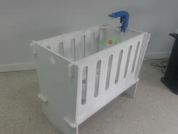
For my final project I decided to make a smart baby cot. It is a cradle of furniture that incorporates a small
children's toy figures as a rotating carousel, this toy also includes a small web camera that allows you to observe
the baby. All of these features (and future functionality that can be added easily) are controlled through a web page,
accessible locally, from any device connected to the network and allow the use of web browser. This is possible to do
with a Raspberry Pi (integrated in the children's toy) that acts as a web server (Apache) and can communicate through
a FabKit FTDI to perform different actions.
I chose this project because it matches the birth of my son with the completion of Fab Academy (July) and I thought I
would make something for him. It is a completely open to collaboration project (I can do better by future contributions
of different communities).
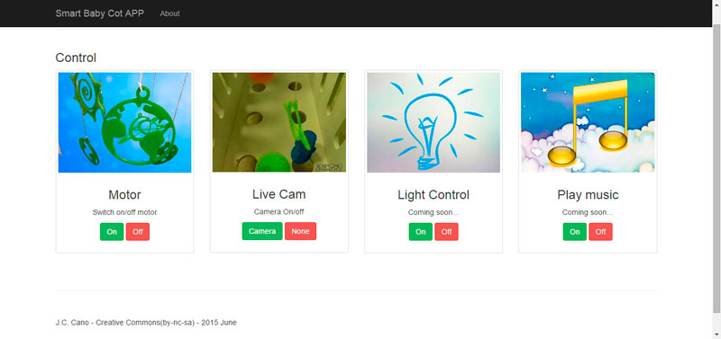
Currently, from the "web app" that controls this crib can turn on or off the motor that moves the figures, I
can also turn on or off the webcam that gives me real-time images. The web app is preinstalled with two functions:
control of lights and music or sound control.
This project has great potential for expansion: temperature or humidity sensors, microphone, balancer, alerts of different
types (temperature, sound, ...) and many more that will surely contribute to people interested in replicating and improve
the intelligent baby cradle .
Another feature is that it can become a small sofa simply by removing one side of the cabinet..
I hope the makers enjoy both this project and I hope you enjoy my son.
Regards, J. C. Cano
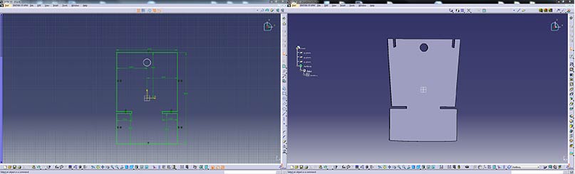
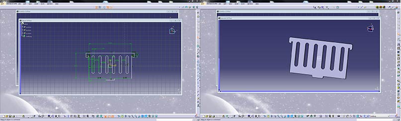
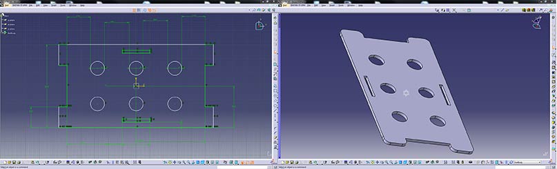
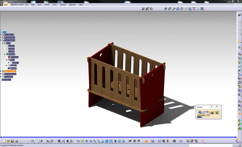
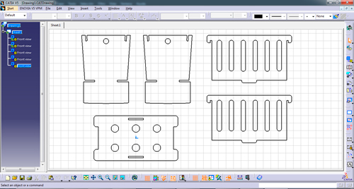
1. 3D Design
I've never done 3D design, thanks to Raul Diosdado for giving me some quick lessons on Catia. This program has a short learning curve, and although I do not know even 1% of its possibilities, has enabled me to design baby cot quite accurately. I had to make some changes to the original design that I made in Corel Draw, Catia has allowed me to observe in detail how to assemble the parts.
Files (All the necessary files are available in the download section):
- For milling machine (.dxf format):
- Front: front.dxf
- Lateral: lateral.dxf
- Base: base.dxf
- For 3D Printer (.stl format):
- Not defined, I need to redesign (.stl format)
- Crosstree: crux.stl
- Support: support.stl
- All files zipped: week2.zip
2. Making the crib furniture
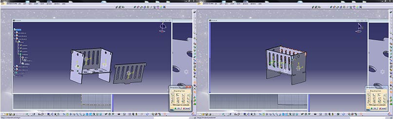
In previous weeks I make an model of the baby crib using 3d printer which has allowed me to correct design flaws when making the final model. On Catia I have corrected some bugs, especially in the parts assembled. Then I generated the .stl files required for use with other program: Aspire.
Catia: corrected some bugs
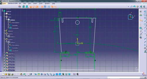
Catia: Preparing .stl´s
Before loading the files in Aspire I measured the thickness of the material that will be used in the milling machine is DM 19.3 mm. Now I have the information needed to create the files you need milling machine.
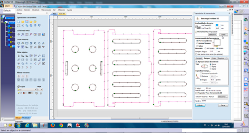
Aspire: inner cutting strategy
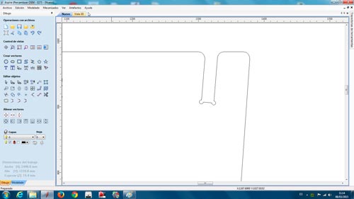
Aspire: outer cutting strategy
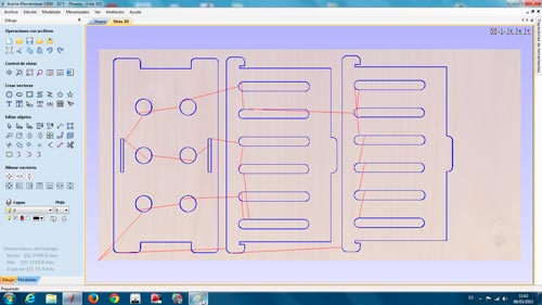
Prepare the Aspire software measures DM board (122mmx244mm) and begin to place the various parts of the crib I'm going to be milled. For inner sockets I need to do some drilling 6mm (I'll use a milling cutter 6mm) in the corners of assemblies: First ruling that would later discover, when the cutter is 6mm, the hole should be higher for the milling machine what do (need sanding assemblages). I took advantage Aspire to perform some chamfer to round the corners. After I designed cutting strategies, exterior and interior, with a milling cutter 6mm in both cases and making an input ramp (30º) for the milling cutter.
Aditional configuration for 6mm tool:
- Step: 2.4mm
- Screw speed: 18.000 rpm
- Feed rate: 2.000 mm/min
- Descent speed: 400 mm/min
Aspire: inner cutting strategy
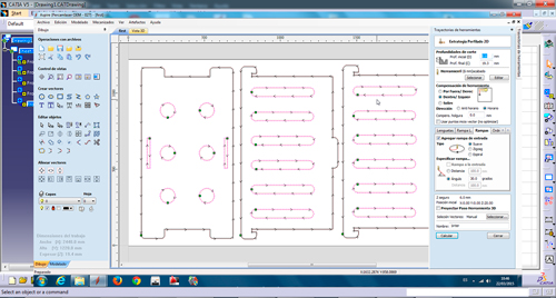
Aspire: outer cutting strategy
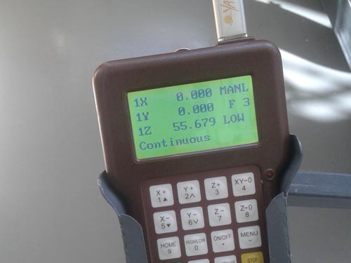
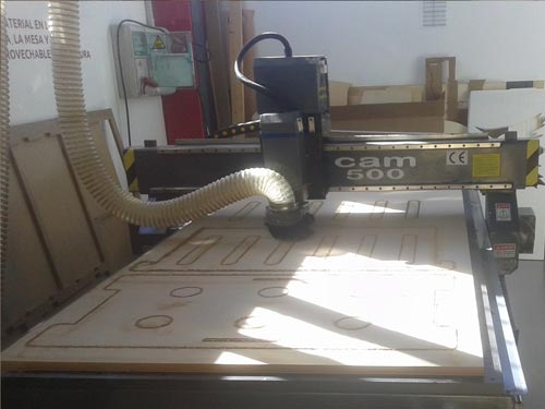
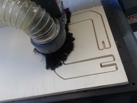
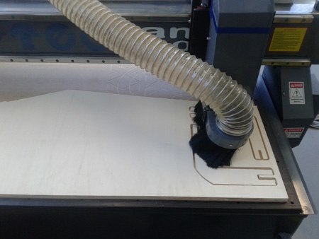
Prepare the milling machine, turn on the suction and calibrate with the measurements the thickness of MDF board, establish a home and prepare the first job, start with the inner cutting strategy.
Milling machine: Doing home
Milling machine: inner cutting
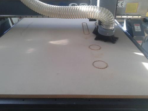
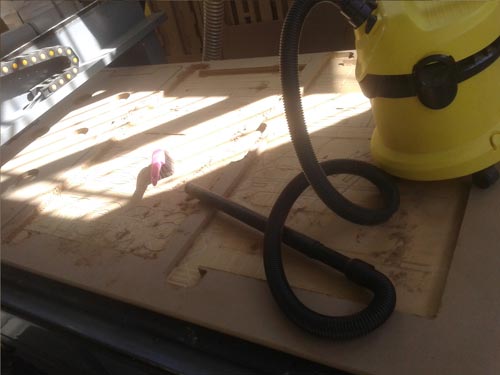
Once the milling machine is finished with inner cutting strategy, sending the second part of the work to be performed outside cuts, before I make a little vacuuming.
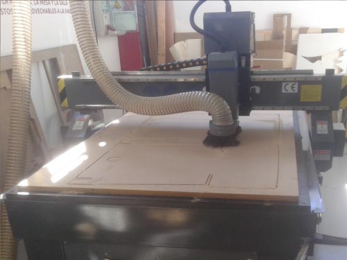
Milling machine: outer cutting
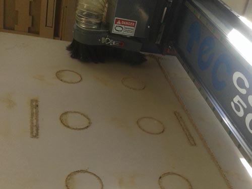
Milling machine: outer cutting
Upon completion of the first three parts (two sides and base of the cradle baby), clean everything and take back what's left of the board. I put a new board and repeat the above steps to recalibrate the machine (working with DM there may be small thickness differences). It's Time to cut the two parties to be the header of the baby crib. Repeat the above operation using two cutting strategies, one inside and the other outer.
Milling machine: Cleaning
Milling machine: Cutting headers of the baby crib
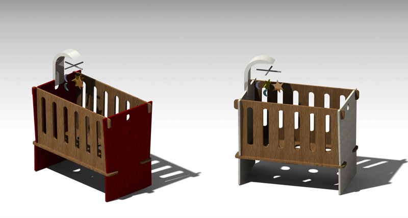
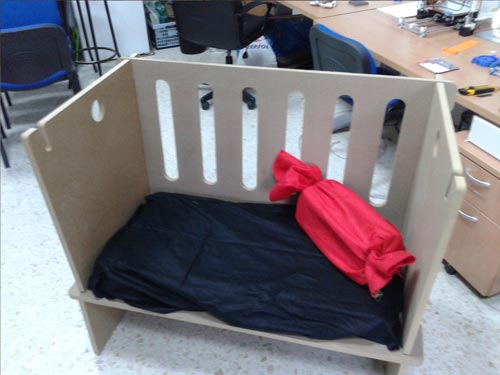
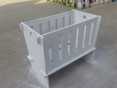
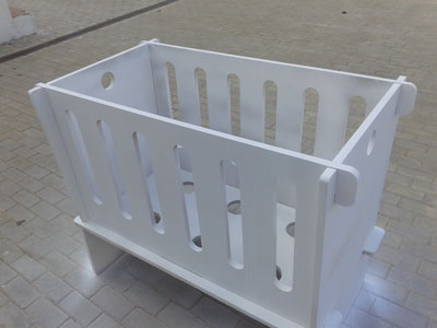
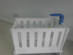
It was time to mount the cradle baby and record defects for an improved version. I can transform the baby crib into a small sofa, you can see in the last image
Baby Crib: Assembling the baby crib
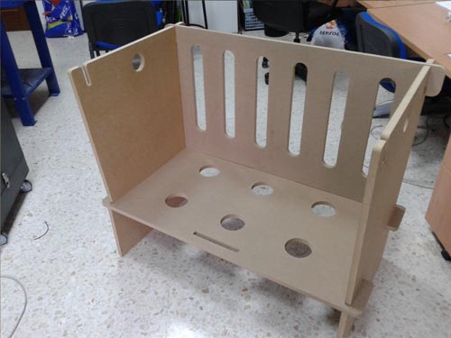
Baby Crib I
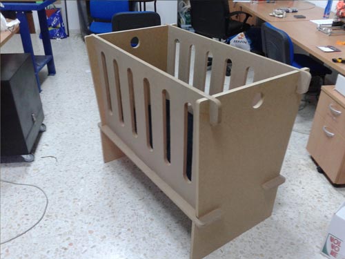
Baby Crib II
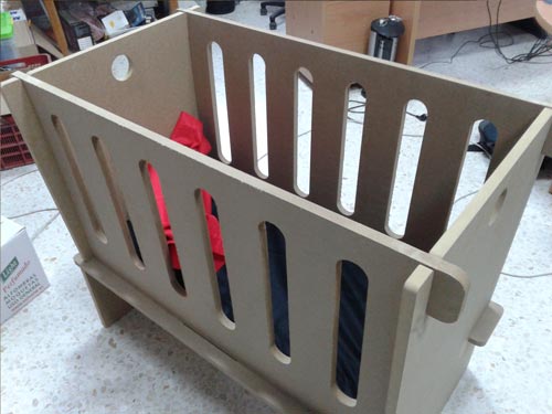
Baby Crib: Transforming into a small sofa
Faults:
- The pieces need to fit too much force.
- Maybe the crib is too deep and not be comfortable taking the baby.
- I need to create holes engaging portions with a larger diameter.
- The material used, DM, is too heavy and unattractive.
Milling Machine: Baby Crib from Carlos Cano on Vimeo.
Files (All the necessary files are available in the download section):
3. making child toy Support
The next step was making the toy child support and all the electronics that make up this project. I have designed a piece at an angle of 90° which engages the wall of the cradle on one side and the other with another small piece (like a small ping pong racket) holding the entire structure and contains support for le motor.
Support:
Support:
The first design I needed to create two identical pieces, I cut with CNC milling, the material is 19mm plywood.
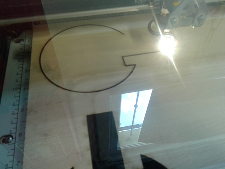
The small support I have cut directly into the laser cutter using 16mm plywood.
All these elements fit together (press-fit)
Laser cut:
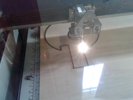
Laser cut:
Once all the pieces are performed cut a hole using a drill and a Crown Drill. Finally I paint these three elements blue.
Drill:
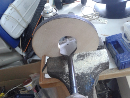
Paint:
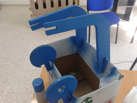
And finally, paint the cot with white
Painting:
Painting:
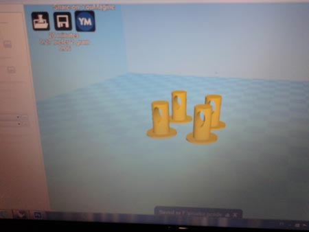
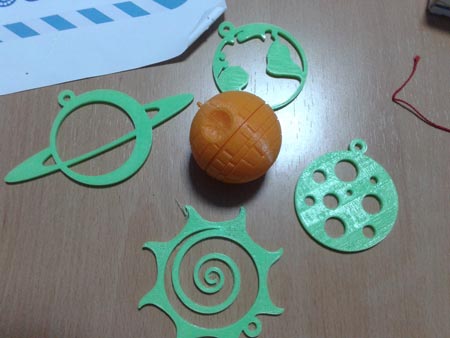
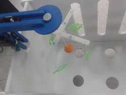
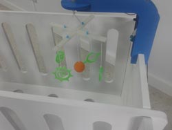
4. Printing (3D) pieces of child toy
well, though I include the designs I did for this child's toy, for final assembly I preferred to use some
models found in Thingiverse are objects in space and a small death star (start Wars) in the center.
To hang all these elements I designed and printed a crosspiece I've subsequently perforated at some points with the help of a small drill.
All material used is PLA (green, orange, white and blue), and use 230º for the temperature of 3D printer. The designs included in the download section, and some links that I printed:
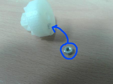
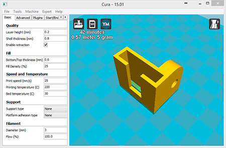
I have also modified a piece of the extruder Prusa I3 to fit the step motor, reducing him shaft hole and adding
a small ring to hang the crosspiece.
All downloads are available at end of this webpage, in download section.
shaft coupler:
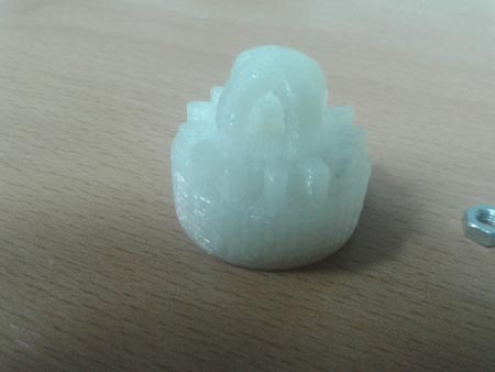
shaft coupler:
crosspiece:
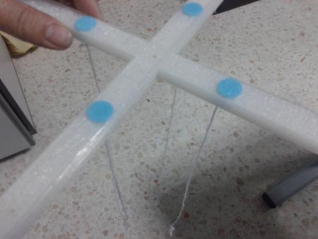
plugs crosspiece:
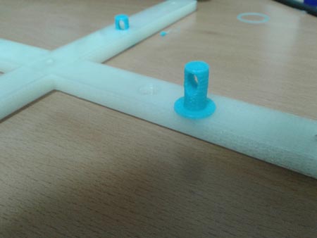
crosspiece:
elements:
PiCam Support:
Children toy:
5. Electronics used
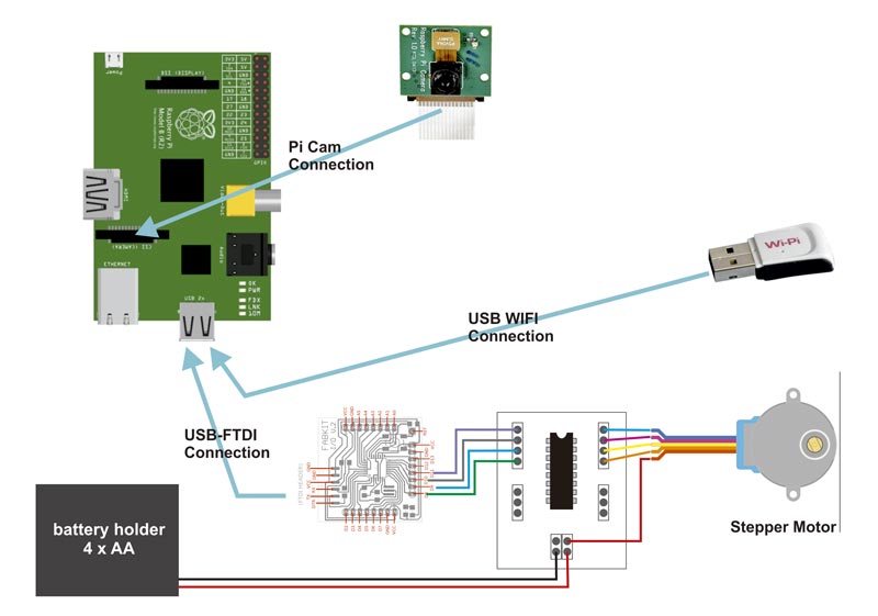
The electronics required for my project is: - 1 x Raspberry Pi (including PICAM and wifiPi) - 1 x FabKit 0.3 (original design) see instructions - 1 x Driver Step motor (Redesigned) To control the cradleI have thought of using a Raspberry Pi to mount a web server on it to perform the functions of communication interface with Fabkit. Communication between the Raspberry Pi and Fabkit is made by FTDI connection and driver stepper motor is connected to Fabkit on pins 8, 9, 10 and 11. This step motor controller has 3 free tickets to use in extensions of the project (eg control lights). In subsequent steps I explain how to configure Raspberry Pi to perform communication correctly.
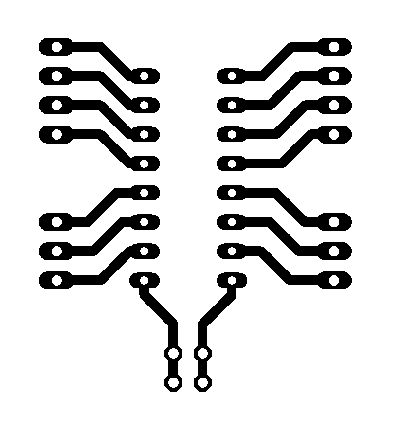
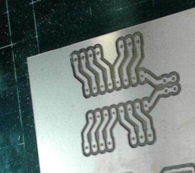
To make the driver motor is only necessary milling board, a ULN2003A chip and some headpins. Files needed for its realization are attached in the download area
border:

Tracks:
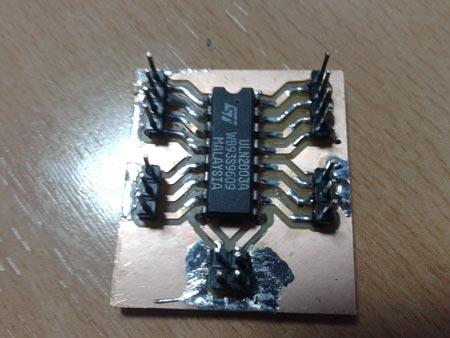
Drilling stepper motor driver:
Stepper Motor Driver
There is a problem At power the engine with the energy of the raspberry pi, and the Raspbian system crashes. To resolve this situation I used a battery holder for stepper motor power, cutting power with other devices.
6. Connections
7. Raspbian: preparing the OS
It is time to prepare the operating system for the Raspberry Pi, I decided to install Raspbian, one of the most widely used distributions
with Raspberry Pi. Mainly I need to install this operating system the following services / applications:
- Web server with PHP support (Apache)
- Python 2.7 (installed by default)
- Piserial (required for communication with FABKiT via FTDI)
- Drivers for PICAM (installed by default, you just have to activate)
To begin, you need the image Raspbian, can obtain a copy of the latest stable version at the following link:
http://downloads.raspberrypi.org/raspbian_latest
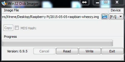
Once downloaded, we need to spend our SD card image (in my case I used a SD card 8 GB, Class 10). This step can be done from Windows,
Linux or Mac, I will use Windows 7, for which download the application need further Win32DiskImager
(http://sourceforge.net/projects/win32diskimager/). When downloaded this application, unzip the file (for example on the desktop)
and run the application as administrator. With the SD card inserted into your PC and select the downloaded image Raspbian we
click on the write option and wait for our SD card is ready.
Insert the SD card into the Raspberry Pi, and connect a monitor with HDMI connection, a USB keyboard, WIFI (WIPI) device and the power
through the microUSB port.We observe that the operating system begins to load and will wait for that we insert username and password,
by default this installation the user is "pi" and the password "raspberry".
The first thing I will do is set up your wireless device to work remotely (SSH) and in this way to disconnect the monitor and
USB keyboard.
Run the following command:
sudo nano /etc/network/interfaces
auto lo
iface lo inet loopback
#auto eth0
iface eth0 inet static
address 192.168.0.170
netmask 255.255.255.0
gateway 192.168.0.1
auto wlan0
allow-hotplug wlan0
iface wlan0 inet static
address 192.168.0.171
netmask 255.255.255.0
gateway 192.168.0.1
wpa-ssid "A_Digital2"
wpa-psk "password"
For this configuration, you must know the SSID and password of your WIFI. From this point we can work remotely with our Raspberry Pi using any SSH client, I use windows "Putty". Let's start with the installation of required packages first console execute :
sudo apt-get update
sudo apt-get upgrade
...to have updated repositories commands. Then I will install the web server that I will use for the main app. Run in a terminal: "sudo apt-get install apache2 php5 libapache2-mod-php5" restart the service with the command:
sudo /etc/init.d/apache2 restart
From this moment on we can access with a browser to the IP address (which we have previously configured) through a browser. This version of Raspbian have already installed Python packages, we will install additional packages needed Python (if necessary):
sudo apt-get install python-picamera
sudo apt-get install python-pipsudo apt-get install python-serial
To work in a more simple way I'll add permissions to apache, to edit the files needed no permission problems (not recommended for production environments):
sudo groupadd www-data
sudo usermod -a -G www-data www-data
I need some services or scripts run at startup, are these three:
cotdaemon (test.py run the script as a service, is responsible for communication between Raspberry Pi and Fabkit through the serial port)
cameradaemon (starts the stream of the camera)
picamdrv (charging drivers of the camera)
Each of these scripts are created in the /etc/init.d folder to enlist the services you need to run:
sudo update-rc.d cameradaemon defaults
sudo update-rc.d picamdrv defaults
sudo update-rc.d cotdaemon defaults
Remember: You can change basic settings of the operating system running:
sudo raspi-config
From this script we can quickly estgablecer language, keyboard, camera, boot mode ...
8. Web programming
The next step is to create a folder to host the web, I have created with the following command:
sudo mkdir /var/www/cotapp
I will use bootstrap to create the web, specifically a named template Heroic Features that can be downloaded at: http://startbootstrap.com/template-overviews/heroic-features/ in the design of the web, all you've had to change is the index.html file and create some images for displaying each of the features of the crib.
In the download section you can download the complete design of the website, including images and scripts. The next thing I need is to communicate with Arduino, to make've thought about calling a PHP script (which is stored in the root directory of the web application) each time you press one of the buttons control the web, this PHP script set a connection through a socket with another Python script (executed at startup as a service) and send to this a number that identifies the button pressed. PHP Script code action.php:
<?php
$msg=$_REQUEST['msg'];
$socket = socket_create(AF_INET, SOCK_STREAM, SOL_TCP);
$result = socket_connect($socket, "localhost", 7070);
$msg_send=$msg."\n";
socket_write($socket,$msg_send);
socket_close($socket);
?>
The other key Script for this application is made in Python and is responsible for passing the code to the button pressed fabKit through the serial port to create the serial connection need to know the name of your device (Arduino, fabkit, etc ,. .) in my case it is ttyUSB0. The following Python code shows how to create a listening port to receive information from PHP script, how to create a serial connection to our fabkit and send the pressed button code:
import socket
import sys
import serial #Instalar pySerial con pip si no esta instalado.
import os
arduino=serial.Serial("/dev/ttyUSB0",9600) #Enlazamos con el arduino a 9600 bau$
HOST = '127.0.0.1' # Symbolic name, meaning all available interfaces
PORT = 7070 # Arbitrary non-privileged port
s = socket.socket(socket.AF_INET, socket.SOCK_STREAM)
s.setsockopt(socket.SOL_SOCKET, socket.SO_REUSEADDR, 1)
print 'Socket created'
#Bind socket to local host and port
try:
s.bind((HOST, PORT))
except socket.error as msg:
print 'Bind failed. Error Code : ' + str(msg[0]) + ' Message ' + msg[1]
sys.exit()
print 'Socket bind complete'
#Start listening on socket
s.listen(10)
print 'Socket now listening'
#now keep talking with the client
while 1:
#wait to accept a connection - blocking call
conn, addr = s.accept()
cadena=conn.recv(1)
print 'cadena recibida: ' + cadena
print 'Connected with ' + addr[0] + ':' + str(addr[1])
if cadena=='1':
print 'envio 1 '
arduino.write('1')
elif cadena =='0':
arduino.write('0')
elif cadena=='4':
os.system('nohup sudo service picamdrv stop &')
elif cadena=='3':
os.system('nohup sudo service picamdrv start &')
s.close()
A small detail of this script, when we turn on or turn off the camera with the buttons on the web, we stop or start the service picamdrv with the lines: "os.system ('sudo nohup stop service picamdrv &')" and "os.system ('sudo service picamdrv nohup start &') ". There is also an index.html Javascript embedded which is responsible of changing the existing image in the section of camera control. To make calls an asynchronous way I've included the library "jquery" (all code for this application is available in the download section).
The site includes two unimplemented features, control lights and sound control. Following the same pattern as the rest is simple to develop that part of functionality.
9. electronic programming
Since Fabkit acts as an Arduino UNO I decided to program your IDE and language, the code is simple miy provides serial communication and expects orders in the form of codes sent by the python script above. Fabkit is connected to the plate having the motor driver via pins 8, 9, 10 and 11. The motor controller board has 3 free pins that can be used to control lights for example.Stepper.h I use the library provided by Arduino to control the motor.
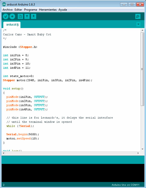
And the complete code is as follows:
#include >Stepper.h<
int in1Pin = 8;
int in2Pin = 9;
int in3Pin = 10;
int in4Pin = 11;
int state_motor=0;
Stepper motor(2048, in1Pin, in3Pin, in2Pin, in4Pin);
void setup()
{
pinMode(in1Pin, OUTPUT);
pinMode(in2Pin, OUTPUT);
pinMode(in3Pin, OUTPUT);
pinMode(in4Pin, OUTPUT);
// this line is for Leonardo's, it delays the serial interface
// until the terminal window is opened
while (!Serial);
Serial.begin(9600);
motor.setSpeed(10);
}
void loop()
{
if (Serial.available())
{
state_motor = Serial.parseInt();
}
if (state_motor==1){
motor.step(20);
}
if (state_motor==0){
// nothing, this if can be deleted
}
}
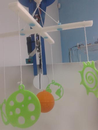
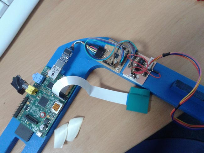
10. Final result
When everything is set and mounted promeras I perform tests, the buttons respond correctly. Following the advice of tutors / mentors I have reduced the functionality of the cradle to the motor control children's toy, we can also turn on or off the webcam when we want. The web application is ready to add two new features, control lights (which can be a LED placed on top of the child's toy) and play music or sounds (can be done with a python script). Furthermore, the project is open to new ideas (microphone, temperature, humidity, rolling, alerts, ...) Here we can see a video demonstration of the operation of the baby cot.
Final Project: Smart Baby Cot from Carlos Cano on Vimeo.
11. Files
Furniture parts:
Child toy 3D elements:
- Children toy crosspiece
- Earth (Thingiverse)
- Ligth support (to expand project )
- Saturn (Thingiverse)
- Su n(Thingiverse)
- Mercury (Thingiverse)
- Moon
- Star
- Sun
- Plugs for crosshead
- Death Star top(Thingiverse)
- Death Star botton(Thingiverse)
- Death Star trent(Thingiverse)
- Shaft coupler
- PiCam Support
Electronic parts - Stepper motor driver:
- borde PNG file
- Tracks PNG file
- Eagle file I - epf
- Eagle file II - brd
- Eagle file III - pro
- Eagle file IV - sch
Electronic parts - FabKit:
Sourde Code:
- All web files (include scripts, Bootstrap template and images)
- daemon file service
- daemon file service
- daemon file service
- Bash Script (included on all web files)
- PHP Script (included on all web files)
- Python Script (included on all web files)
Operating System:
12. Electronic equipment not manufactured