Week 10:: Input Devices
Assignments:
measure something: add a sensor to a microcontroller board that you've designed and read it
To perform the tasks in this this week I decided to use the following software:
- Photoshop CS5: For the layout and retouching of images for the web.
- Eagle To design the the board
- Fab Modules: For the modela Machine
Design and prepare
This week is interesting because it will allow me to discover input devices need my final project. The first thing I do is a sound sensor that triggers an action when the baby, for example, is crying. For a first prototype the idea is to start the engine and lights toy baby, I'll try in future versions that there is serial communication with Raspberry Pi and through the web server and a APP reaches this notification to our mobile device.
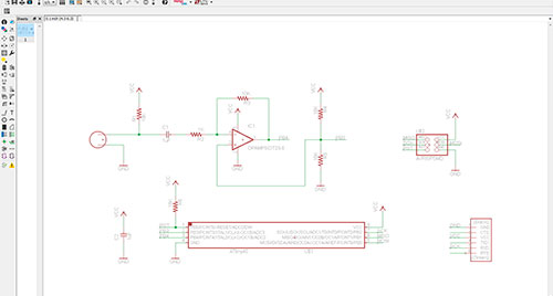
For testing I based on the template provided on the website of Fab Academy. I redesigned the circuit with Eagle and redraw the necessary tracks (Autorouter is not a good option, do it manually).
Eagle: Schematic
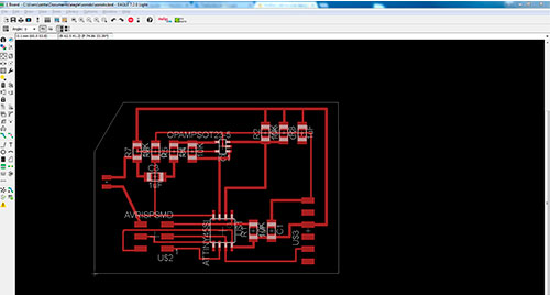
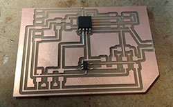
Eagle: Board
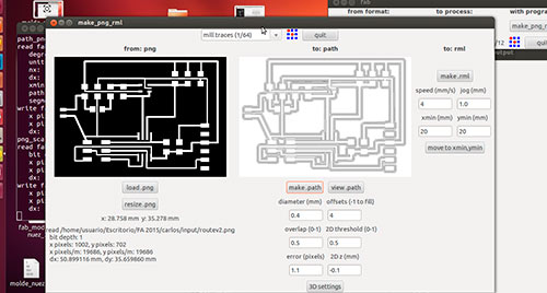
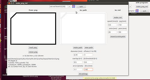
Once the design is completed, export the board file to PNG format and with the help of Photoshop center the image and generate the outside for cutting milling.
Traces
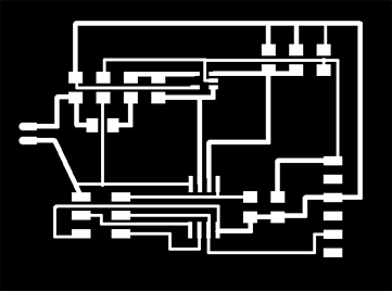
Interior

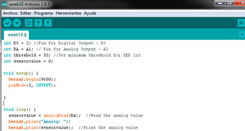
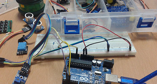
For work, this week can not go to my Fab Lab (León), this week will finish this task and will perform the task of output devices. I tried at home with Arduino kit that includes a sound sensor I have assembled is an breadboard one small project led to lighting a certain level of noise. I think the sensor is damaged, do not get variation in the sound level using the analog input A1. I'll have to wait for this weekend to complete the tests and board.
Arduino IDE: Programming
Kit Arduino: Sound sensor and more...
Sound Sensor + Arduino UNO from Carlos Cano on Vimeo.
Source Code:
int DO = 2; //Pin for Digital Output - DO
int DA = A1; // Pin for Analog Output - AO
int threshold = 53; //Set minimum threshold for LED lit
int sensorvalue = 0;
void setup() {
Serial.begin(9600);
pinMode(3, OUTPUT);
}
void loop() {
sensorvalue = analogRead(DA); //Read the analog value
Serial.print("Analog: ");
Serial.print(sensorvalue); //Print the analog value
Serial.print(" ");
Serial.print("Digital: ");
Serial.println(digitalRead(DO)); //Print the digital value
if (sensorvalue >= threshold) { //Compare analog value with threshold
digitalWrite(3, HIGH);
}
else {
digitalWrite(3, LOW);
}
}
04/21/2015 - Updated!!!
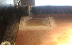
This week I performed this task with "output devices", I used the Fab Modules for tracking the .png files and send the job to the Modela machine. Then I realized solders components on on the board and everything went right.
Traces
Interior
Roland Modela:
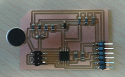
Components:
Soldering:
Sound sensor Board:
To program I used the FabISP realized at week 4 (Electronics production). First, download the files provided by the Fab Academy (Week 4 Electronics Productions) and save them in a folder from Windows (in my case) run the console (cmd .exe) and we look at the folder we created earlier. The operating system must be installed AVRDude from prompt type the following command:
make -f hello.H-bridge.44.DC.make program-usbtiny
If all it´s correct we can see on console:
C:\Users\Xtrene\Desktop\FAB Academy\Academy2015\sonido>make -f hello.mic.45.make
program-usbtiny
avr-objcopy -O ihex hello.mic.45.out hello.mic.45.c.hex;\
avr-size --mcu=attiny45 --format=avr hello.mic.45.out
AVR Memory Usage
----------------
Device: attiny45
Program: 502 bytes (12.3% Full)
(.text + .data + .bootloader)
Data: 200 bytes (78.1% Full)
(.data + .bss + .noinit)
avrdude -p t45 -P usb -c usbtiny -U flash:w:hello.mic.45.c.hex
avrdude: AVR device initialized and ready to accept instructions
Reading | ################################################## | 100% 0.04s
avrdude: Device signature = 0x1e9206
avrdude: NOTE: FLASH memory has been specified, an erase cycle will be performed
To disable this feature, specify the -D option.
avrdude: erasing chip
avrdude: reading input file "hello.mic.45.c.hex"
avrdude: input file hello.mic.45.c.hex auto detected as Intel Hex
avrdude: writing flash (502 bytes):
Writing | ################################################## | 100% 0.73s
avrdude: 502 bytes of flash written
avrdude: verifying flash memory against hello.mic.45.c.hex:
avrdude: load data flash data from input file hello.mic.45.c.hex:
avrdude: input file hello.mic.45.c.hex auto detected as Intel Hex
avrdude: input file hello.mic.45.c.hex contains 502 bytes
avrdude: reading on-chip flash data:
Reading | ################################################## | 100% 0.46s
avrdude: verifying ...
avrdude: 502 bytes of flash verified
avrdude: safemode: Fuses OK
avrdude done. Thank you.
To run the python script you must have the python interpreter installed on your PC. For Windows 7 64 bits I installed the version 2.7.9 for 32-bit (there PySerial trouble installing libraries in the 64-bit version), you can do so from this linkYou need to add the installation path to python environment variables. The easier way to set the path in python is : click start> My Computer >Properties > Advanced System Settings > Environment Variables >
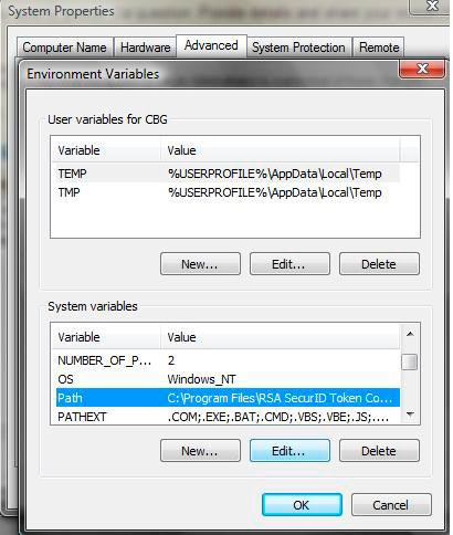
second windows > select Path > Edit > and then add ";C:\Python27\;C:\Python27\Scripts\"
Then download and install the PySerial library (necessary for communication of our board and the computer via FTDI), you can donwload in this link. Finally you need to install the FTDI drivers to communicate with the sound sensor (you can use this link or the software provided by the manufacturer of your FTDI cable). Now that I have everything installed and configured all I have to do is run the script, for this I use the command line, from the folder that contains the script write the following command:
python hello.mic.45.py
If all goes well a graphical window above shows the waveform of the sound signal collected by the sound sensor appears.
Fab Academy - Testing Sound Sensor (Thanks Nuria for the voice) :) from Carlos Cano on Vimeo.
Files: