
Assignment: write an application that interfaces with an input &/or output device
Tickling with a microphone
I think what I learned from last week is to start small small small. And then build step by step. So I'm going to live by that motto for this week, at least. I will start with the echo hello world board with a tact switch and an LED and connect it to Processing to create a graphical output interface that does something when you press the switch. Once that's done: bonus material:
I used the board from week 6, electronics design and week 7, embedded programming for this. Find the schematic and board layout there.
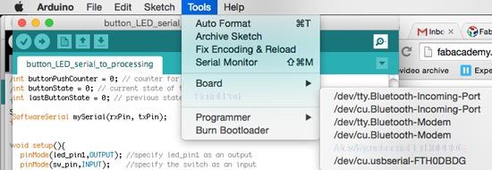
I looked up the working sketches for the echo hello world, hooked it all up. The serial communication was all garbled. But it was fixed by burning the bootloader again.
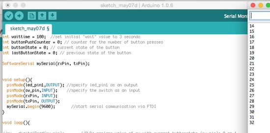
I looked up some stuff in the Processing handbook an the Programming Interactivity book to remind myself again about the interfacing between Arduino and Processing, the syntax of the latter and using the serial. They come with really good simple examples in the IDE that I combined with my own sketch that is setup to talk to the AVR chip (Attiny44).
Ok so that all works, now let's see if I can get processing to listen to serial communication coming from the ATTiny. Here: basic Arduino code to setup serial
That worked! But initially the rectangle stayed gray and doesn't go back to black so I tweaked some if loops and now have this! Beautiful, no? haha
Arduino code without a counter (incl LED blink)
Arduino code with a counter (incl LED blink)
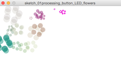
Playing around with examples was really fun, I tried getting some other examples to work with the switch and modify them to do something different, like this flower sketch I found on the Processing website. It draws a flower each time you press the switch on the board. The mouseX and mouseY position controls where you draw the flower on the canvas. The mouse values also generate different colors and opacity for each flower. I had to change the arduino code again back to sending 0 or 1 values (because it was still adding buttonpressed to a counter).
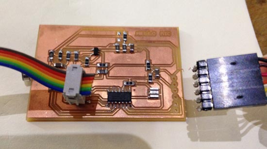
I used the board from week 10, input devices for this. Find the schematic and board layout there.. The board gives values, but they're not exactly clean and I'm not sure how optimal it is as a sensor at the moment. But there's values and I can play around with them so here goes:
I started setting up the mic board from the input devices week to also interface it with Processing. But pretty much the first thing I did was accidentally rip off the traces from the FTDI connection. Crap, I really wanted to work with analog input because it's more interesting than on/off.
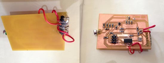
Rather than making a new board, I fixed this one with lots of hotglue and some jumpers. OK! Let's go. First thing I ran into was that the serial was giving me garbled crap. boards with a resonator = bootloader 20mHz! I forgot and had it at 8. No wonder it didn't want to talk
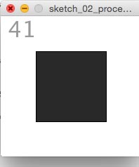
Then I changed the rectangle processing sketch so that the lightness of the gray responds to the values being sent in the serial. The higher, the lighter. But at first I only saw a flickering and very little changes. So I mapped the values coming in between 0-255 (max gray value range) to get stronger differences. This returned an error saying you can't turn a float into an int...Hmm ok. Yes Frank! Thanks! Of course, mapping values will break the integers, but easily fixed in syntaxis: val = (int)map (val, 0, 80, 0, 255); problem solved.
Well, error solved. Now I got heavy flickering. I want to see what values it's taking so I'm going to find a way to display the values as text in the processing window. Hmm It's giving 31 and 141 alternating by the looks of it. Which is weird because checking in the arduino serial port, if I don't blow in the mic it gives only 0s.... Hmmm hmm hmmm what is going on!
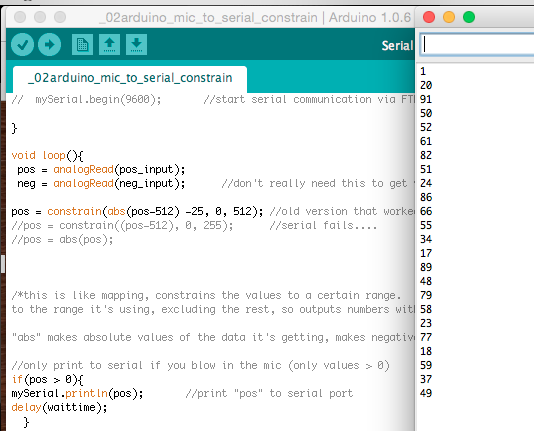
I double triple checked and the values in Arduino's serial look really different than what processing is giving back to me. To make it a bit easier I changed the Arduino code to send only data when values are more than 0 (when someone is blowing in the microphone. I can use it as an on/off switch this way, but you kind of want something else when you're working with an analog input. This image shows the values of blowing into it once:
Finally I found out that, the values in Arduino are in ASCII, and they're converted to decimals in Arduino (Thanks, Frank!). So a value like 38, which should be within the range that I constrained, when converted from ASCII to decimal is all of a sudden 5156, which is filtered out of the range. The only 3 values that accidentally fall within the range were being displayed.
But you can still do a lot of fun stuff with it, like this Tickle example from processing.org. Processing code Tickle
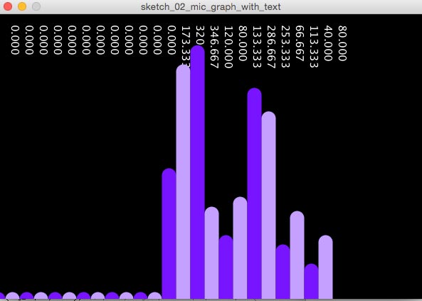
Finally I made a bit of a more "serious" graph. It's a modified version of the (quite often used looking at documentation of people) of the graph tutorial on the Processing website. I made the purple colors alternate, made the bars wider and added vertical text to discplay the values on top.
This is the code for Processing, as well as the Arduino code for the graph sketch (it's slightly different: the interface only works with values constantly coming in, so I had to change the arduino code to send values also when they're 0 - before I was using code that only sends if val > 0.
So maybe this is technically an output device. But it's also a little bit like a second screen right? So that makes it an interface? I don't know. But anyway, I'm putting it here as a bonus.
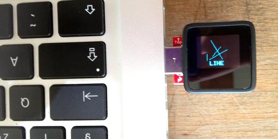
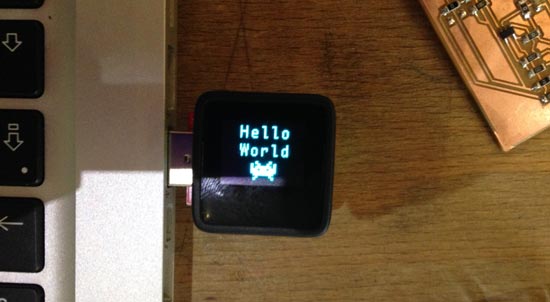
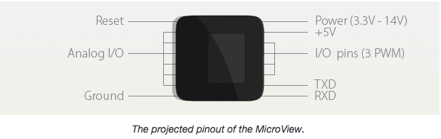
OK, my analog input is stalled for a bit until I fix that board. So first I'll see if I can get the Microview up and running instead. I started on their getting started page. I have the chip and the programmer so I could start right off. It's recommended to start with online code editor Codebender because it has all the appropriate libraries built-in. But you can also do it with Arduino. I installed the chrome plugin and the FTDI drivers. Wow this is really userfriendly. And there we are hello world, all good to go!
After installing the Microview and Time library to the Arduino IDE I also had a blink sketch running in the local Arduino IDE, which I like better than this online thing. Here's to two libs you need to install.
In order to upload to the Microview you need to select Uno as a board (the behave the same way.
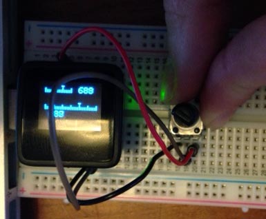
OK so installing is a breeze. Let's see what else I can do with this, like using it as an output device. I looked at the examples and had the stuff at hand to make a quick potentiometer circuit (this is the example code. Looks like this!
Cool. Now I guess what would be interesting is if I can set up communication between the button board and the microview. Hmmm. Let's see. Well the serial line would be competing for attention if I plugin two boards so that won't work. How about I2C? If found some resources here.
And it looked like other people were thinking the same thing (see comments section). So looks like the Wire lib is supported.

That's a good start but after some research it looks like it will be pretty difficult to interface my ATTiny45 master board from last week (with the TinyWireM library) with a WireS library that is supported on the Microview/Uno.
Datasheet says: SDA is on pin A4, SCL on pin A5, GND is next to A0 and VCC is 5V marked on the board. For UNO it's thesame
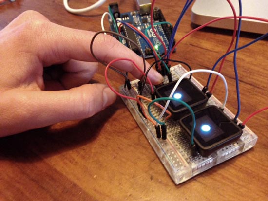
Ok let's hook these babies up! First I used the simple Master/Slave examples that come with the Wire libraries. What I changed: the master doesn't send out a string but a 0 or a 1 alternating with each loop. And instead of printing to the serial port, I let the Microview (slave), display a blink. That worked pretty quickly!
Then I set up an interaction with a pushbutton. I wired everything up and rewrote the sketches, now so that the master sends out a 0 or a 1 depending on whether the button is pressed, the slave responds by displaying a ball on the OLED display. CHECK! That was fun, now I'm able to use the Microview in projects using Atmel's ATmega 328 chip (supports the Wire lib).
Code:
OK while I'm at it why not just do two..... :D (just upload same slavecode to second microview and wire SDA/SCL/5V/GND together.