get an FTDI-USB cable and download drivers here and also here I have a 64bit processor (apparently :), and installed the use the 10.4 one in the setup as recommended by Emma). Also download this file (this is all mentioned in the tutorials too). I got stuck around §3.2 and found that I had to use a sudo command to go through where terminal fed back permission denied. as explained here
Just copying the commands didn't work becausethe path to the files was different on my machine. But giving the command "cd" and then dragging the folder location into command line fixed that.
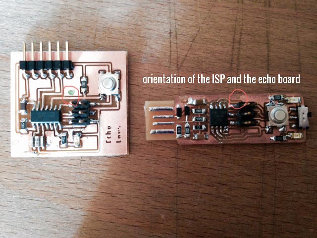
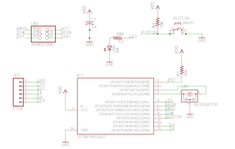
I had to find the 1 pin on my 6pin header. I had to check the orientation of the Attiny (dot on component), and look in the schematic to find the MISO pin, which links to pin 1 of the six pin header. I made a green dot on the board so I remember next time what the orientation is
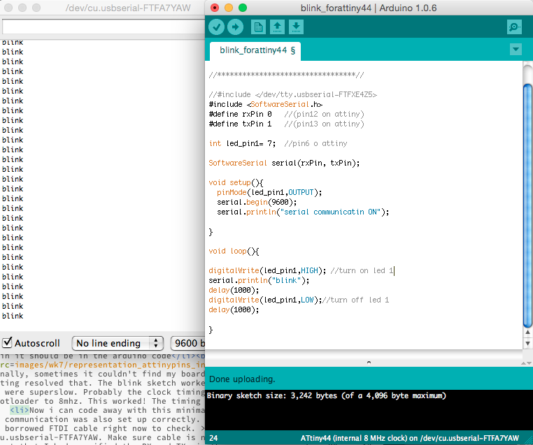
Running a simple Blink sketch, with serial communication in Arduino IDE
I installed the ATTiny board files to the Arduino environment as explained in the High-Low tech tutorial and selected the ATtiny 44 with 20mhz clock as I am yet to burn the bootloader. You burn this into the chip to make the 20hz clock an 8 hz clock (necessary for the serial communication via FTDI there were problems with this, bootloader should be burned to 20MHz, see below.
Go to > Tools > Programmer to select the FabISP as your In System Programmer. USBtinyISP is equal to the FabISP
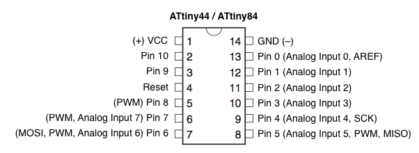
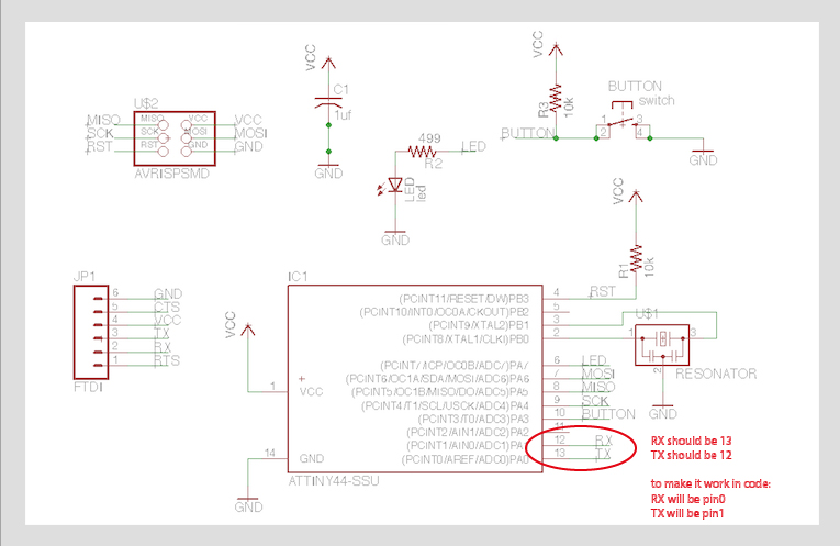
I tried running the blink sketch, and looked at my schematic to translate the right pin numbers into pin numbers for in the code: my LED pin is pin 6 on the ATtiny, which equals to pin 1 in the Arduino code, see pic below.
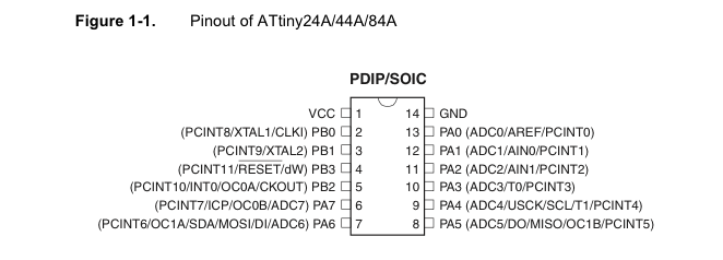
pins of the ATTiny have different names in the schematic and in the codes. Look at other peoples documentation to see the translation numbers of the pins, eg. this from emma's site. The datasheet (under PDIP/SOIC) won't tell you what pin it should be in the arduino code
Representation of attiny44 pins to use in Arduino code
finally, sometimes it couldn't find my board. But some unplugging and restarting resolved that. The blink sketch worked but the timing was all off, the blinks were superslow. Probably the clock timing was off so Emma suggested to burn the bootloader to 8mhz (should be 20MHz!). This worked! The timing was resolved.
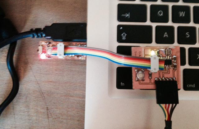
Now i can code away with this minimal board. But first I made sure the serial communication was also set up correctly. Great for debugging later and I have a borrowed FTDI cable right now to check. > Tools > Serial Port > /dev/cu.usbserial-FTFA7YAW. Make sure cable is not connected upside down....Below is a pic of how they should be connected
I found out that I had specified the RX and TX pin the wrong way around....RX was 12 on IC, so 1 in code. TX is 13 on IC, so 0 in code. But this didn't work, I got no feedback in the serial communication. When I switched them: RX =0 and TX = 1, it worked....See sketch below
So finally I double checked because this didn't seem to add up with the representation of the attiny pins as described in the visual above. It turned out that I (and many other people probably) have made a mistake in the schematic. It's easy to work around just by changing the numbers in the code, but I'm still documenting it here for future reference.
Basics of an Arduino Blink sketch for ATtiny & Other reference:
void setup() and void loop()
working with the LED : say that your LED is connected to pin 8: on top of sketch, before void setup(): write int led_pin_1 = 8;
in void setup: say that the led pin is an output pinMode(led_pin_1, OUTPUT);
in void loop: say what the LED should do when: digitalwrite(led_pin_1, HIGH); turns it on. Digitalwrite knows only HIGH and LOW (on/off). Then delay it with one second: delay(1000);. Then again, set it to LOW, delay, end loop: the light is blinking.
analogWrite(); you can use that to control the intensity of the light, you can use it with pin 8 because it has PWM, Pulse Width Modulation. The range is 0-255. Like this: analogWrite(led_pin_1,255); you can only use analogWrite on a PWM pin!
Using the switch: look up the reference pin for your code.
use digitalRead: create int for your switch pin, and create int sw= 0; to store values. Then in void setup: pinMode(sw-pin, INPUT); and in voidloop: sw = digitalRead(sw_pin); Now it's storing the values, but not doing anything with it. digitalRead is either HIGH or LOW
using the analogRead: use it to read continuous values (not just high or low. You can use this command only if the hardware pin is also an anolog input. analogRead ranges from 0-1023.
voltage on the board =5V when connected to a computer
MOSI and MISO pins are used for serial communication. VCC and GND pins are only used for VCC and GND. The other pins can all read digitalRead and digitalWrite, and some can do more, like PWM for analogWrite and analog inputs for analogRead
Programming the board to do 'something': Arduino IDE
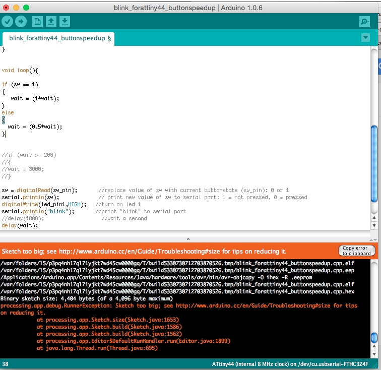
I started playing in the Arduino IDE because I'm a bit familiar. I noticed pretty quickly that a 4kB sketch is very small and you easily reach the limits. I tried using a float in one of the setups for example. That didn't work...I immediately got errors that it became too big:
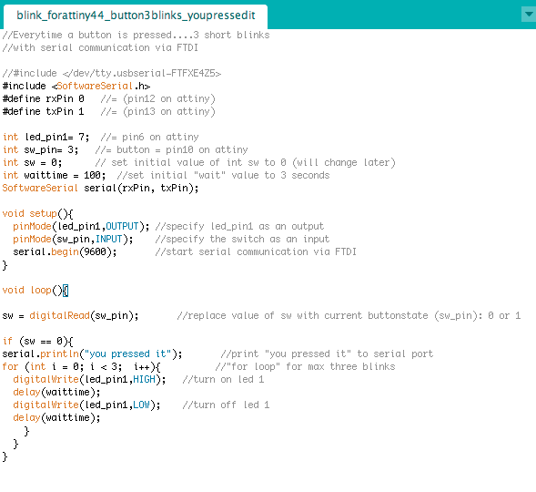
Finally I wrote a sketch that makes the LED blink 3 times and say to the serial port : "you pressed it". Here's the sketch, and a video to demonstrate.
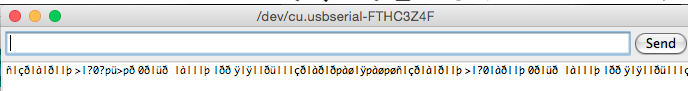
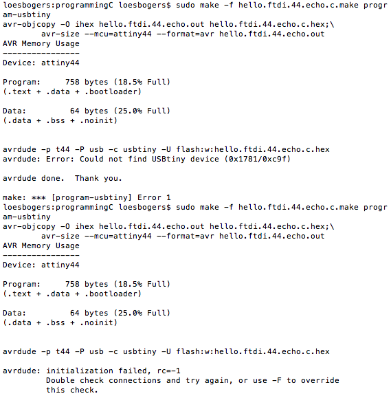
Then I took a shot at C. I started out by using Neil's sketch and trying to run it on the board. I followed this tutorial from fablab Providence to do it. First thing that went funny was when I tried getting the first echo from the board and I got this string of odd characters....
the baud rate of the Arduino IDE serial monitor was set to 155200 as mentioned, but I didn't burn the bootloader to 20MHz using the sudo steps in the tutorial (I had - what turned out later: wrongly - burned the bootloader to 8 MHz when using the Arduino IDE). But since this wasn't working I burned it to 20MHz now. And tried to run the make command again. But it kept giving me this "avrdude: Error: Could not find USBtiny device (0x1781/0xc9f)". Aaarrrrgggg. Fiddling with the connection didn't help.
And also Arduino couldn't see the board anymore, not as a 20mhz, and not as a 8 mhz board. Uh oh....I think I broke it...
Arduino: 1.0.6 (Mac OS X), Board: "ATtiny44 (internal 8 MHz clock)"
avrdude: initialization failed, rc=-1
Double check connections and try again, or use -F to override
this check.
After this I've tried a bunch of things: checking in terminal whether it could see the board, checking in Arduino. Hooking up a normal Arduino Board (UNO), tried turning it into an ISP with the sketch in the examples, but now this one could also not be found. I reinstalled the FTDI drivers, and the AVR pack, I tried different cables, reinstalled arduino, tried a higher version... I got so confused that I tried loading a simple blink sketch to the UNO board, on a Mac, Linux AND a Windows machine. When all that failed I gave up. I know have no way to even figure out where the problem lies... When I try to use arduino IDE to upload something to the echoboard via the ISP it tells me this when uploading the sketch.
I wasn't so amused at the time but my husband found it funny enough to take a picture....
Good news in the end. Replacing the microcontroller with a new one fixed everything. Until I burned the bootloader to 20MHz, and it turned unfindable again...So I replaced the controller one more time. Worked again fine at 8MHz, but then Emma burned it to 20MHZ external clock with her ISP. And this worked this time! She uses the same software, same settings everything but a different type of ISP.
Emma's going to check whether it has something to do with the resonator on the Zaerc board. Now I know at least the internal clock means the clock inside the microcontroller and external clock refers to an additional resonator inside the circuit. To be continued.
The settings that work now:
my button 3 blinks sketch with serial saying "you pressed it"
Board = Attiny44 20MHz External
Serial port = /dev/tty.usbserial-FTHC3Z4F
Programmer = USPtinyISP
Baudrate in serial port = 9600
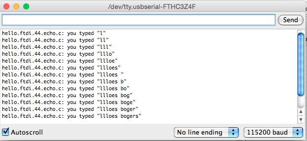
HA! Ok back to C. I went through the tutorial. I SKIPPED THE BOOTLOADING STEP, and tried uploading Neils code again. And win! I had to unplug and replug once and then it worked with serial connection in 115200 Baud rate
When that worked I had a go at rewriting my Arduino code as C code. I found this Instructable as a starting point (basically the Arduino Blink sketch written in C. I asked Dennis, one of my students to explain a little of the C code so I could annotate and change it. He wasn't very familiar with programming hardware in C but could recognize some of the syntax which helped me on my was.
With the instructable I was able to recreate the LED as output but got confused about all the DDRB, PORTB and PINBs in the code. I had to read this article to understand how registers work and how to set pins as inputs and outputs. To summarize: if you know on what pin your LED or SWITCH is sitting by reading the schematic and then reading the diagram showing the pinnames as recognized by the attiny (same names you use in C code), then you also know what register you are working in.
Eg. in my case: in the schematic, my LED is on pin 6, which equals pin PA7 on the microcontroller (the number on the left next to it). My button was pin 10 = PA3 on the controller (and referred to as PA3 in the C code). So both my input and my output are in the A register. SO: anytime I see DDRx, PORTx or PINx (x being A, B, C or D), I should change it to DDRA, PORTA, PINA
The article above also helped with deciphering existing code and info found in the datasheet. I read the datasheet before going into the C code and a lot of things started adding up. Then the main loop looks alright and I wanted to test it.
Executing makefile, uploading to board
change the name to title of my program without the .c extension (the second line in the makefile adds the extension).
The rest can stay thesame
To create make file: change directory in terminal to where your code is and run this command
sudo make -f buttonblink.44.c.make program-usbtiny
Thisis a useful tutorial on makefiles, when programming in C, using makefiles etc. Written for the fab examples. this tutorials list from Providence is great overall.
First try: it compiled but no blinking.....Then to debug I commented out the if loop with the switch and tried to turn only the LED on: SUCCESS!! My colleague Tamara who's an experienced coder helped me with debugging, she made it simpler really quickly by suggesting to leave out the whole button thing and just start with the LED, if that works, take next step. Gooooood tip, thanks
Then I had to google a little about reading input values from sensors in C. Because I'm working in the A register (getting analog reads), I had to enable the internal pullup resistors that turns a floating value into either a HIGH or LOW value. This article explains really well how to do that in C. It also explains quite well how to configure a pin as input and how to get a reading from an input pin. I had to test some stuff a few times and change some things to find out, but finally: success! Then I cleaned my code because I did some unneccessary extra things in it.
In conclusion: C is definitely a lot harder but you can figure stuff out with good examples by others to work from. The HUGE benefit is that you can upload so much more code to your board than when using the arduino IDE. It's much much more space efficient because it compiles it into computer language before uploading (so efficient, I like) Also the way it's written, it actually makes more sense when you look at the hardware, it refers to stuff as it is no beating around the bush with non-sensical representations. Which is all nice. And a bit harder. By the way I must confess that I totally tried to avoid any hexadecimal numbers because my brain can't take that yet.
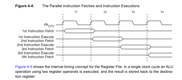
Contains overview of the pins and their functionality, and also describes the toolbox you'll use it with. Eg. it's based on the AVR architecture, and that it is reprogrammable in-system with AVR and C. It uses Harvard architecture and it explains that it briefly overlaps: while executing something, it's starting up the next command.
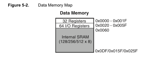
What I already noticed when working in Arduino: there's room for 4Kb in the Flash Program Memory, separate from that is the data memory. The attiny44 32 bytes in the register file, 64 in Input/Output memory and 256 bytes RAM.
It explains a bit about why you need a resonator/clock and which kinds do what, somehow. This is a bit vague to me but I understand that the kind of resonator you choose influences the accuracy of any timing you program the microcontroller to do. I read this article on stackoverflow which clarified a bit. Also it stated that the default oscillator is 8 MHz. There was some confusion as to whether we should set our attiny to 8 or 20....You can do both, 8 is just default and for 20 you need a crystal resonator, I think (not 100% sure) but we all have one of those on our echo boards so should be fine.
Apparently you can also save power with this one because it can have a standby mode. Eg if you only want it to do something once every hour. Not sure how to make use of that just by reading this though.
I read that it has built-in protection against current drops or socalled brown-outs. And it explains the ways you can reset the controller in §8.2. The C code examples were also good to have a look at but it's very far from human language and would need some diving into for me.
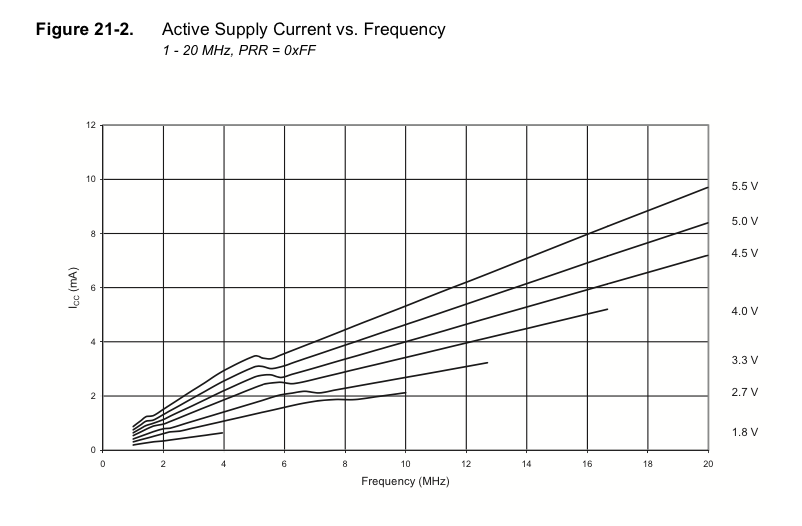
then there was a whole bunch of stuff I didn't really get until I got to noise canceling techniques: could be useful, although I suppose this will be important if your trying to do very advanced stuff with high accuracy. Chapter 18.7 on preventing flash corruption during energy drops could be useful I guess. Annnnnddd chapter 19.2 on fuses kindly reminded me that fuse status is not affected during resets/chip erase. If only it were that easy (see above). !9.5 on serial programming says something about needing en internal clock for serial programming (which we have: the resonator).Maximum operating voltage = useful ofcourse. And this correlation between frequency and active supply current gives an understanding how to choose power source. Followed by a load of other graphs that explain relations between configurations.
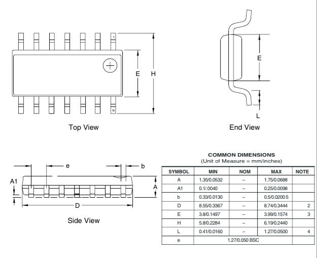
and finally a bunch of packaging info, useful if you need to design your own footprints for eagle board layouts and such.
Wow they're really on top of things at the datasheet offices: even an overview of all revisions made to the information at the very end. Tight ship they run. And an index, always handy especially for these big ones.
Reference: Arduino commands that should be supported: