Assignment: Design a board with a sensor, produce it, program it to sense something
Plans: Microphone & Conductive stretchy fabric
My plan for the week was to use two things that have my interest. One is a microphone because I'll probably use it in my final project (the big moving bird kit as the plan is now). I want to use sound as a trigger to start the movement.
Secondly, I wanted to try something that I had lying around, not necessarily for the final project but because it's an interesting material and I wanted to try something that wasn't covered in the examples yet.
Ideally I'll catch the two in one board, for a challenge, but basically there's no need for that because the boards will probably be more useful separately.
Design choices and restrictions
The stretchy textile board
Connecting the textile piece? I was thinking to clip a crocodile in two, and solder the wire onto pads. The crocodiles can hold the textile in place. (OR: you can change it for something else conductive! ANYTHING CONDUCTIVE to make a switch :D
In order to do so, I put a a throughhole LED footprint in the schematic on pin PA2 to make soldering holes and pads for the clipped crocodiles.
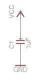
Calculating value of additional resistor on the sensor pin. If I didn't want more than 5mA running on the pin, and the Voltage from the USB will be 5V, I will need a 1K resistor.
Basically I will be measuring the diffence between VCC and ground on that pin. So I need to put the pin between the resistor and GND! (Not the other way around, as I initially thought.
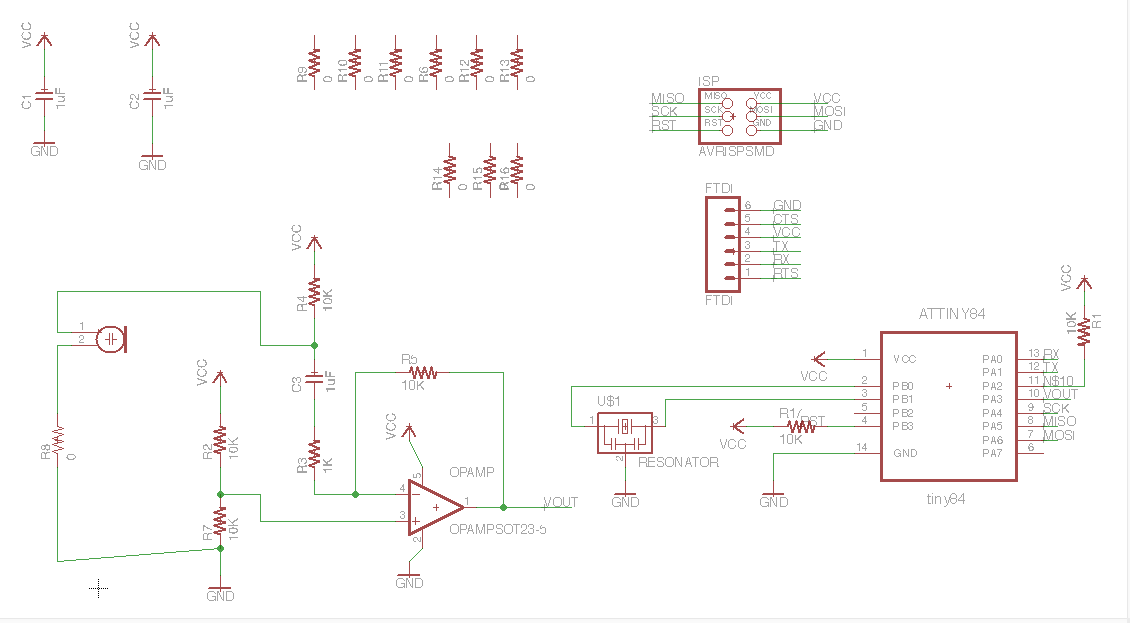
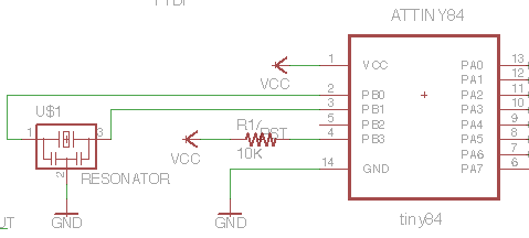
it says ATTINY84 in the schematic, but I'll probably replace it with the ATTINY 44 instead.
I looked up if I had another PWM pin free on the IC and added an LED there, so I could have an LED indicate the changes in resistance with its brightness.
Hahaaaa later I found out I forgot a 10k resistor - VCC combination on the RST pin. Now it will be floating and probably give lots of problems. This needs to be changed before I proceed. I didn't get around to this and moved on with the MIC board.
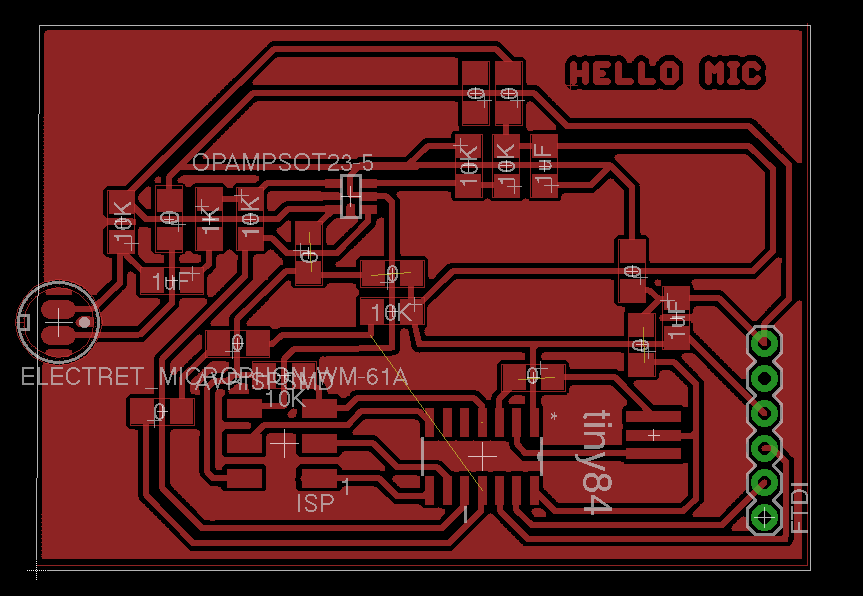
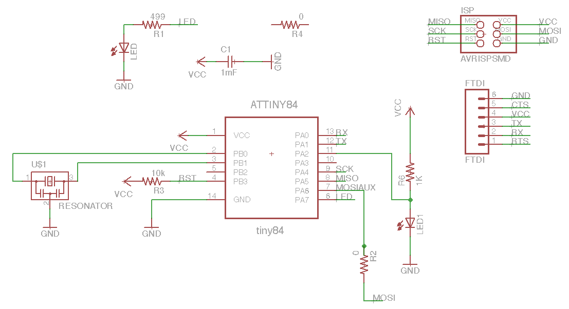
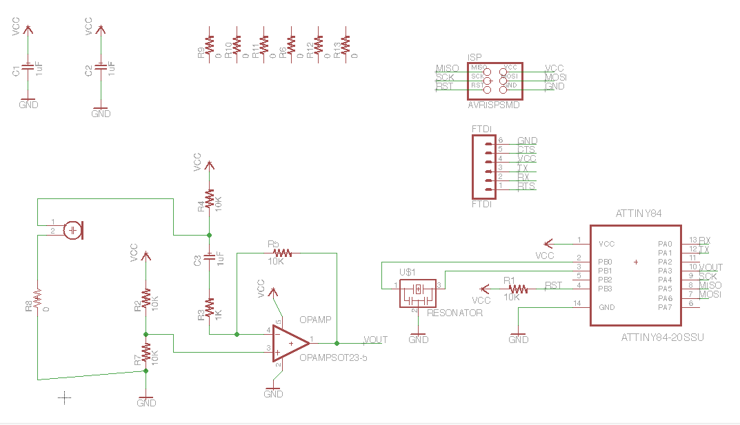
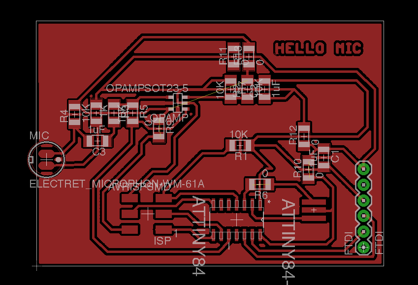
The Mic board
Emma suggested to use an ATTINY84 for an IC. It has the same layout as the 44 so easy to swop and use because I've worked with it. But it has more memory and more pins (that in the end I failed to use unfortunately). But the extra memory will come in handy when processing the audio.
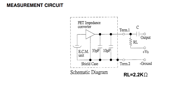
I decided to add a resonator to the boards for more accuracy: 0.5% rather than 10% by adusting the timing of the communication in the software.
I looked at Neils example and saw that he tilted the mic to the side to solder it to the board. I think becausse the legs are too thin for the 1/32 inch milling bit to mill appropriate holes. So I kept the mic on the edge of the board and I chose a surface mount device with pads in the same place to add the footprint.
Fly like an eagle, and crash and burnnnnnnn
Well, I didn't take off like an eagle this week. I really had to dive back into it and ran into some problems that I should be able to fix but probably documented poorly what I did last time. An overview:
There was no footprint for th mic, so I looked up on digi-key the reference number and specs and was able to locate it via Farnell. Farnell offers an Eagle footprint that I could then use. It comes with a ReadMe to tell you how you can install it. Activate the library after adding it!
Make sure the DRU file is correct! The settings should be minimum of 0.4mm for all the traces (1/64 inch milling bit) and 0.8mm for all the drilling holes (1/32 inch milling bit for cutting.
Set the Net Classes too! > Edit > Net Classes > 0.4mm, 0.8mm, 0.4mm
I never thought of this, but I can use any resistor as a bridge! If it needs to cross just cross it underneath.
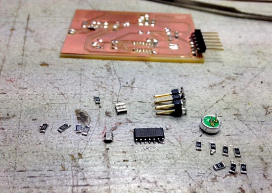
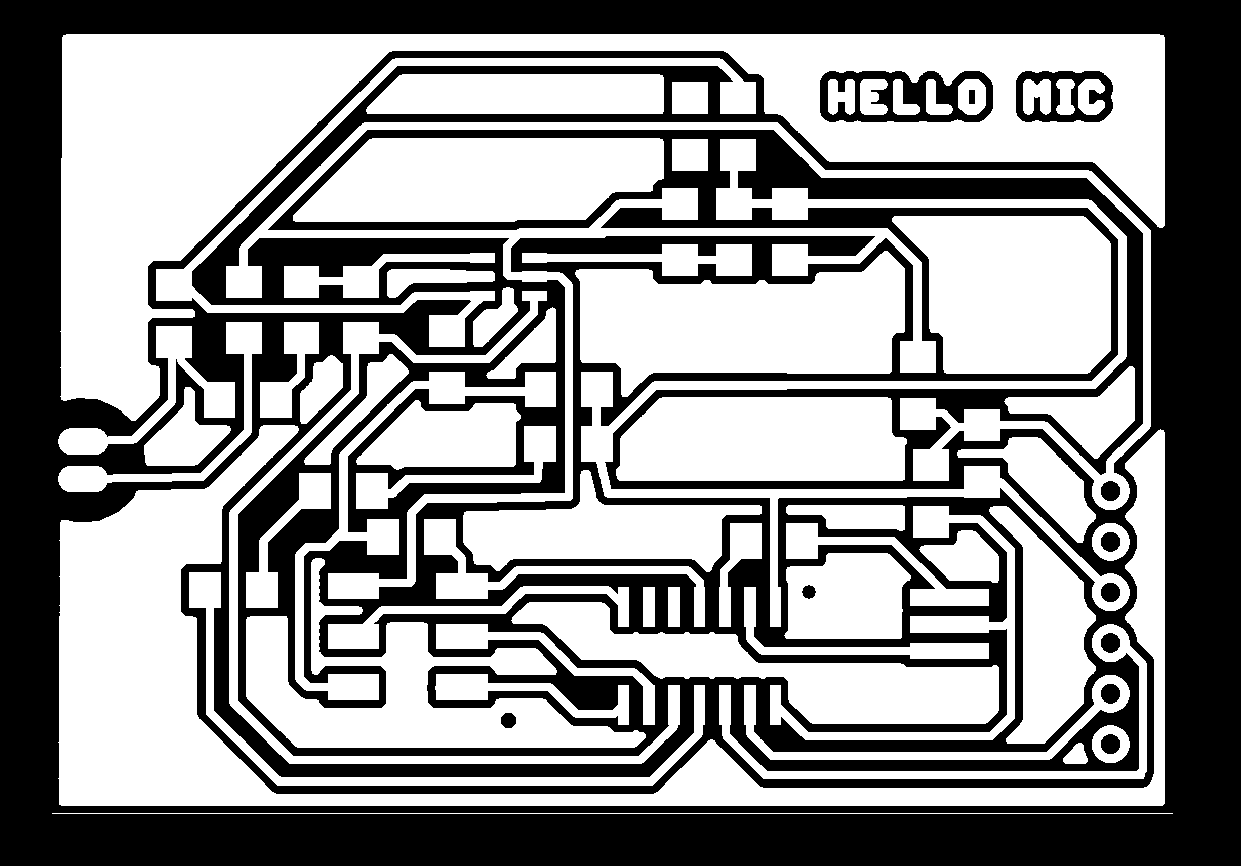
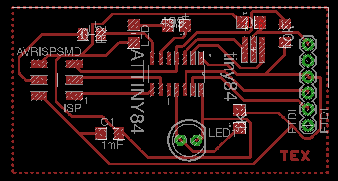
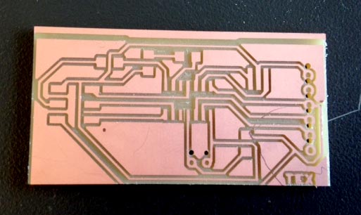
It took a lot of time (2 days) to get the layouts right, so at some point I started to simplify the boards by losing a slide switch, and making a separate textile sensor board and a mic board. The textile board went superfast, no problems. But the mic board was just really difficult to put together and I ended up using a lot of 0 ohm resistor bridges. It's a pity because I don't find it elegant or efficient but I'm working on a deadline here.
when making bridges a grid snap is really handy because you have to be very precise. I set the grid to 0.1mm and then hit CMD when moving something.
I added a dot to mark the MISO orientation (pin 1) of the 6 pin ISP header. I did it in photoshop after I exported the trace file.
For one of the boards I experimented with a different shape. I didn't manage to make a ground plane for that one, probably because I didn't stay within bounds. But I needed to make a specific shape so tried one of Joe's tips from week 6: select the wire tool, activate the DIMENSIONS layer, set wire tool to 0 thickness and draw any shape for your board.
If you know a component has to be on the edge of the board, eg. the FTDI header or the mic, you can lock it in eagle. Handy!
I also tried routing the traces by hand when the autorouter wasn't really helping much anymore. I tried to find some logic in how to do that but I don't really get what is the right hierarchy of setting that up. The article above mentions that it's good practice to put components with lots of pins in an empty space, and that it can be handy to route the power supply first. Hmmmm. Not sure that helped a lot. Also I think it could help to have a ground plane but I didn't figure out yet how that could be useful. But it is pretty so far.
keep tOrigins layer on or you won't be able to move stuff around.
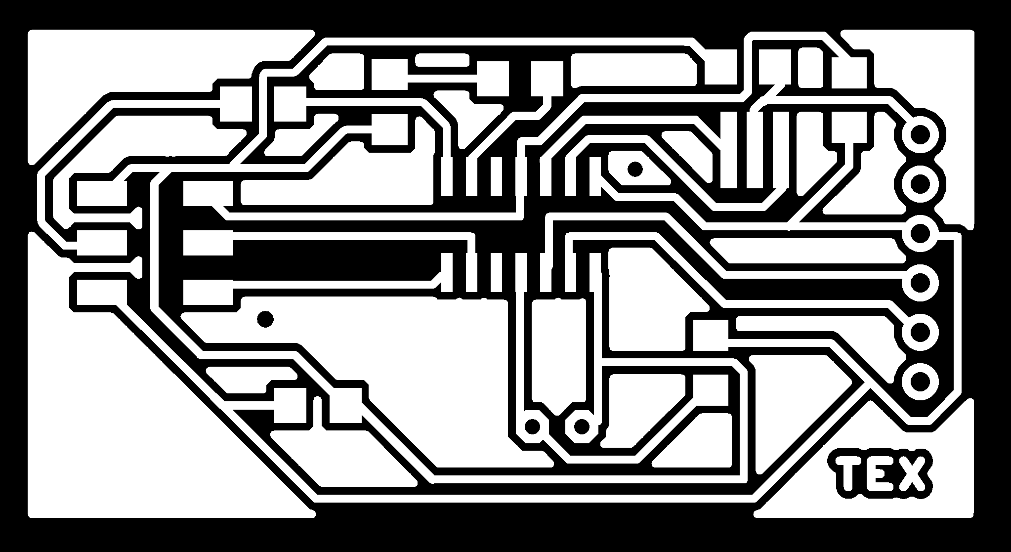
Producing the boards
As I was preparing the fabmodule to mill the MIC board I noticed that there was a really big black buffer around it. I went back into eagle and found out that the value of the ATTINY had a really long name that made the file much bigger than the actual board. Eagle didn't like it, but I changed the value to fix this.
I had to kill the job when I saw that the modela was cutting on one side but not the other end of the board. Probably I didn't do a proper Z calibration and/or the board wasn't completely level. I did the calibration again, and lowered the z to -0.2mm instead of -0.1mm.
Then I had to kill it again because the machine was suffering and sounding funny. I didn't lower the head enough but instead just lowered the milling bit. Because it was sticking out so far it was suffering and I didn't want to break it.
When I got to the cut path of the second board, the machine started losing its orientation. I couldn't get it back to the starting point of the job and it was making weird sounds like it was slipping. We cleaned around and in the machine as much as we could because there was a lot of wax residu everywhere! Like piles of it underneath and inside. We should all seriously cleanup after 3d milling jobs.
We tried a lot of things, online fabmodules, offline modules, turning everything on and off again a few times etc. When we thought it was finally back to normal I ran the cut file. But it wasn't accurate and it messed up my board. So the textile board is still a work in progress unfortunately.
broken tex board.....
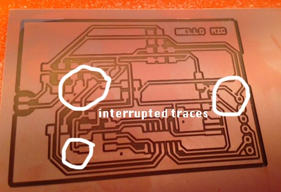
Untraced traces
I had three shorts of traces that didn't cut through! I scratched them off with a stanley knife and checked all the connections with the layout design until it was fixed. Strange though. Also I won't be repeating the GND plane experiment again, the layout becomes much harder to read when going into soldering. I like the plane for aesthetics, but will avoid making it a functional GND plane in the future. By lowering the diameter setting to 0.35mm (instead of the .4mm it actually is) I could trick the machine into routing the traces anyway. I also changed the Design Rules of my Eagle settings to 16mil clearance instead of .4mm because it's more accurate.
Unreadable labels
Some labels in the layout were totally unreadable (take a look at eg the resitors and capacitors in the - old - layout below I made in one of the iterations (it has mistakes!). Resistors from different libs. Some with big labels, some so small they're unreadable/unfindable. Use smash command, click on component, it liberates the names and lables. Right click to open options and change size/move text.
Programming the boards: repurposing Neil's C code
Board
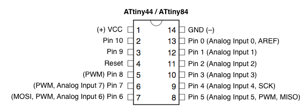
Neil's using a attiny45 , im using attiny 84
Location of positive and negative differential inputs (mic sensor)
Neils pin is on PB4 (see board layout). Mine is on PA3 so different register
In his code I see that he's measuring the difference between PB4 (VOUT from the opamp) and PB3 (10K resistor) and multiplying it with 20 for gain. My schematic, has VOUT on PA3 and the 10k resistor on PB3.
Clock
Mine has a resonator, neils doesnt: he does it in his code. So I can comment out all the delay commands. I left the char delays in there because I think they refer to something else than the clock. I think it just pauses between reading a value and reading the next one.
Serial communication
Neil's serial_pin_out connection RX is on PB2, mine on PA0, so different register, hence:
Neil's serial_port is PORTB, mine is on PORTA (see line above)
Neil's serial_direction is DDRB, mine is DDRA
Location of positive and negative differential inputs (mic sensor)
This can be found in the datasheet in the sections about Analog to Digital Conversion (ADC).
Neils pin is on PB4 (see board layout). Mine is on PA3 so different register
In his code I see that he's measuring the difference between PB4 (VOUT from the opamp) and PB3 (10K resistor) and multiplying it with 20 for gain. My schematic, has VOUT on PA3 and the 10k resistor on PB3. My old student Iain gave the the tip to write the part of the code as an array so it would be easier to find in the datasheet and crosscompare to understand. So simple and yet a huuuge help to wrap my head around it!
This last section is where I realized I was in trouble. Neil's code to specify the pos and neg differential pin is an array of values built up in a sequence: REFS2:0 and MUX3:0. In the data sheet you can look upt that the REFS2: array of 0 1 0 sets the internal 1.1V voltage reference. No problem that can stay the same: I just looked up in the other datasheet how to set the 1.1V voltage reference: it's with REFS1:0 values 1 0.
Then in the MUX3:0 values you set the positive and negative difference input points to measure the difference in the sensor, and you also specify how much gain you want eg. 1x or 20x. Neil has 20. In the ATTINY45 sheet and Neil's code you can see that the values 0 1 1 1 specify 20*(PB4-PB3). But then I went into the ATTINY84 sheet.....and it gives a bunch of combinations, but ONLY pairs of pins on the A register. Crappppp. That means I'd have to change my board layout to put the 10K resistor pin on a PA pin that's free, like PA2 or PA7. In other words. I have to make a new board.
finding equivalents and comparing information from the attiny45 and attiny84 datasheets
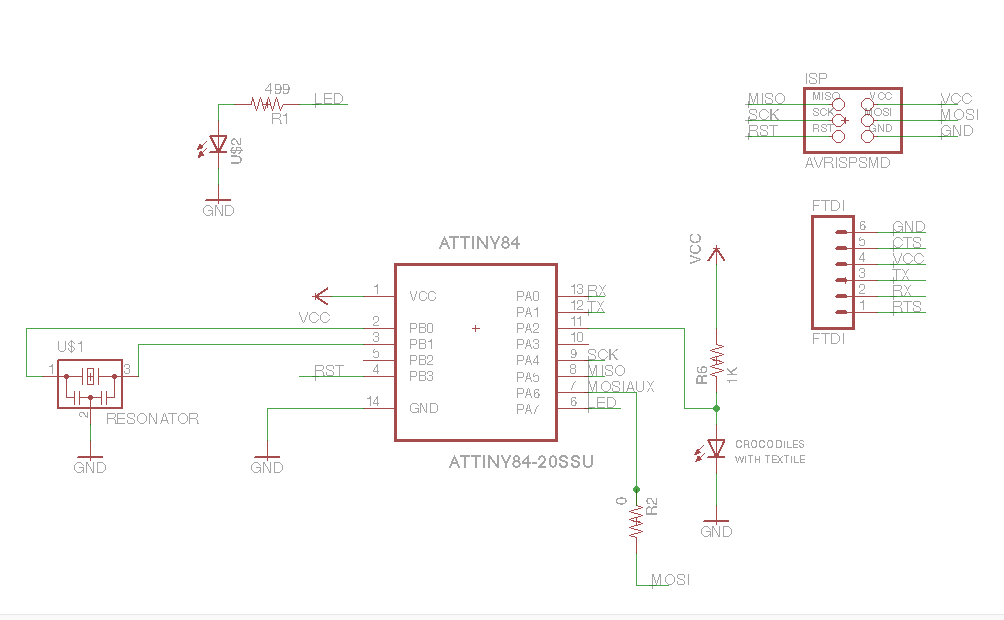
Making a new board!
So! I made a new board with the 10K resistor (the negative differential input on pin PA2 of the ATTINY85) And I had to add another pull-up resistor between the RST pin and VCC. Apparently it needs that.
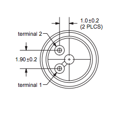
Mic has orientation! See data sheet. Terminal 1 goes to opamp via capacitor and resistor, terminal 2 to GND.
I reused the parts from the first board. Below's the schematic.
Programming the board
change the name to title of my program without the .c extension (the second line in the makefile adds the extension).
Change the value of the clock (in this case I burned bootloader to 20kHz, so 20000000)
The rest can stay thesame
To run the make file: change directory in terminal to where your code is and run this command:
sudo make -f hello.mic.84.c.make program-usbtiny the command I used in week 8 didn't work, it wouldn't upload it, it would just tell me how many bites the files are ahew? I found this command in in this documentation from another student
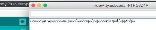
It worked, but then I got weirrrrrrd signals coming through the serial communication at 115200 and all the other baud rates, which, i think should be correct...hmmm. Last time that happened I burned the wrong bootloader. Let's find out if something in the code should be changed or whether I should change the clock....
Wow, one day later. 100 things tried and trialed no luck. We think all should make sense.....To be sure, we checked the board. We used the Oscilloscope to check if the opamp and mic were sensing something. It's weak but it's there...And the code should amplify the weaker signal by 20. About 20 millivolt before the gain in the software. 0.2 Millivolt is the smallest unit you can measure.
Arduino code
Ok so done and over with the C! Wrote this script in like 2 mins and it worked. BAM! Bye.
I found the right names for the pins in this representation image from Hi-Low tech's website that I used in previous weeks:

 Hahaaaa later I found out I forgot a 10k resistor - VCC combination on the RST pin. Now it will be floating and probably give lots of problems. This needs to be changed before I proceed. I didn't get around to this and moved on with the MIC board.
 broken tex board.....
 finding equivalents and comparing information from the attiny45 and attiny84 datasheets