25/2/2015 // Electronics Production //
Making
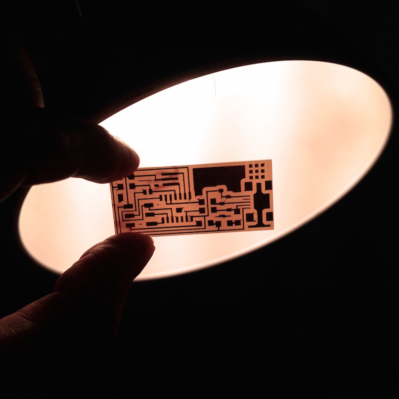
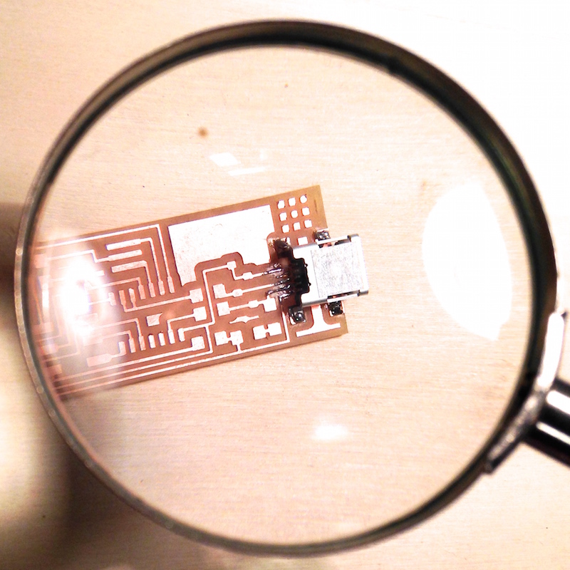
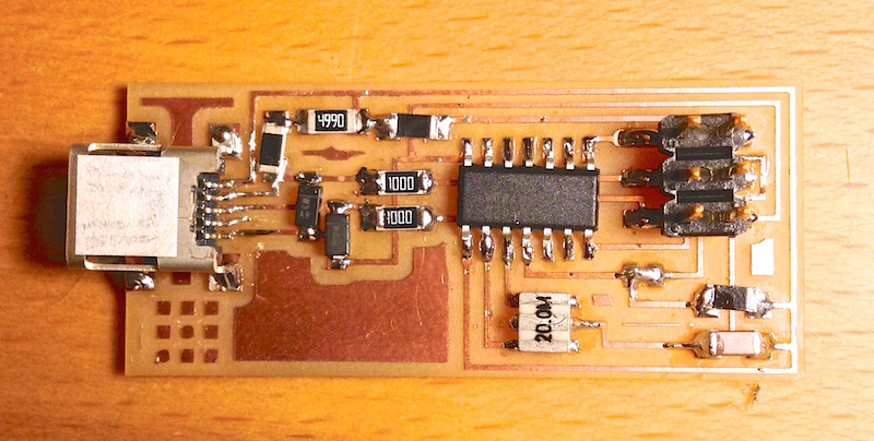
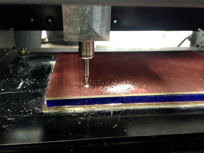
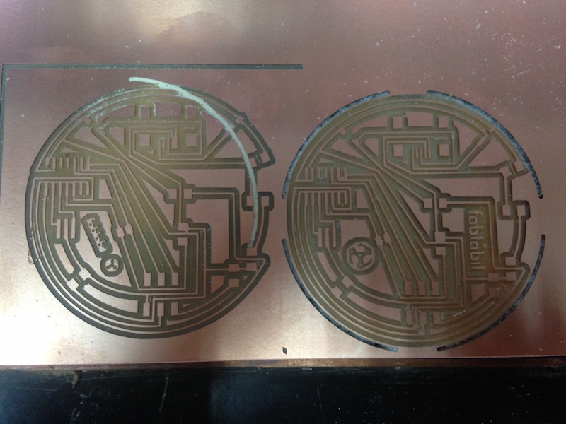
This is my first time for me making this kind of work. We started with milling the PCB as described in fab lab 2014 tutorials. The file was pre made so we didn't need to make one of our own and used that. Once the milling was done I went on to clean and inspect the new piece. To check that all the paths were correct and clear it's best to check them under a light, holding the piece in front of a direct light source. After that the next step was the soldering. The hardest part for me was dealing with very small parts and not knowing how each component looked like so just the process of looking for the components was very frustrating.
Programming
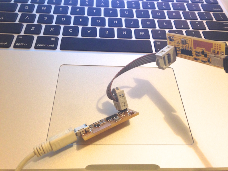
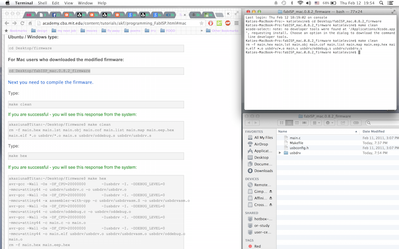
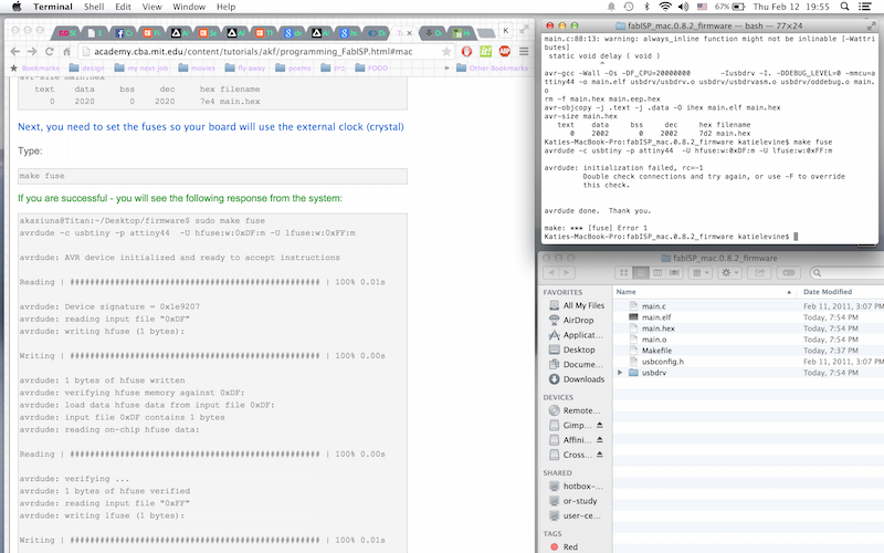
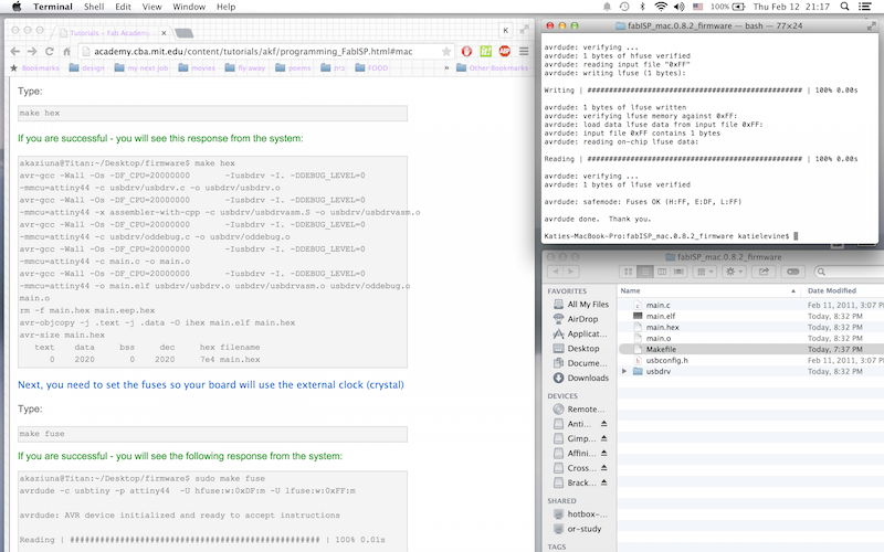
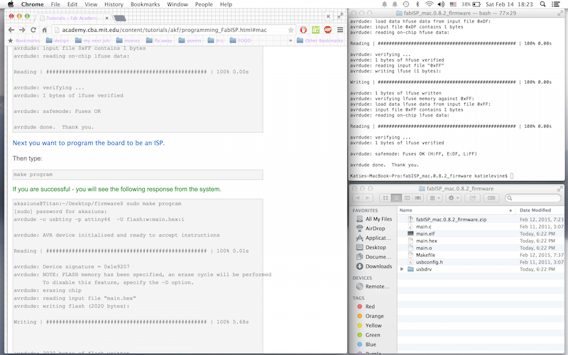
Once the board was done I had connected it to a ready board and started the programming process. At first there were errors so I disconnected it and fixed a few problems with the connections. I reconnected the board and tried again. There was a repeating problem with the fuze. After closely looking at the board again I discovered that I had mounted t-44 processor wrong. Since this was outside of the lab I had decided to try and disconnect and reconnect it at home. It didn't look so good and some of the copper teared and chipped. I managed to connect it properly and even got to program it through only to find out it didn't really work. As it turns out, the chip was fried the first time I connected it to my computer and wasn't viable any longer. Salvaging as many parts as I could I made a new board. [that works well]
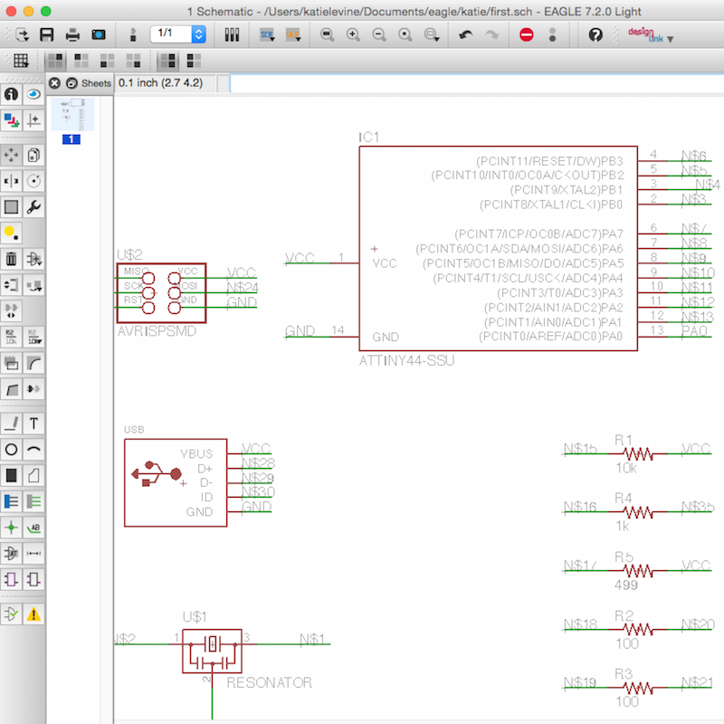
Eagle
To start this segment I turned to the 2014 tutorials of eagle. After I downloaded all that was necessary I began with inserting the components we used on the fab isp board. A lot of them were found in the fablab library.
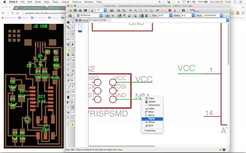
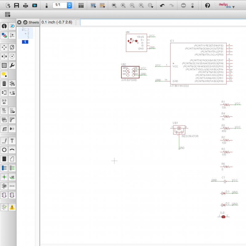
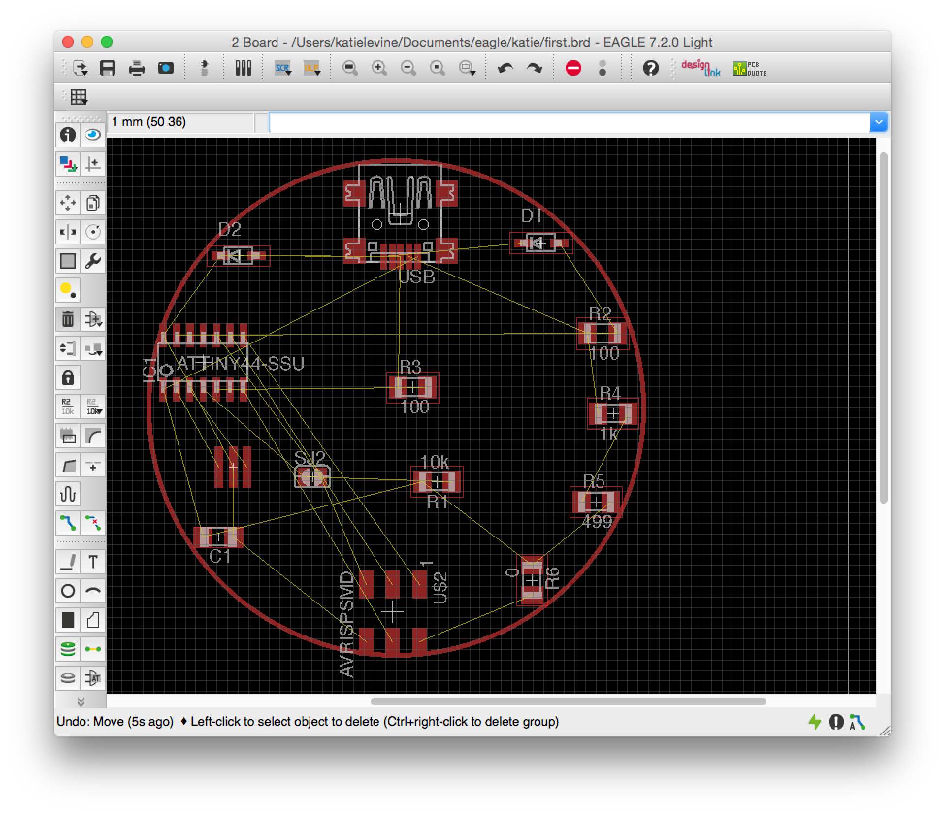
Once I had some parts i connected them. first I connected all the VCCs, then the GND. Then I opened the sketch page and started arranging the connected parts as i went along. After that I was going back and forth to make sure the connections don't get too tangled.
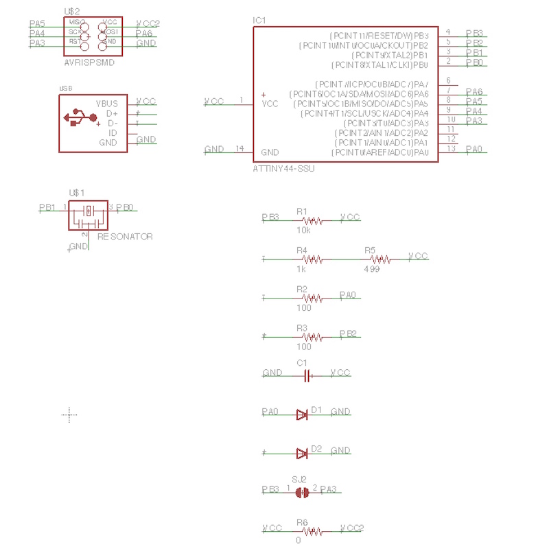
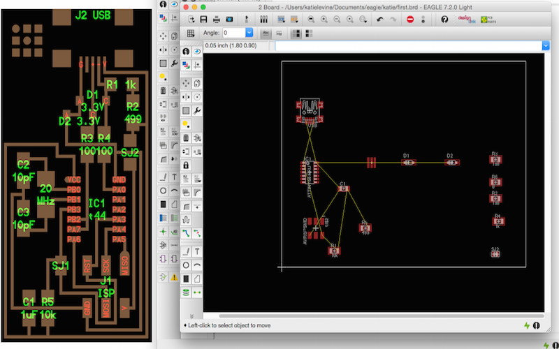
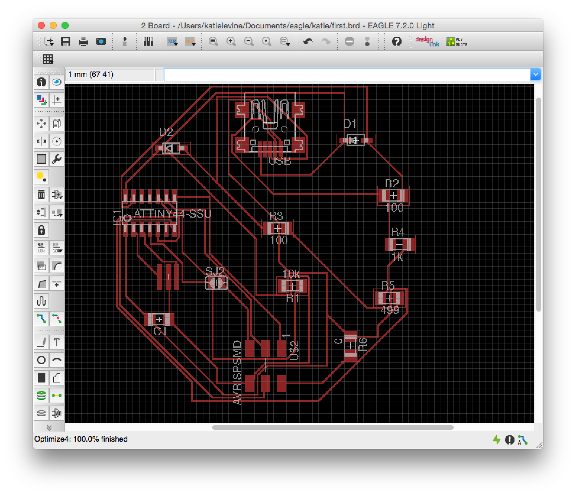
After I had all the components in order I started making the wire connections automatically. They didn't work so well at first so I moved all the components to their place using the fab schematics as a guide. After they were close enough I tried again and succeeded.
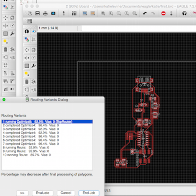
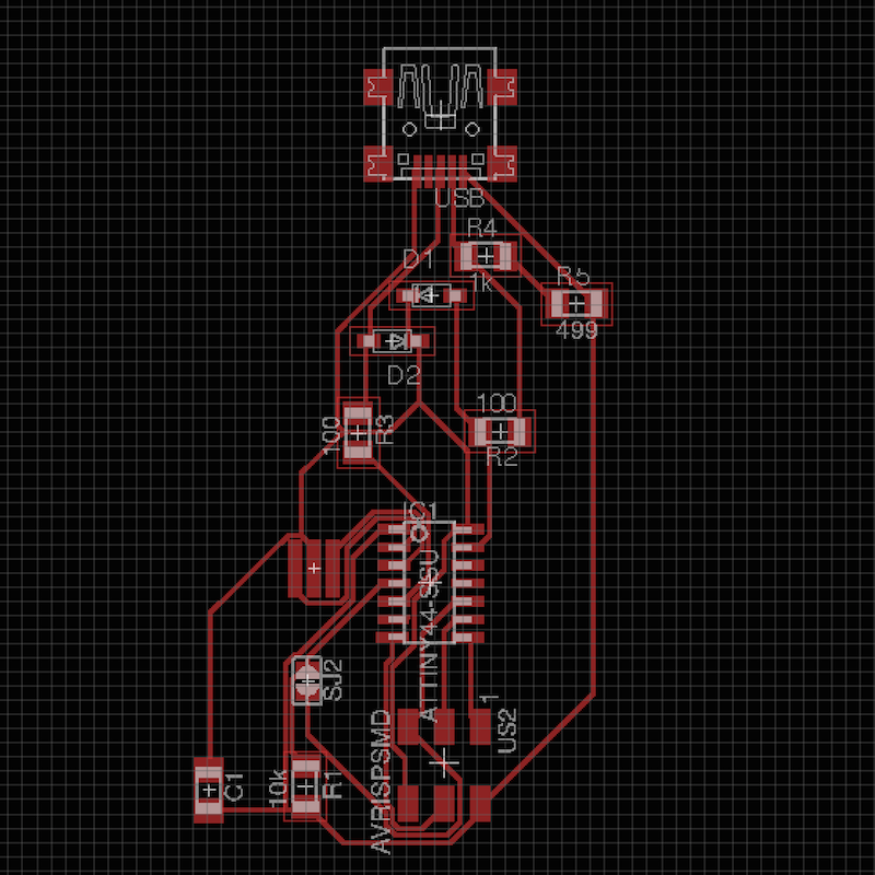
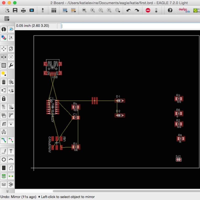
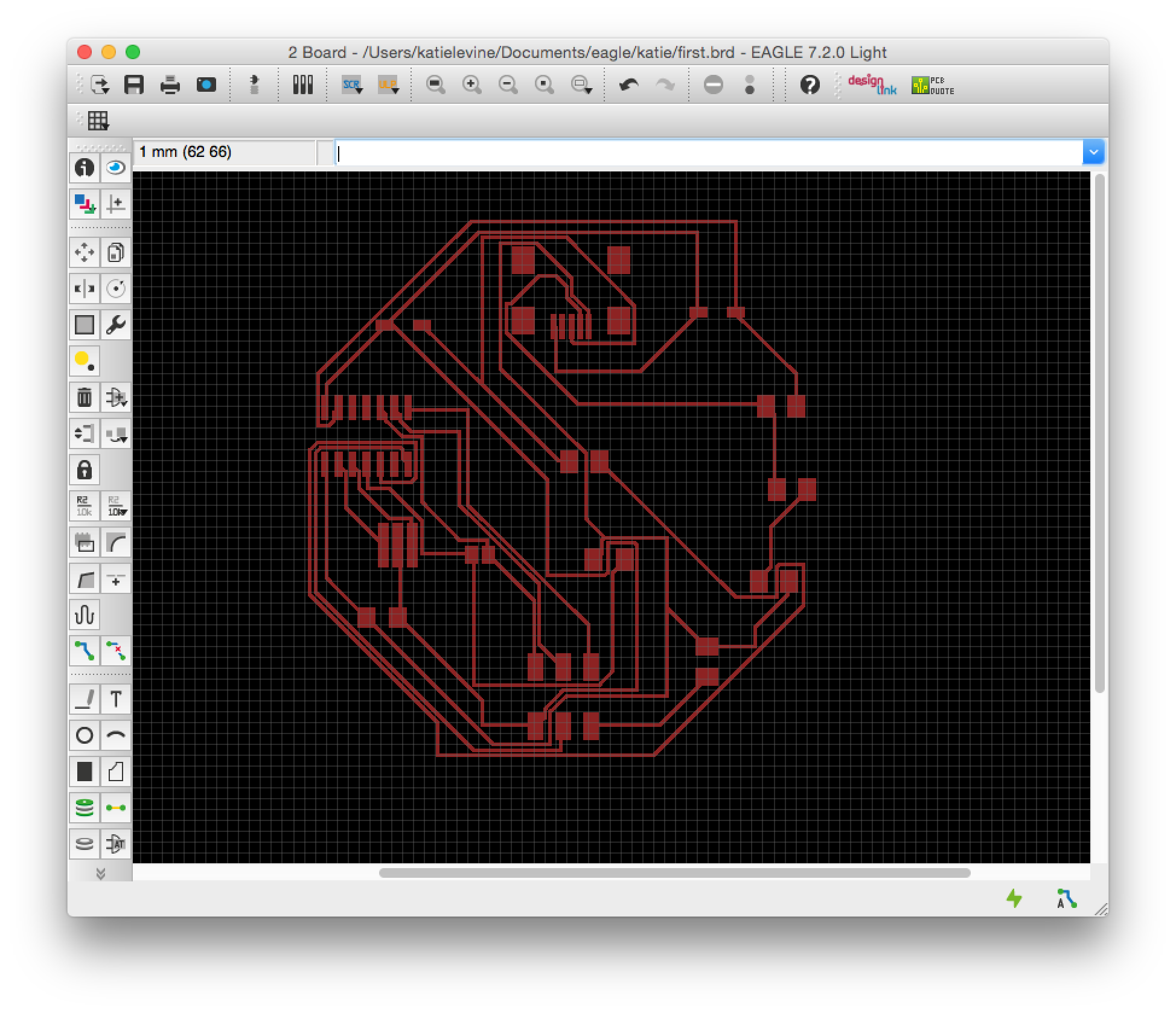
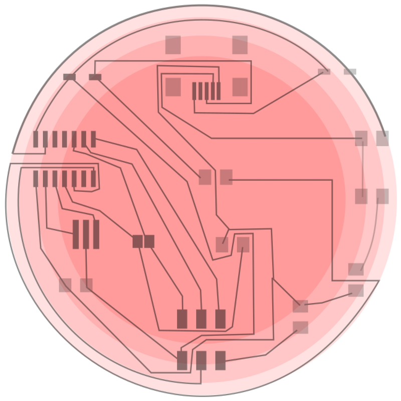
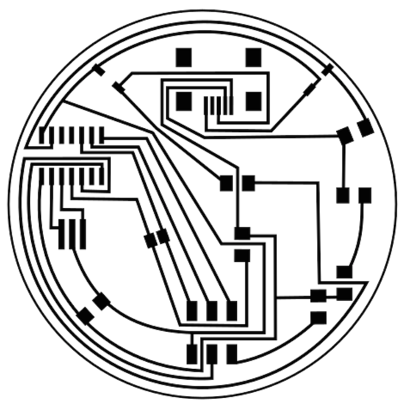
From the beginning I decided I wanted to make a round PCB. Once I had the wiring right I started moving the components around until I got the correct shape. Then I auto wired it again and it was successful.
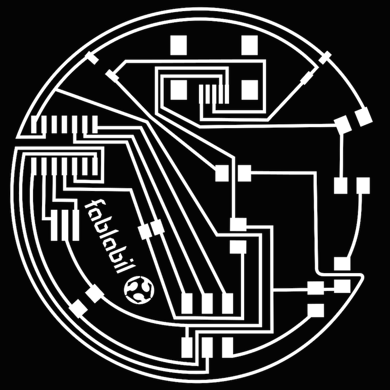
Designing
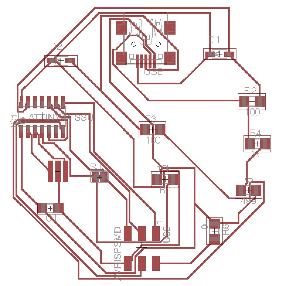
When I was done with Eagle I took the result to Inkscape to do the boards design.
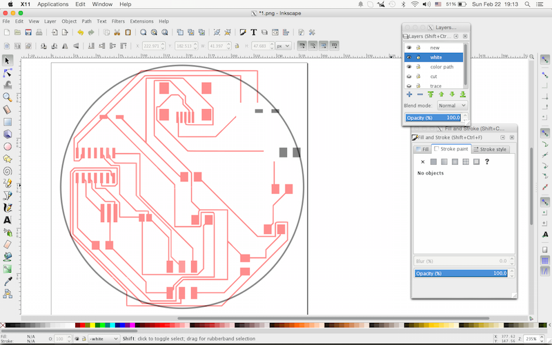
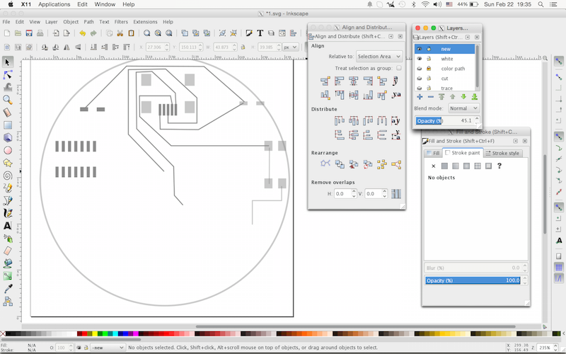

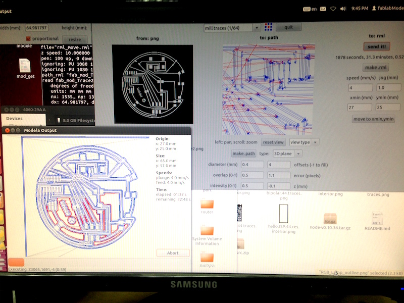
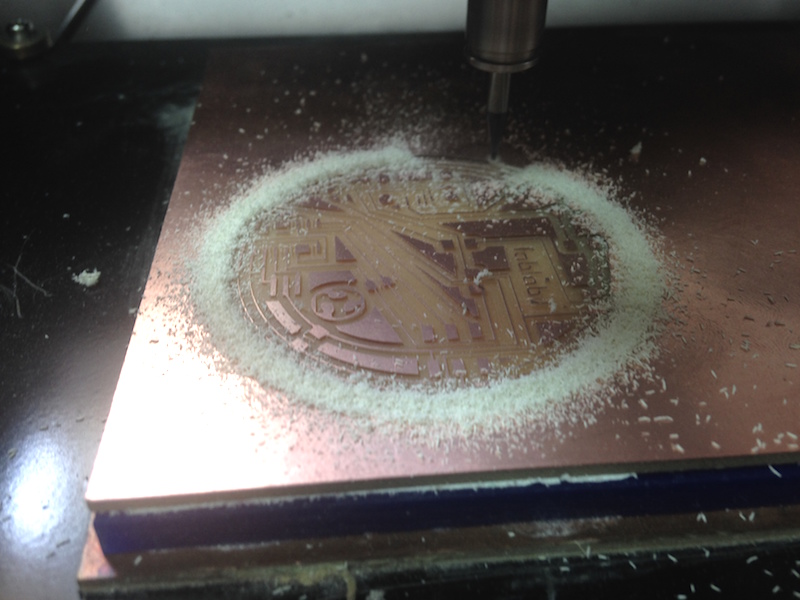
After I thought I was done designing I uploaded the file to the milling machine and started to manufacture my first ever designed PCB. It was going great up to the point when I changed the drill to 1/32" for the cutting process. That's when my second file committed hara-kiri by diverting from the first files origins, completely ruining my design (and again I go..)
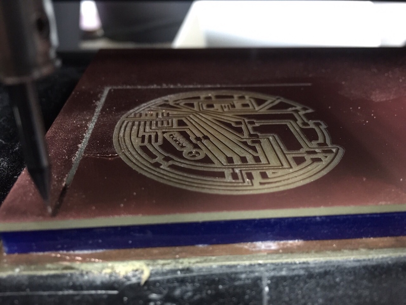
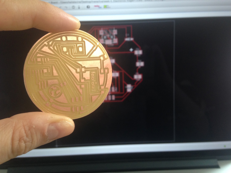
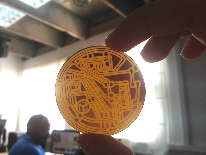
Finally I did it right.. It took me a few tries but it was done. It looks like this:
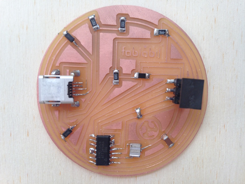
If you'de like to try this out Here are the files I used along with the BOM for the board.