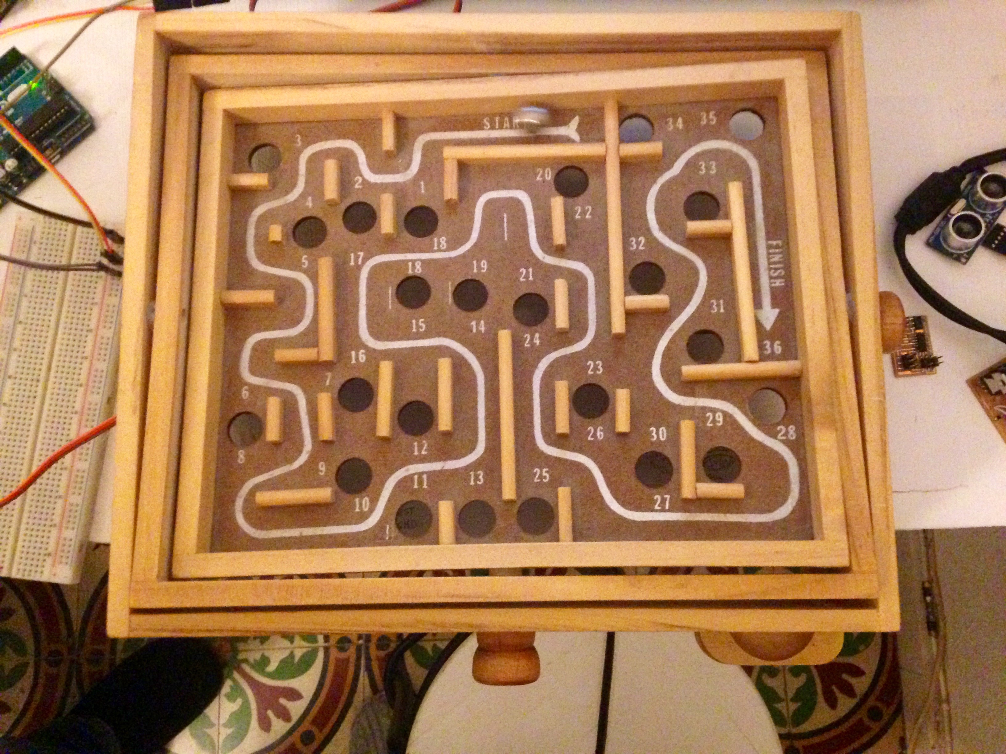
About a year ago I went to Sweden with Or Shoval. One day we walked into a second hand shop where we found an old wood labyrinth. We liked it was a simple game but challenging at the same time, so when came the "something big" week Or decided to scale it up. It came out great and was left in the fablab where many kids come to learn and play. One of them liked the game and had the idea of controlling it with a joystick. It was interesting for us so we decided to make a few games with different controllers. We wanted the game to be fun,challenging, interesting and collaborative. We decided to stick with the original shape of the top board and began working on our individual projects.

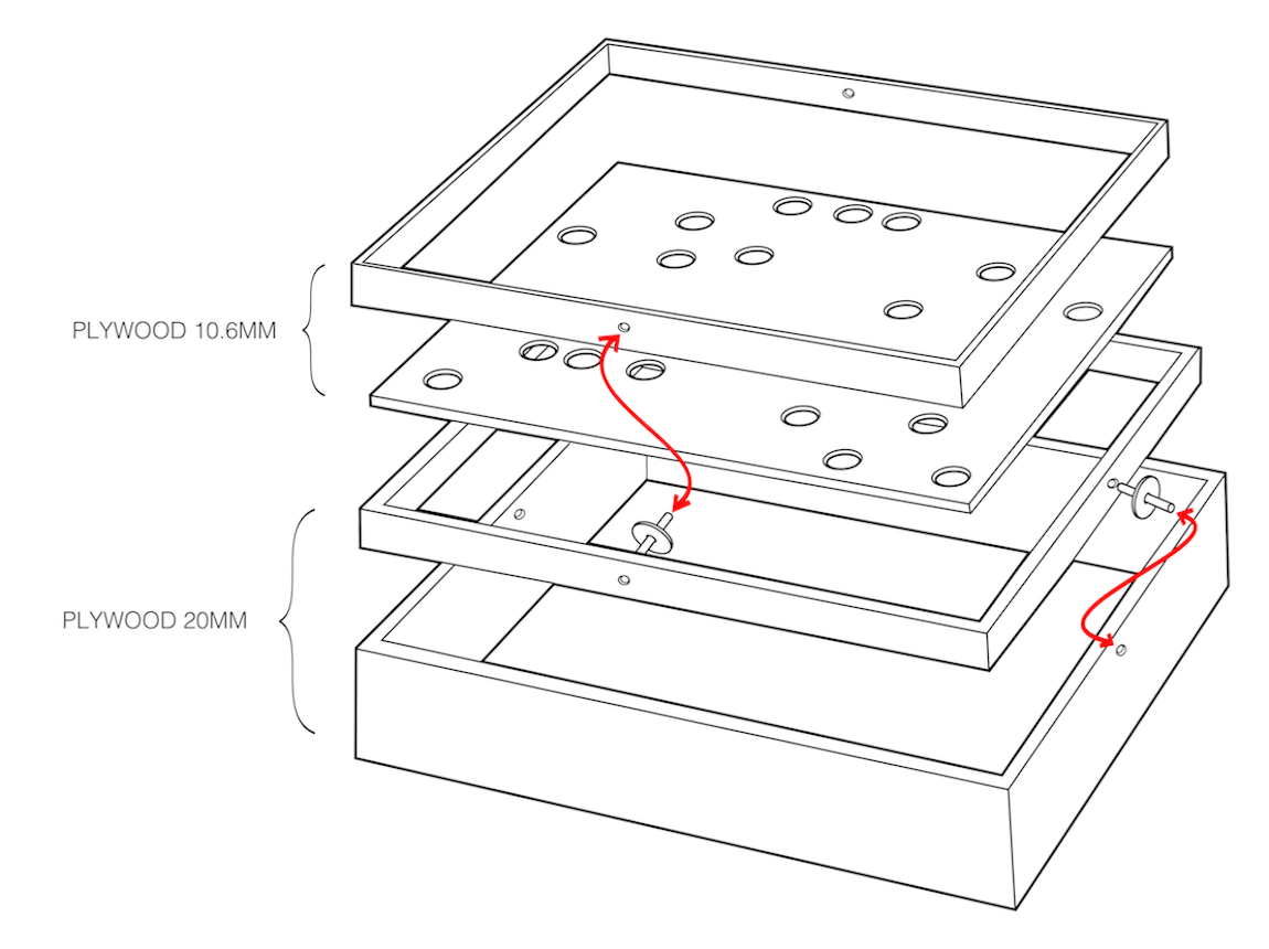
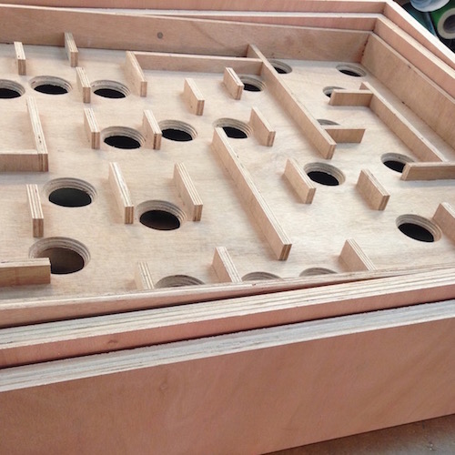
The body of the Maze is made out of two boards of plywood.
For the outer frame and the controllers I used 20mm plywood.
For the inner frames and the top board I used 10mm plywood.
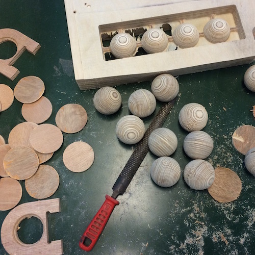
For the balls I used 60mm plywood.
Here's a list of the materials I used for this project and where to find them:
| Plywood 1800/1200/18 mm | $50 |
| Plywood 1000/1200/10 mm | $15 |
| Bendy Flexible Plywood 700/900/8 mm | $20 |
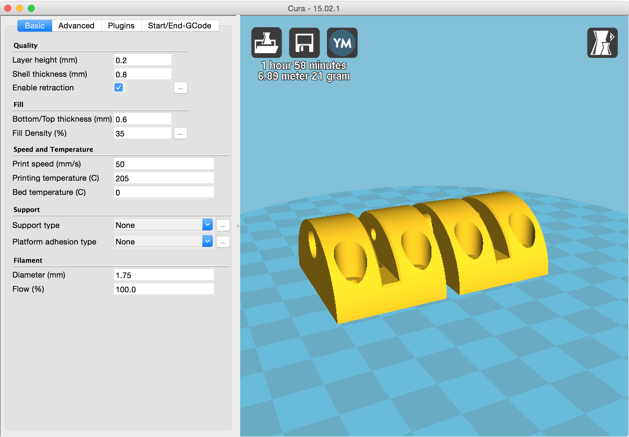
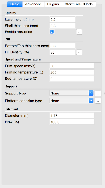
| Pla Filament 21 Gram/689 mm | $2 |
| Ellen Flat Head Screws And Bolts | $1 |
| Blanck PCB 50/50/2 mm | $0.4 |
| ATMEGA328-AU | $3 |
| 20MHZ Resonator | $0.7 |
| Regulator | $2.2 |
| 0k Resistor | $0.1 |
| 499 Resistor | $0.1 |
| 0.1 UF Capacitor | $0.1 |
| 1 UF Capacitor | $0.2 |
| 10 UF Capacitor | $0.3 |
| Tactile Switch | $1.2 |
| 6 Pin Connector *2 | $2 |
| LED Indication | $7 |
| Servo Motor *2 | $36 |
| MPU-6050 3 Axis Gyroscope | $3 |
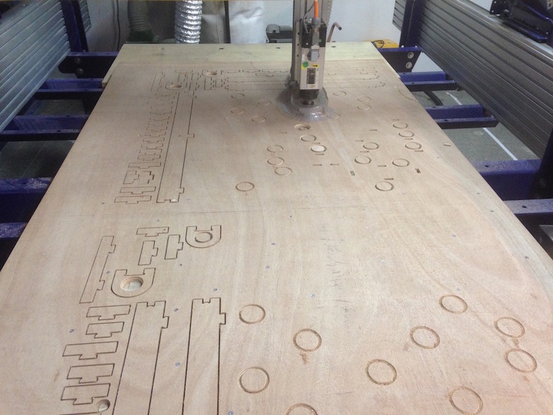
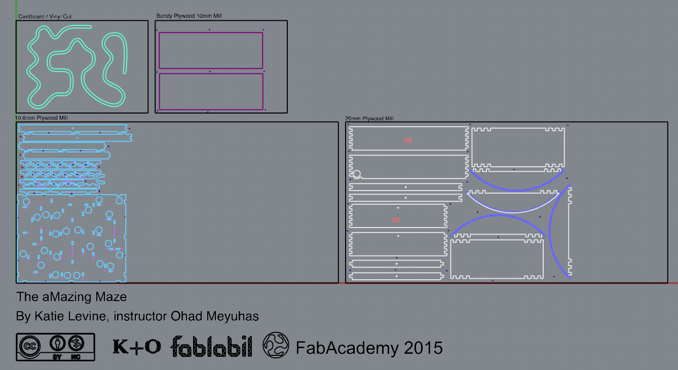
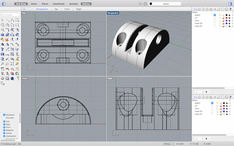
For all the parts I used this file I made with Rhino.
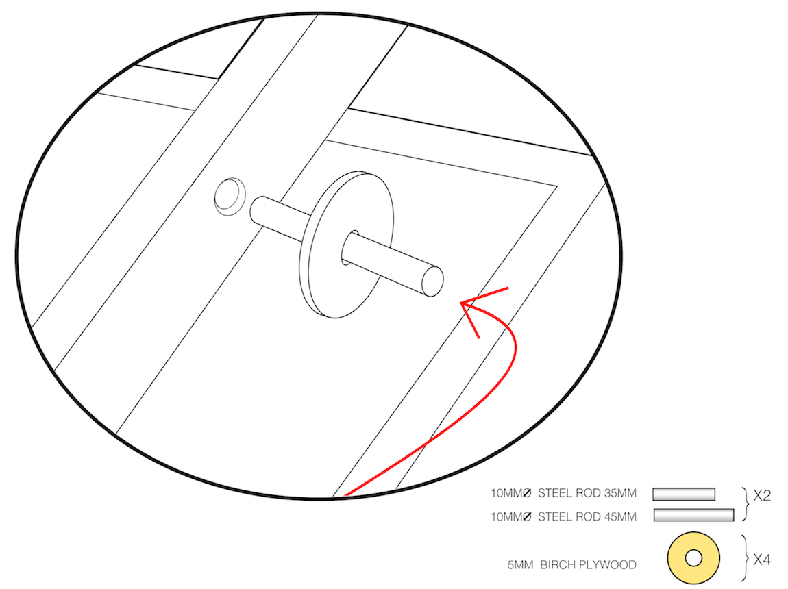
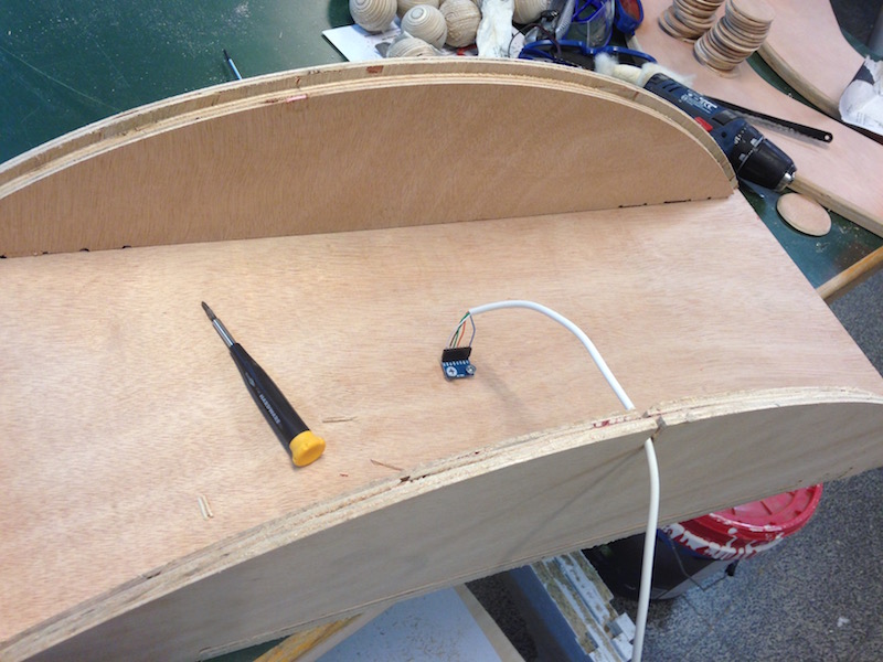
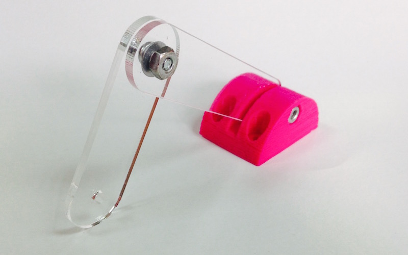
Under the top board of the maze there are two servo motors.
The motors are connected to the top board with a simple mechanism I designed in Rhino.
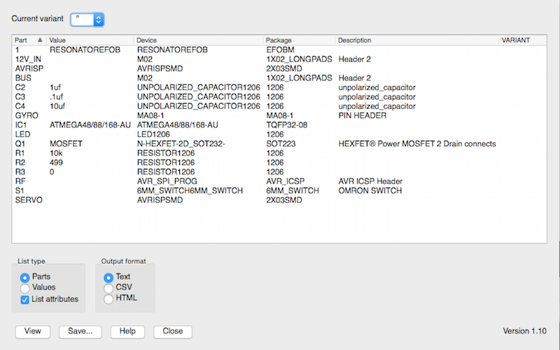
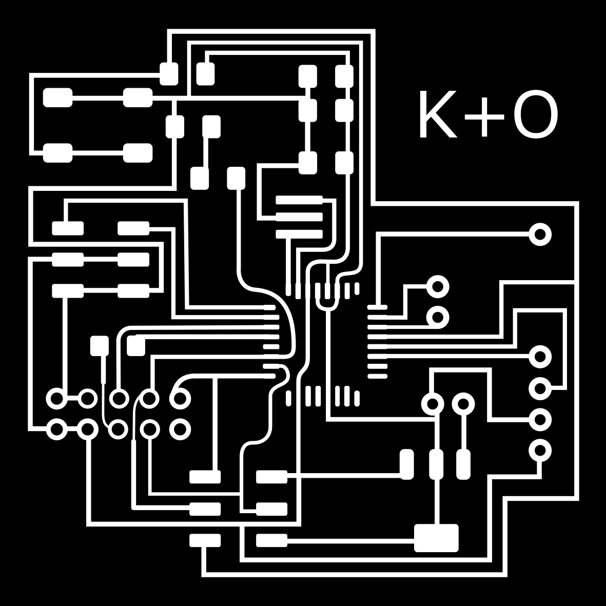
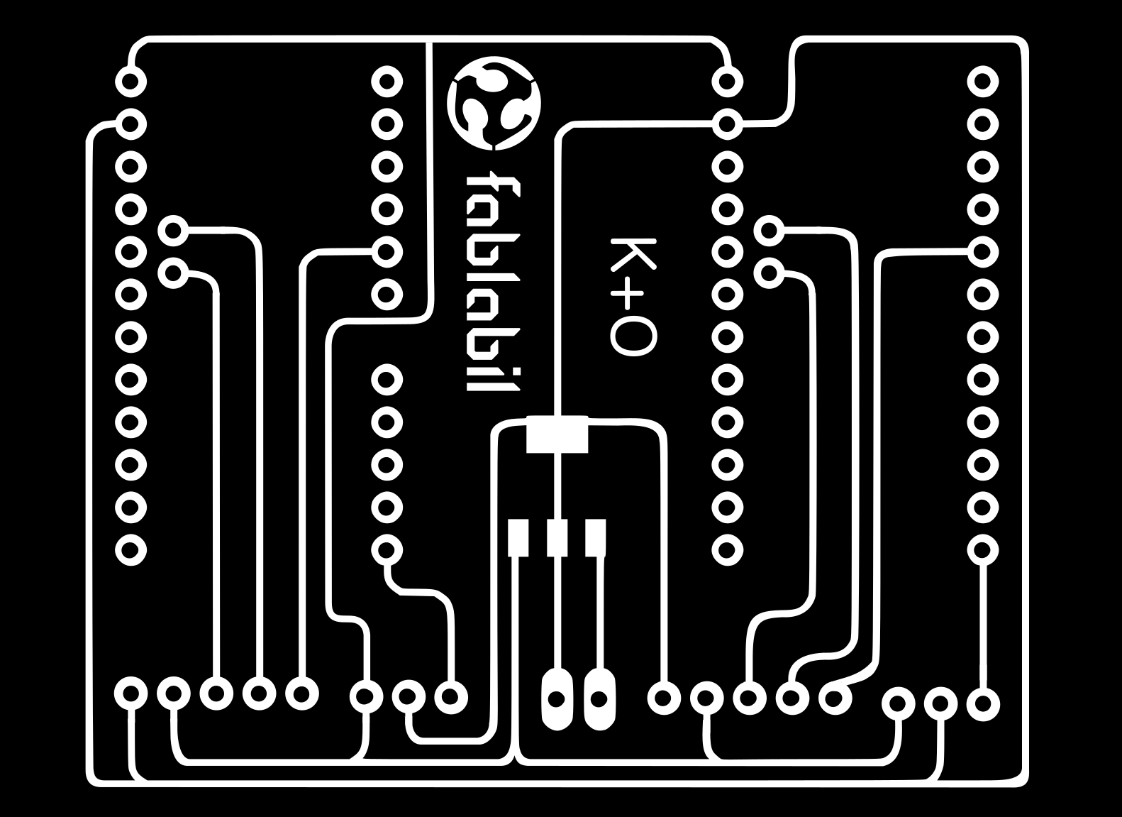
For the electronics I used Eagle and made a specialized Fabduino with servo motor ,Gyro sensor, Rf that can have different functions according to the component soldered.
Here are all the files I made for it.
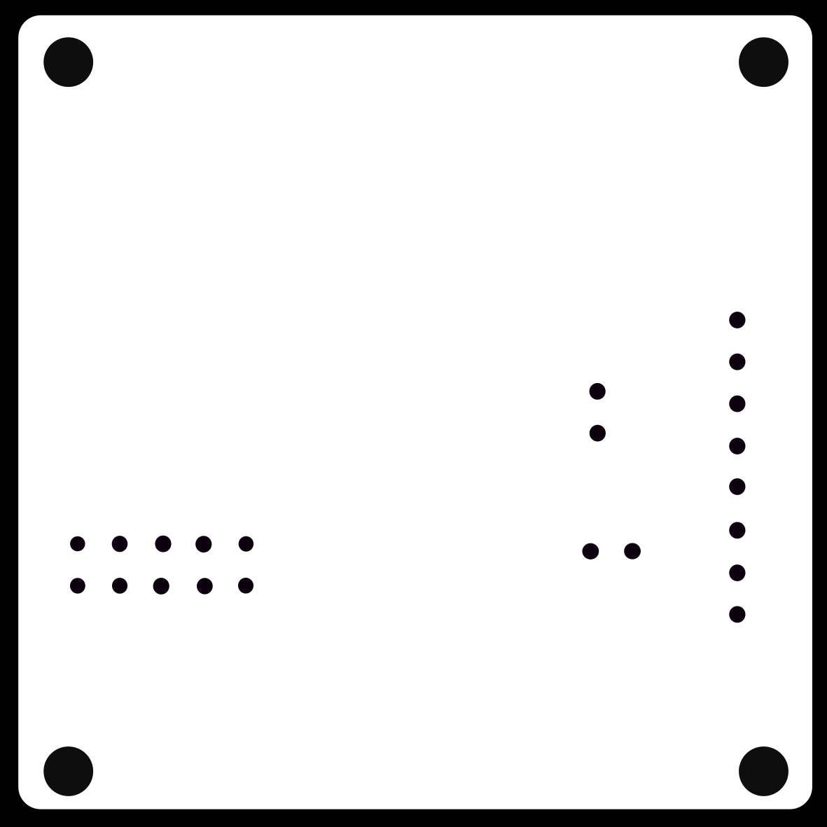
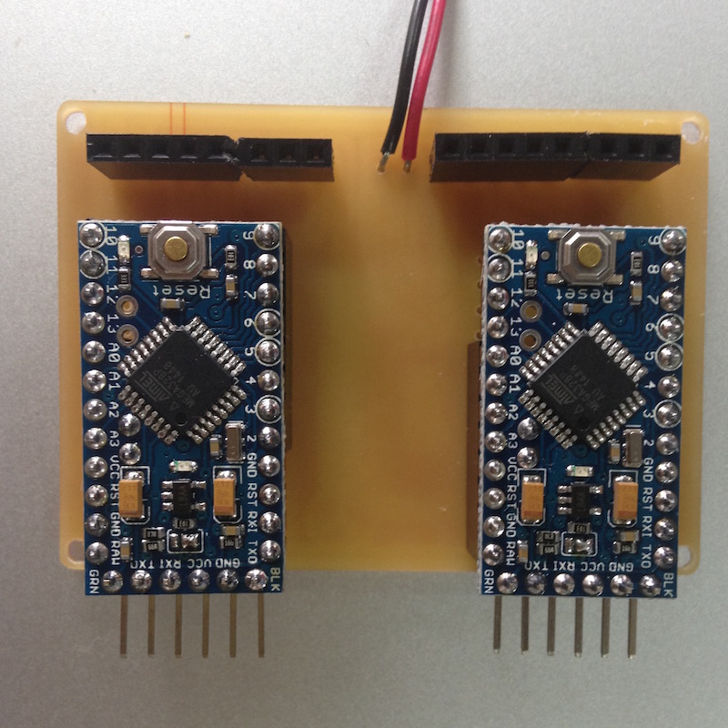
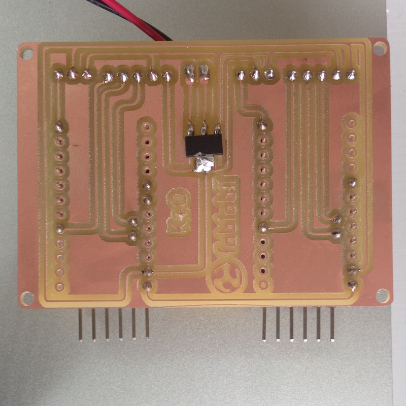
After having problems burning the boot loader [together with the rest of my class] I made a shield for two Arduino pro mini that connect to two servos and two gyros with a mosfet to power them.
Here you have the shield files.

The code for the maze is pretty simple and direct. It reads from the gyro that is connected to the foot control unit and moves the servo accordingly. It analyzes the angle with map function that translates raw gyro readings to angles for the servo.
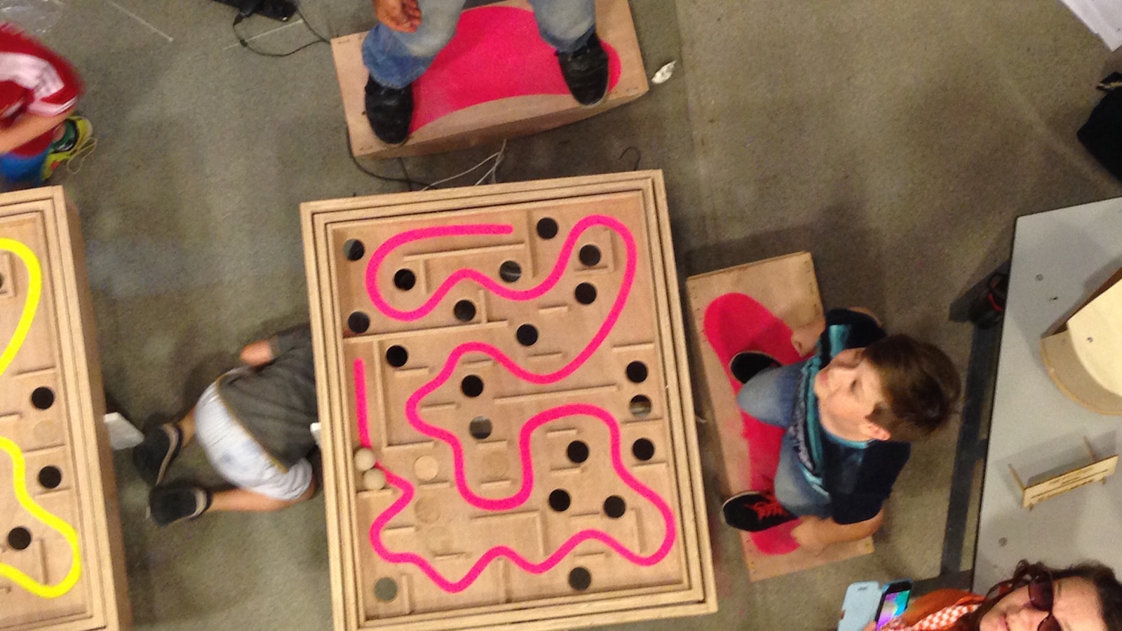
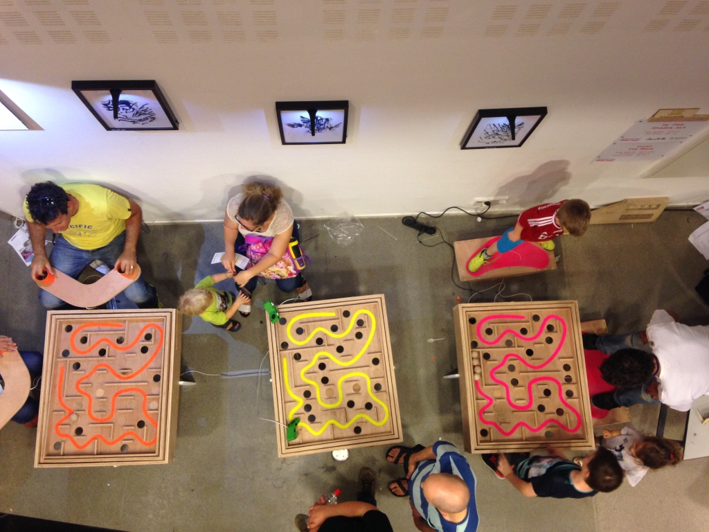
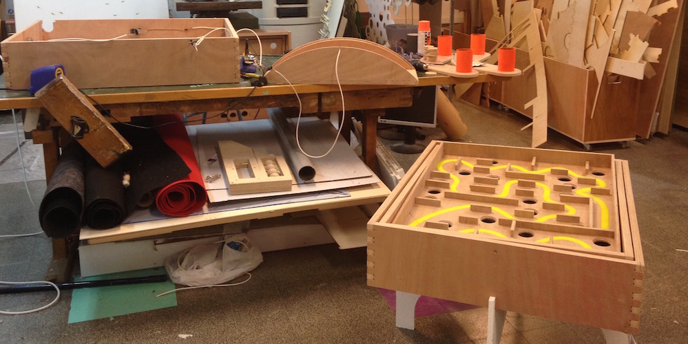
To test our project we decided to manufacture it a little early so we can show it in the Jerusalem Mini Maker Fair.
It was a great experience and we have learned a lot from it.
The best part [other than working projects an time] was the interaction with the little humans and their feedbacks. We also had interest from education professionals like preschool and elementary teachers who thought the project was suited for their schools.
We now aim to perfedt our project and develope it into a product we can make and sell.