Machine Design - Making pretty pictures... WITH ROBOTS!
The challenge:
Design or modify a machine, making as many of the components as possible, document the group project and your individual contribution make the passive parts and operate it manually. Also create a diagram of the physical project layout for their final project.
Plan of attack:
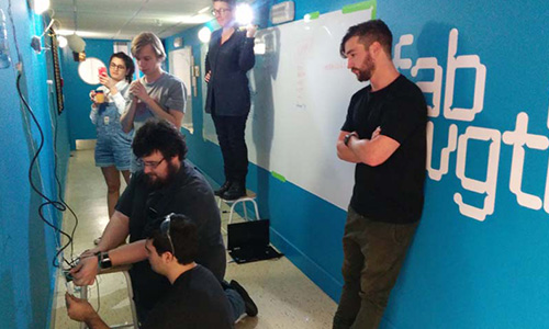
This week we were really under the knife, because of scheduling craziness this was the last week that our whole class would physically be together for an entire week. To take advantage of this we did the machine building a week ahead of the rest of the world. Teaming up to make a fun cnc machine using components we have around the lab.
During this week I also did some mechanical drawings for my final project. Check them out on my final project page.
Game plan and reasoning
To kick off we had to decide on the kind of machine we would make as well as the general approach we would be using for the mechanical design. After a bit of deliberation we settled on building a wall hanging drawing robot. To achieve this we had to make strategic design decisions in three main areas. The motor and drive system, the end affector and the control system. By defining our approach collectively at the beginning we were all able to work independently and know that the final construction would work nicely together.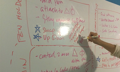
The key choices we made were to use:
-Two drive motors mounted at the top of the work area.
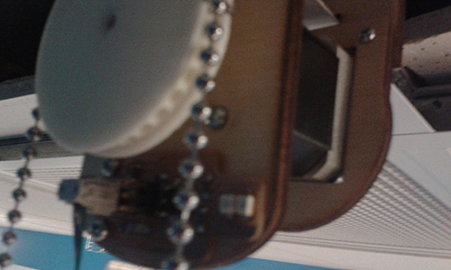
-A counter weighted pulley system over a spooling drive.
-Individual pen lift mounts instead of a total stage lift.
-A weighted gondola as the mount for our pen.
-Adjustable counter weight design.
-Existing open source firmware to drive the controller.
Tasks and solutions
To have a chance of completing this project on time we split up to tackle various challenges in the design. Jasmin and I formed the wall mount sub group which handled the control setup and motor housing. Specifically I worked on the motor mounts, homing switches and firmware calibration.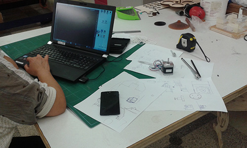
Our first task was the motor mounts. Jasmin and I wanted a solution that would provide us with alot of rigidity and stability but which would be relatively easy to adapt for mounting onto different surfaces. To achieve this we opted for a ply face plate (which also held the limit switch) with interchangeable brackets for wall or roof mounting.
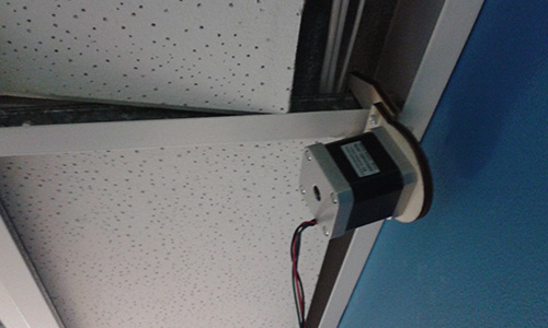
Initially we only had a bracket on the front which caused the motor to tilt and encourage the chain to slip. To combat this we added an additional rear mount hold everything secure and level.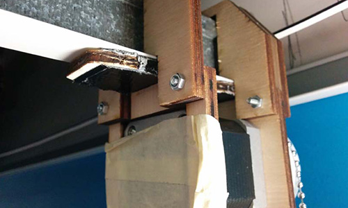
Jasmin and I both worked on a number of iterations for this design to get to all fit snuggly. First working in cardboard and then moving into 4mm ply once the fit was finalised. The final design securely holds the motor parallel to the wall and can be detached from the roof mount to a wall mount if changing drawing surfaces.
One of the goal that was set by the class was for our drawing robot to be able to scale to work on a number of larger canvases around the campus. To help achieve this goal Jasmin and I decided we needed to elected to implement homing switches rather than just using a default center 0,0 system. This would allow us to scale our canvas size significantly without having to be able to access the gondola to reset it. For the switch design I choose to use IR proximity sensors. By attaching a small flag to the ball chain we could detect the bottom of the canvas without having to deal with the physical contact required for normal limit switches. Jasmin and I shamelessly stole Daniels sensor that he started designing in week 11 and milled out and tested his latest version.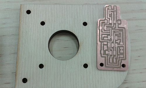
It worked a treat and I simply modified to code to suit our nefarious scribble based purposes. This would be mounted on the counter weight side of the pulley and trigger when the weight was getting too near the top.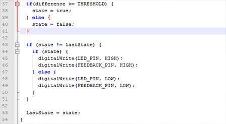
My final task was to set up the control firmware we would use to drive our new creation. After pitching a few possible solutions to the rest of the group, I decided to use the Makelangelo firmware. It natively supports the setup we had designed and would work with the arduino and motor shield we had on hand, perfect! I did run into a few interesting calibration and undocumented fun times in the way the firmware behaves, though alot of these could be pinned on the external gcode generator I was using to create our toolpaths. The most interesting of these was that the Z height must be set to greater than servo lift angle to trigger a pen lift, for ease of use we changed this to a simple greater than 0 equals lift.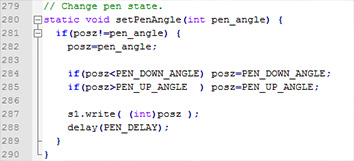
I made some notes about the supported Gcode commands over here. Overall the firmware was a breeze to use and Dan Royer has done an amazing job of developing it and other really interesting proejcts.
There was a firmware update put out a week after this blog post so we will be having a jam with that to see whats changed
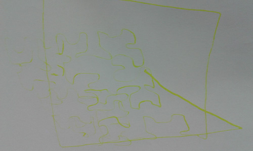
Results
Where to next
There are a few details left to tidy up for our alpha build:
Thickening the counter weight mount to prevent delimitation.Replacing the stepper I accidentally demagnetized (im sorry guys) and changing to pulley so that it doesn’t require grinding the motor shaft. Done, Thanks Wendy.Firmware tweaks to the homing and feed speeds. DoneServo breakout board, for automatic pen lifts and cable management. Done, Thanks Bry
After that some of our stretch goals include:
Developing replacement motor mounts for any additional surfaces we might want to play with.
Three more pens with automatic switching.
Controller autonomy with either SD card or network drawing.
Automatic chalk pen priming.
For more information about this project and to download all the files check out our group project page.
Happy scribbling!