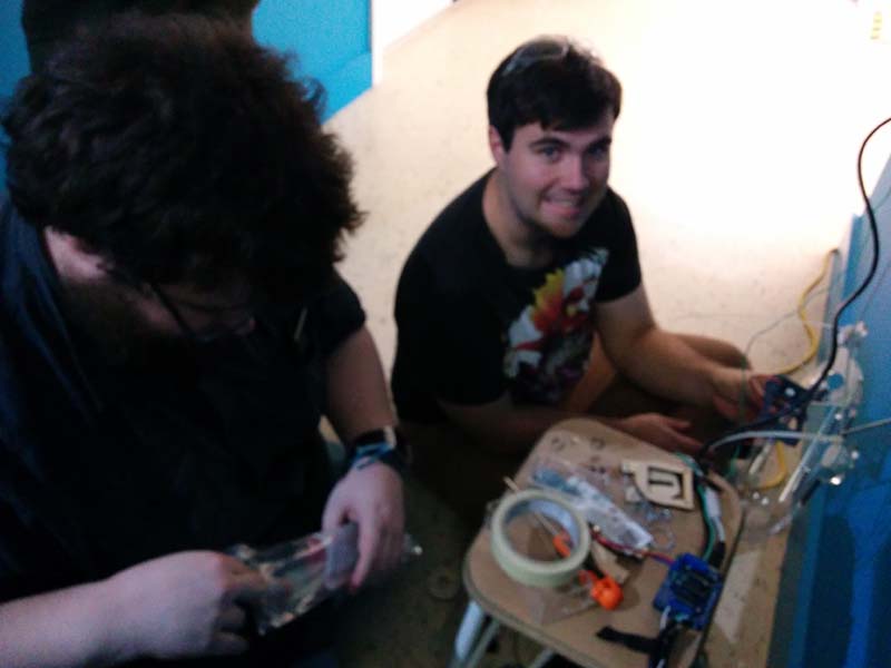
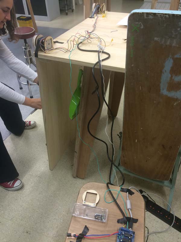
For this week's assignment, we had students coming from out of town to work on the group project, but the parts for the assignment had not yet arrived. We discussed as a group what kind of project we'd like to work on (narrowed it down to a 3D printer or a drawbot), and we voted for the drawbot.
The Scribbly-Bear is a Kiwi drawbot inspired by the AS220 Drawbot Tutorial. We wanted to make a drawbot that was adaptable for many different surfaces - from windows to ceiling rafters to whiteboards to the sides of buildings. The Scribbly-Bear was designed with adaptability in mind.
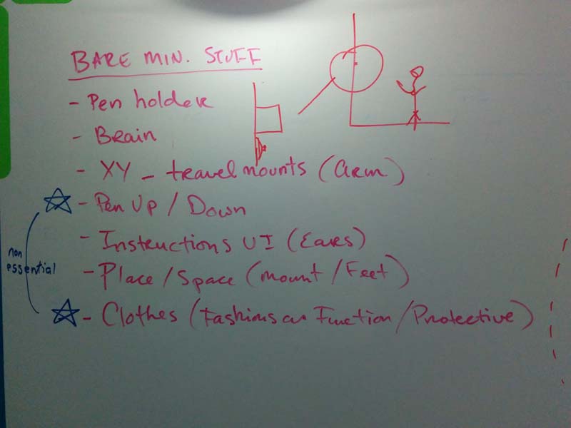
We started with a brainstorm to identify the minimum parts required to make the drawbot work:
pen holder
brain
XY travel mounts (arm)
instructions UI (ears)
place/space (mount/feet)
Some of the non-essential, but nice-to-have features were:
pen up/down
clothes (fashion as function/"pro-tractive"
Gallery
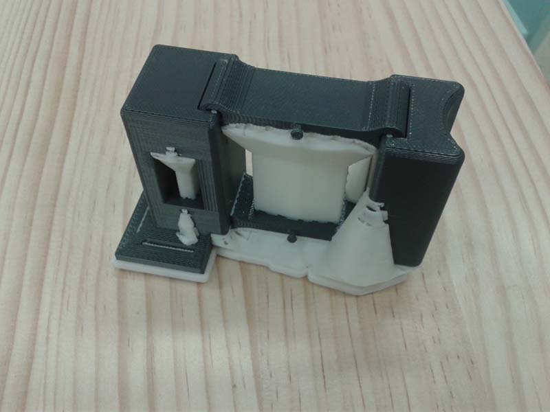
About the Pen Holder
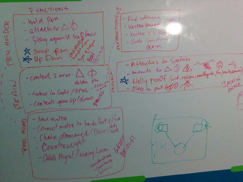
The pen holder had several key functions:
hold the pen
attach to ∆ (delta) and ⦶ (phi)
stay against the surface
Daniel led the design of the pen holder, which was modelled in Solidworks. The holder moves up and down so that it isn't drawing constantly, and can move freely to other parts of the drawing. The piece was printed on the UPrint completely in place.
Gallery
About the Travel Mounts
The travel mounts had several key functions:
hold motors
connect motor to hands/feet
chain clearance/drive (pully,teeth)
counterweight
cable management/wiring loom
To design this, we had to take into consideration consistency and tolerance.
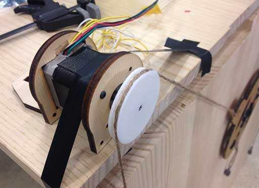
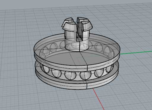
Anna and Geoff led the design of the pulley system, which was modelled in Grasshopper and Rhino. They took measurements from the motor and designed the pully to be close to the same size of the motor. The motor mount design had to be widened by 6mm on each side change because the screws were hitting the pully. The pulley itself had to be changed 3 times because the ball chain wasn't fitting perfectly.
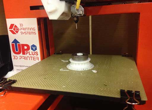
The 608zz skate bearings had to fit inside the gondola as well as the chain holder inside it. We were able to easily hack the pulley design in Grasshopper and add a clip to the top. The first clip broke, so we stopped the 3D printer halfway to insert the bearing and finish the print.
Bridget led the design of the weights on the pulley system. We wanted to experiment with weighting the ballchain on either side as it hangs off the motors, so we designed an attachment for each end of the ballchain, which screws on to waterbottles so that we could tweak the weight easily. The attachment has 3 parts: the screw cap and 2 halves that thread through to encase a short length of ballchain which is held in place by a cable tie.
You can download the ballchain weight attachment files here.
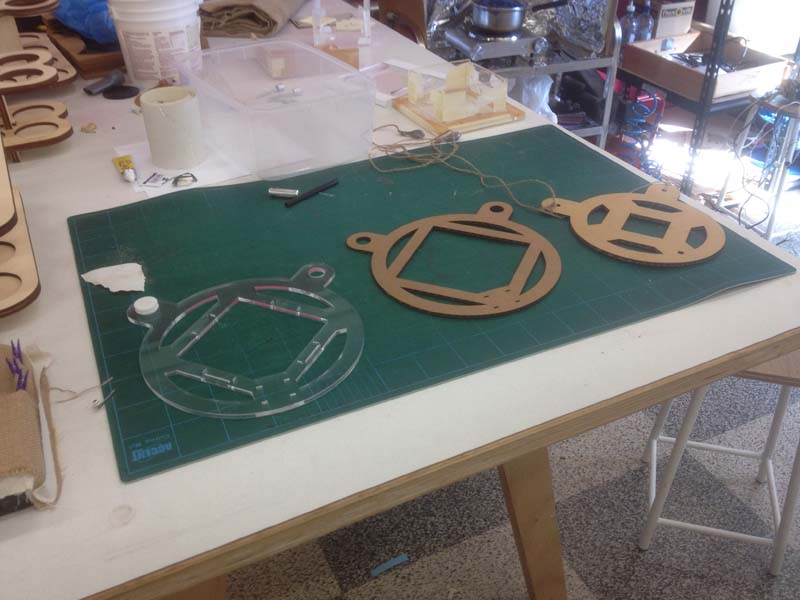
Ben figured out a way to attach the pen arm to the gondola by adding slots on the pen arm so they could be cable tied. Zenna designed the casing in Adobe Illustrator, which we prototyped in cardboard on the laser cutter, and did the final cut in clear acryllic. We had to adjust the dimensions and weight distribution for balance, making sure the gondola was symmetrical so that it would hang in balance from the centre.
Geoff drilled a 3.5mm hole through the water bottle caps to reinforce the strength. Anna recalculated the weight distribution to offset the weight of the chain as the weight distribution changes depending on where the gondola is on the drawing surface. This increased the accuracy of the Scribbly-bear.
Because we grinded the motors, they got hot and de-magnetised. So we replaced the motors with new ones that we grinded using a wet sanding grinder.
Gallery
About the Motor Mount
The motor mounts were designed to give the Scribbly-Bear adaptability to any surface. The design of the motor mount had to take into consideration where the Scribbly-Bear would be placed, the size of the motor and the size of the pully wheels.
Craig and Jasmin led the design of the motor mounts. The part of the mount that attaches to the motor was designed in Adobe Illustrator because it shouldn't have to change over time, while the mounting system that attaches to the wall or the ceiling beam was modelled parametrically in Inventer so that it can be easily adjusted depending on the surface or structure we wanted to mount upon.
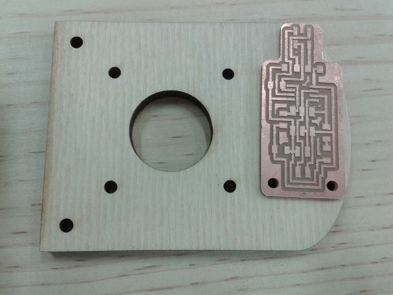
The motor mount design kept changing to give clearance for the drive pully and the roof. When we added the homing switches in, they needed to be far enough down from the ceiling to not catch the pulley. Daniel designed the reflective sensor boards that acted as homing switches.
When testing the motor mounts with the travel mounts and gondola, we found that the Motormounts were not snug enough, so we laser cut small pieces of 4mm ply wood and wrapped it in layers of duct tape to get a snug fit. These makeshift wedges helped stablize the motor mounts.
Gallery
GCode
GCode is what controls the Scribbly-Bear, where it goes. To implement that, we had some firmware that sits on the Arduino and takes the GCode coming from the serial line and drives the motors to move to that position so that it does all the inverse kinematics. One of the cool things of what we're doing is we're using the Michaelangelo firmware as the basis for us, because it was open source, we could mess around it - the servo control pen up and down lift, gives us the flexibility to add multiple pens with small changes to the code. We can update the size of the art space with GCode command so we don't have to reflash the firmware to allow us to move to different surfaces.
We wanted to test accuracy the Scribbly-Bear with a 100 mm x 100 mm box and an image to test its creativity. Jasmin found a free SVG on The Noun Project of a drone delivering pizza.
Evaluation
The Scribbly-Bear is a work in process. In the current iteration, we are happy with the following:
Electronics are good
Motor mounts are effective
Pen holder is appropriate
Gondola fit-for-purpose
Motors are correct
Firmware is solid
Bearings/pivots are super cute
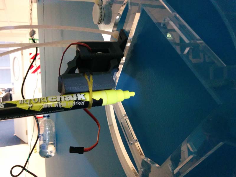
Wet chalk pens work for quick sketches
Homing switches are working
Weight distribution on gondola is perfect
Reduced motor slippage on pulleys
Break out for servo's was good
We are working on making the following improvements:
Improve integrity of printed parts
Tidy wires/improve casing
Add backing to motor mounts
Our Creators
To read more about how the Scribbly-Bear was created, visit: