Designing the Machine
This week was group project time! We have opted to build a large scale delta configuration drawing robot, The details of the whole group project are up here. On this site I will be focussing on the part for which I was responsible, designing and implementing the Pen Lift Mechanism.
One of the techniques I really wanted to try out was designing an entirely print-in-place mechanical assembly using a 3D printer with dissolvable support material. In FabLabWgtn I had access to the Stratasys uPrint.
Design
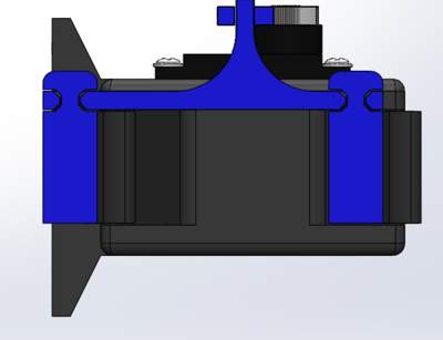
My concept for the pen lift mechanism was to use a 4 bar parallellogram linkage to keep the pen exactly normal to the surface being drawn upon. As I mentioned above I wanted to try and print the bulk of the mechanism in place, to do that I needed to ensure that all of the components have a sufficient clearance to allow for some dissolvable support material to be printed in the gap to maintain separation.
uPrint Limits
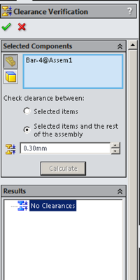
The uPrint prints with a minimum layer height of 254µm, thus I had to maintain at least this separation, to give myself a little bit of wiggle room I upped the clearance to 300µm.
Solidworks has a clearance verification tool to run an automated check confirming that each part has the appropriate clearances, in this case I have selected one of the crossbars and asked the tool to confirm that it has a minimum clearance of 300µm, in this case you can see that it has passed with flying colours!
Strengthening Pins
One of the issues I encountered on my first prototype was that the ⌀3mm pins in the 3D printed hinges were a little prone to breaking right at the joint between them and the body of the part (where is forms a right angle). To alleviate this I opted to put a small chamfer on both the pin and hinge components to spread the load out from the corner.
Design Simulation
Before printing I wanted to be able to test the full range of motion and ensure that no parts were colliding and everything behaved as it should. To do this I assembled the mechanism in Solidworks and used a variety of mechanical mates to constrain the parts to only move in the degrees of freedom they actually had.
Once the constraints were in place I could run a motion study to confirm the mechanism moved as desired, in the study I 'attached' the drive arm (shown as translucent plastic above) to the shaft of the servo motor and gave it a range of rotation to simulate. Then, because it looks cool, I rendered the motion study using PhotoView360 and created the above video
Making the Mechanism
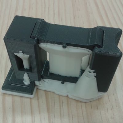
I wound up making 3 prototypes, the image to the left was the first, whilst it worked I found that ultimately my approach of using a small length of wire to connect the 2 drive pins to the servo horn was not the best, the small pins were fast to break and the whole assembly was far less rigid than I wanted due to play in the wire
The second prototype was a failure based solely on my inability to properly use the clearance verification tool resulting in the moving parts of the second prototype being entirely static. Not my finest hour.
Final Prototype
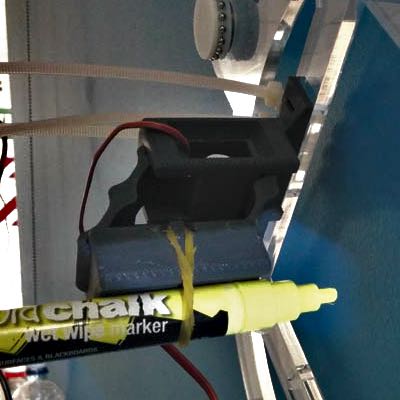
The final prototype worked like a charm, after a good long soak in the support material dissolver it was as simple and slotting in the servo motor, lasercutting out the drive arm and pushing it on to the servo drive spline.
As you can see the pen holder is designed to hold a variety of pens using a simple elastic band to retain them. I had looked at a horde of different, more complex retention techniques but ultimately the simplicity of a couple of hooks and an elastic band won out.
Design Files
- Solidworks design files are available as a tarball here.