Week 15
Assignment - Mechanical design and Machine design
This week we wanted to keep light but also have enough work for everyone to busy for a week. We started with a brainstorm on what ideas and machine that we could build. Craig and especially Daniel had heaps of experience, with Daniel building machines from 3D printers to huge CNC shot bot type machines. Craig was also very knowledgeable in this area with making 3D printers and also having a go at making a draw bot.
We decided as a group that we wanted to make a draw bot, which is a servo controlled machine where the motors are up in the corners and it is controlled with a pen on a gondola. The gondola is attached with a line to the motors and depending on which motors turn in either direction the gondola can then have a pen attached which draws on the walls .Very similar to this image.

We went out to the whiteboard as a group and wrote up some ideas about what we thought were necessary and what could be added on features at a later date.


We then divided the different tasks between us. I was working in the group with Craig, Jasmin and Anna sorting the motor mounts and pulley systems we were going to create. Me and Anna worked together really well were we could bounce good ideas of each other doing quick sketches talking about ideas before making it on Grasshopper and Rhino.
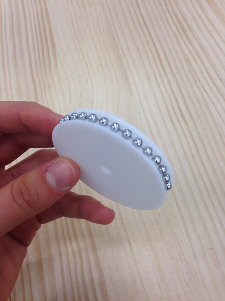
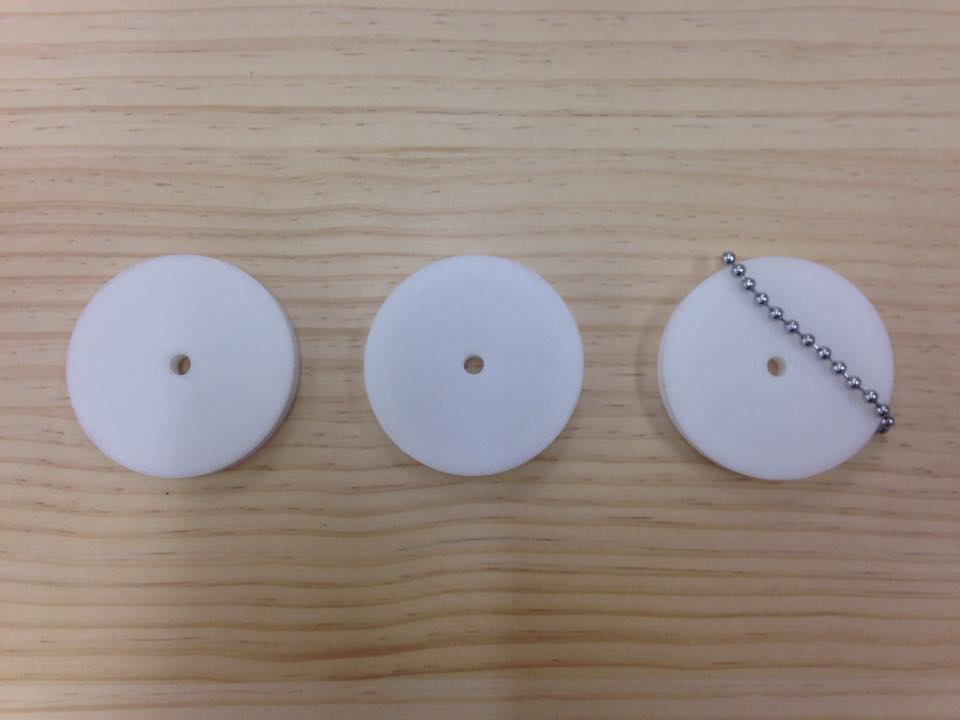
This photo below shows us testing how well we had measured the gaps in the shower chain that we were going to use. Because the chain was going around a curve they were stretching out more than we thought and needed to do a few 3D prints to get it to work how we wanted.
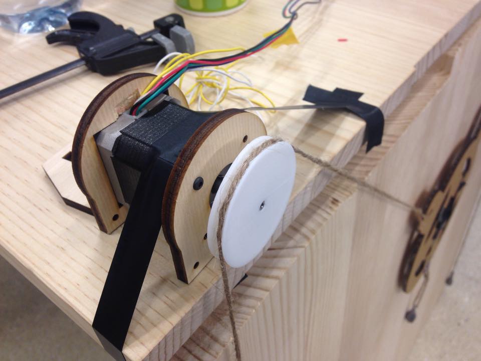
The other problem that we encountered was that when we slid the 3D printed pulley onto the motor shaft with the weights attached when we were testing we found that the shaft was slipping inside the 3D print. To solve this we had a few options, we could make a grub screw type design very similar to that of the MDX-20, we could glue the 3D print to the shaft. Another idea was to file down the side of the motor shaft so it made D shape and then adjusted the 3D print to that it could slide on a perspective way and would not spin. This did fix the problem and made it a lot stronger.
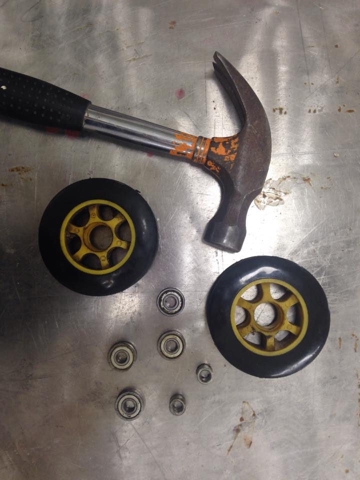
The next thing me and Anna worked on was the fitting between the gondola and the chain, the pulley system on the gondola. We first thought because we made the first pulley on Grasshopper that we could quickly adjust that to make it smaller. Because this part of the machine would have a lot of movement up and down we thought of a way to decrease the friction between parts and thought we could use some small ball bearings 608ZZ type skateboard bearings. We asked Wendy and she had some old wheels lying around that had been used for a trolley and were perfect for what we wanted. Me and Anna went into the workshop and banged the bearings and used these as the dimensions to create the next smaller pulley from.
We made a cross type on the top of the print so that it could click into the ball bearing. But in trying this, because it was so small and the little pins would always snap.
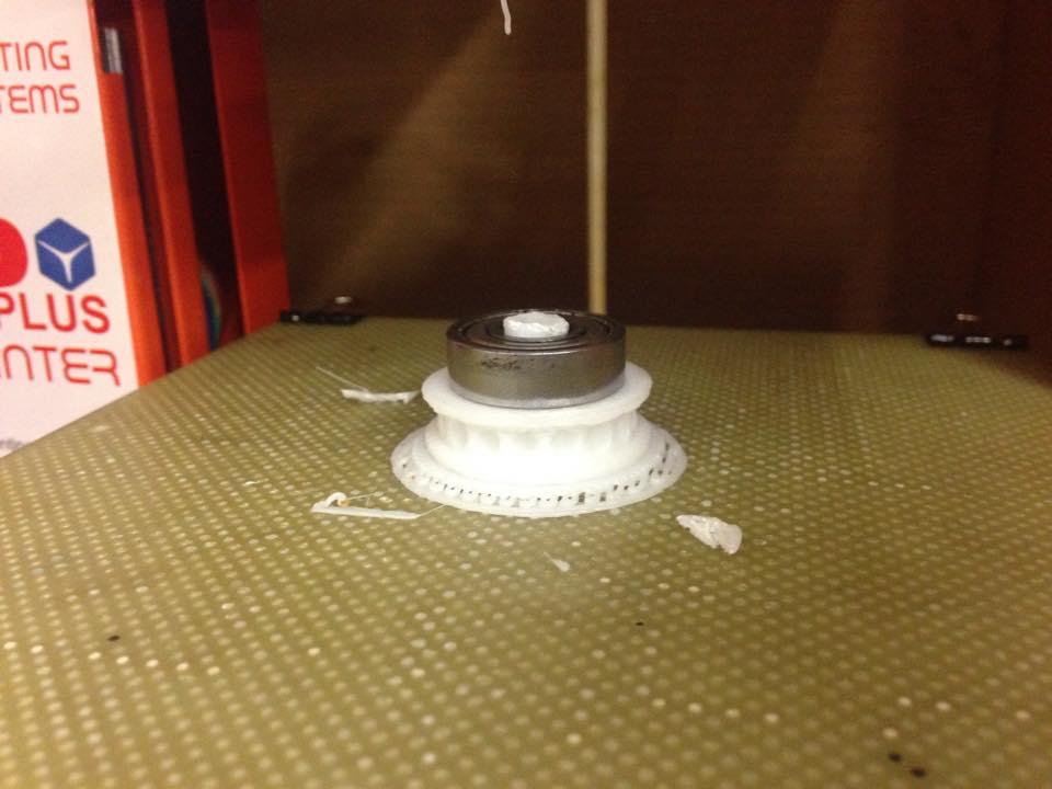
We came up with an idea and something I wanted to try since we started using the 3D printer, to try and insertion print where we would quickly stop the printer and insert the bearing into the print and then continue the printer and print over the top of the bearing to lock it in place with the plastic. Craig showed us how we could pause the print at a certain height on the Z axis so we could get the timing perfect.
When we tried the first print when we inserted the bearing into the print it wasn't sticking at all to the bearing and not bonding to the other plastic very well I thought it could be because it was not hot enough so we tried heated the bearing with the heat gun and it worked heaps better.

This photo shows the bearings inserted into the gondola where the metal part of the bearings was in contact with the acrylic, Ben made it so that the hole was the exact size of the bearings and because it was 6mm the hole was slightly bigger on one side so that the bearing could be wedged in tightly and then the other side sat about 1mm of the surface so that the face of 3D print wouldn't rub on the acrylic, this worked perfectly like we expected.
We also made an awesome webpage about how the whole documentation process went with everyoneŐs inputs on how we all made this machine come alive. The website also has videos showing the Draw bot in action and which things worked and things we could improve on, I would highly recommend checking the page out.
The Scribbly-Bear Machine WebpageFinal Mechanical Thoughts
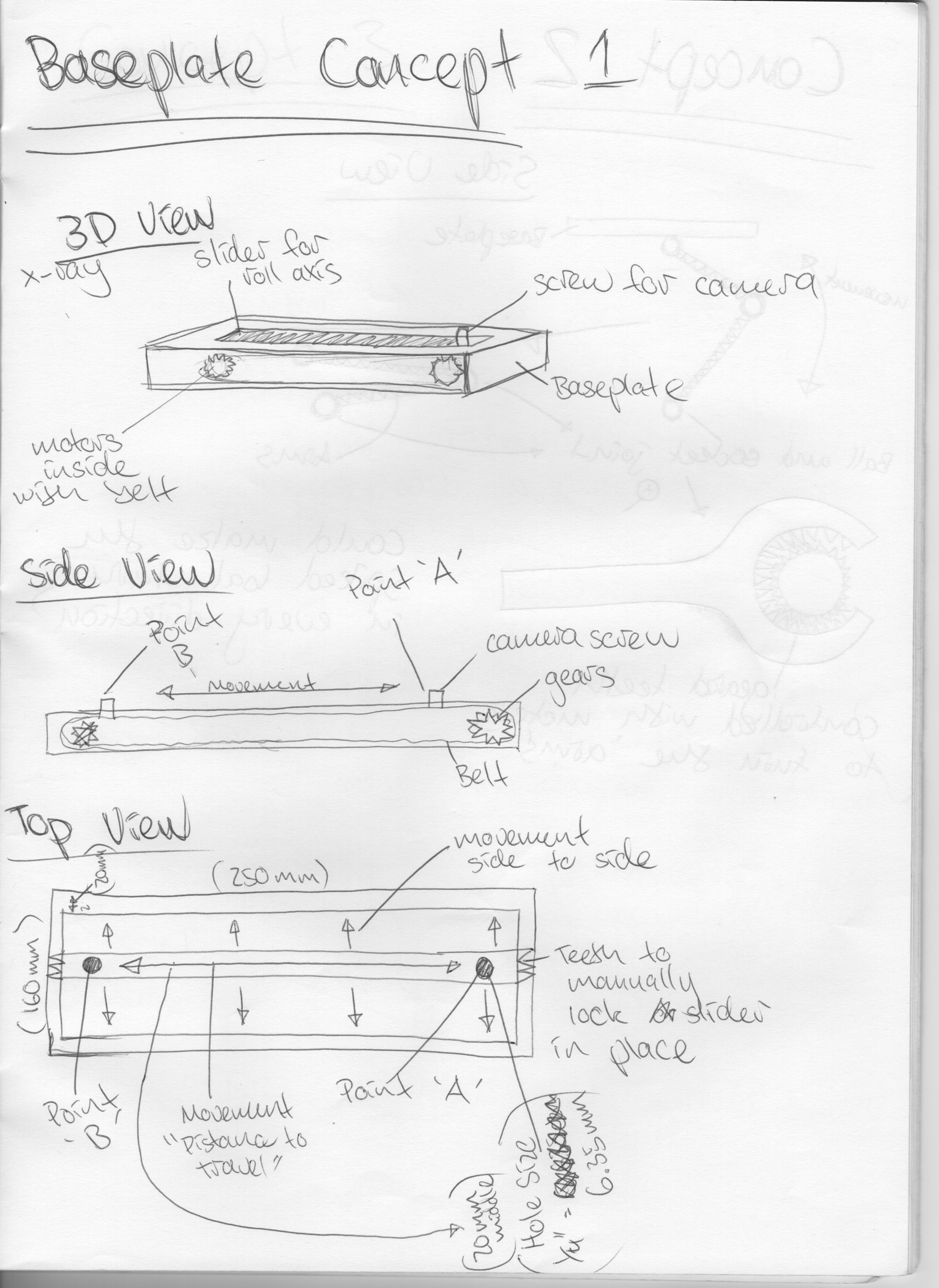
I thought about how this would be able to help me with my final project and I was really wanted to explore how a rack and pinion configuration worked. How the gearing worked and how when spinning could turn objects and drive objects in different directions. I had originally pictured this from the first weeks where I had a few drawings about how I thought it could work. In my final project documentation I go into more detail about how I got the rack and pinion to work and function and why I used it instead of other movement methods.