The Babedunio
A group fabricated Fabdunio built for the electronic needs for our final projects.
Me and Ben had already given it a bit of a shot at making a Badunio - which is double sided board using a Attiny44 and we didn't have to much success. Ben may have progressed further and could check his blog, but I didn't spend much more time on it.
Part of the Fab Lab diploma was to make a working fabdunio so we decided as a group to make it together and to make it so everyone could use it for there final project. Me, Jasmin, Ben and Anna worked to construct this piece of equipment. We all thought how awesome it looked and decided on a name Babedunio.
We wanted the Babedunio to be like the Ardunio Uno with a 20mHz resonator so me and Jasmin could control small servo motors. We started by looking at the example fabdunio boards and what other people from previous years had made and the components they had used. We made up a list of the components we needed.
- ATMega328P
- 20 mhz resonator
- 17 In/Out's - both Analog and Digital
- Filtered and unfiltered VCC In's
- Switch allows you to flip between using a battery (filtered) and the FTDI (unfiltered) for power
- RST Button
- 4 GND's
- 4 VCC Out's
- LED for power
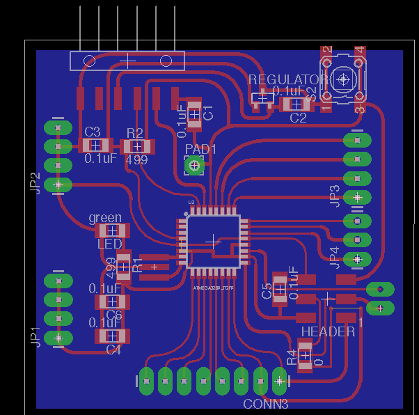
VERSION 1
Anna designed the schematic, Ben did the rats nesting, and I made the board pretty by making it smaller, and adding curves to the traces.
MILLING & STUFFING
After we milled the first board and Anna stuffed the board, Ben noticed that the regulator was not connected to VCCIN. It turned out that Anna had connected the regulator to the FTDI VCC, and not the VCCIN.
Jasmin took on the challenge of "franken-fixing" the board with some wires and it checked out on the multi-meter. Anna burned bootloader and we used a breadboard to connect the Babeduino to an LED and resistor in order to test whether or not we could program it.
When we tried to upload some LED blink example code to the Babeduino. we saw this error.
Craig pointed out that we were using the wrong boardfile, and sent us the ATMega boardfiles. We followed the readme.md instructions and re-started Arduino IDE and were able to see the ATMega in the Boards menu.
Anna connected Pin 2, but when the program did not work, we looked up the ATMega328P pinout board, it turned out that the way we routed the board, we didn't have Pin 2 connected to anything. To correct this error, we connected the LED to D5 (pin 5), and the program worked!
There is an awesome video of this working on Jasmins Blog!!
Jasmin also mentions in her blog some of the other problems that we encounter while trying to get this difficult piece of equipment working.
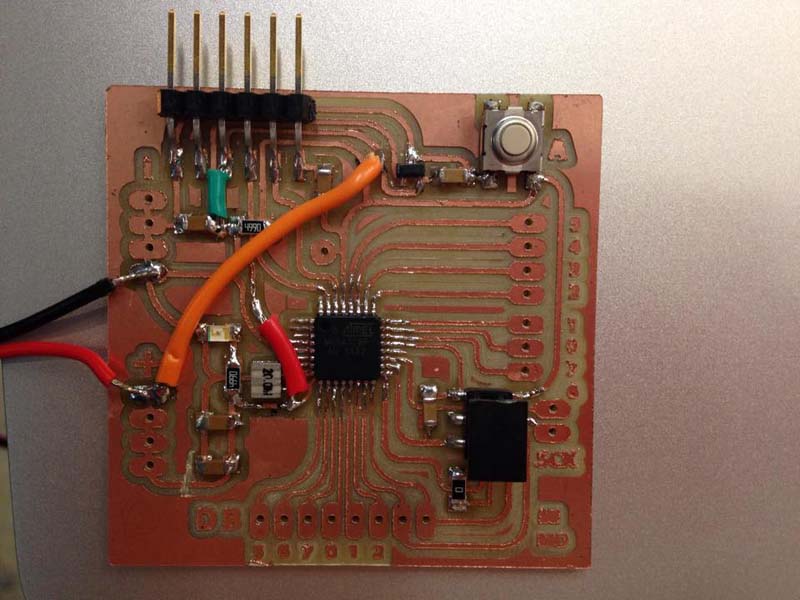
We ended up re doing the rats nest so that we didn't need to use and wire and I also made it so that the legs on the atmega were a lot longer so it was easier to solder and drag the solder out on the copper.
Here is the final Babedunio milled and soldered up and working with servo motors and LED, I show the use of this in my final project documentation.