Final Project
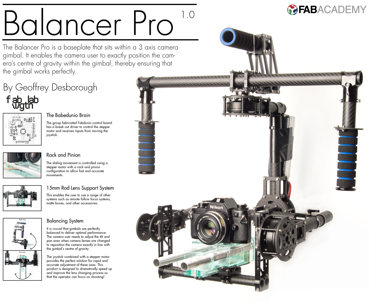
Balancer Pro Concept Statement.
The Balancer Pro is a baseplate that sits within a 3 axis camera gimbal. It enables the camera operator to perfectly balance the cameras centre of gravity within the gimbals. This is a vital element to making sure the gimbal is working as,it should to stabilise the camera along all three axes of movement.
It is fabricated from laser cut 3mm clear acrylic, and uses 15mm aluminium rods. The rods are used for a lens support system which enables the user to attach a range of other systems such as remote follow focus systems, matte boxes, and other accessories. The rods are a crucial element to keeping the sliding movement parallel.
The movement is controlled using a joystick which sends information to a group fabricated Babedunio which then interprets that information to make the stepper motor drive the rack and pinion configuration. The joystick combined with a stepper motor provides the perfect solution for rapid and accurate adjustment of these axes.
It is designed to be compatible with most of the existing gimbal products in the market. It could be sold as an accessory or used directly by one of the existing manufacturers if compatible with their software. This product is designed to dramatically speed up and improve the lens changing process so that the operator can focus on shooting!
Background Information about Myself and Photography
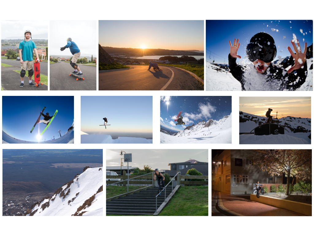
Last year I completed a Bachelor of Design majoring in photography. A strong theme in my studies was action sports photography. For my final project I produced a 140 image action sport magazine which featured eight athletes in a wide range of different sports including BMX, long boarding and snow sports. All of these were shot in demanding environments for the camera operator. I was following snowboarders into 40+ foot jumps with my expensive camera relying on my skills not to crash. As a trained ski instructor I was able to accomplish this but the difficulty of shooting in situations like these and the high risk to equipment got me thinking about how action sports photography could be achieved more easily.
I was taking Industrial Design papers throughout the course of my degree and became interested in this area of design. In my final year we were able to design and create our owm project and I looked at the possibilities of building something to house and protect my camera when shooting in these difficult environments. From my research on existing housing and protection for cameras of similar size I could see the emergence of 3 axis camera gimbals. This equipment balances the cameraŐs centre of gravity within a gimbal that can rotate in terms of tilt, pan and roll. Using gyroscopic sensors and brushless motors the camera is electronically stabilised so that it keeps a level horizon and dramatically reduces the vibration transmitted from the operator to the camera.
I wanted to improve on the design of these gimbals especially in the area of protecting the camera while still utilising the rapidly developing technology of stabilisation with brushless DC motors. I worked on this project for a semester last year and managed to do some early prototyping. I intend this to become my Masters project and I wish to push my designs further this year.
The idea behind my Fab Lab project was that I could create a self-levelling baseplate that would be compatible with a gimbals already on the market and be a crucial part of my design that could be incorporated in a full gimbal design.
Research
There a large number of different gimbals on the market aimed at different uses. The most common is for aerial photography but they are also used for shooting from vehicles and hand held. An example of a pioneer in this area is Shotover Cameras in Queenstown. Where at first the gimbal was in a specific housing attached to a helicopter with a camera controller and another operator inside the helicopter, with an external screen and the ability to move and focus the camera. These systems were very expensive and cost 100s of thousands of dollars to make and were very expensive to operate. When the controllers and motors for these systems started becoming much less expensive and smaller device wide range of models came onto the market that were small enough to be hand held with a single operator, and even attached to remote piloted aircraft systems (also known as drones).
There is therefore a huge market for these gimbals and specifically the ones that are lower cost and able to be adapted to many different situations such as use on a drone, attaching to a handheld system, and attaching to a cable cam. In some cases this might all be part of one photo or video shoot. Each of these different shooting methods have their place in producing exciting content. However they would all benefit from lightweight, easily used equipment that gives better protection to expensive camera equipment.
The Design of the Balancer Pro
Design Criteria
- incorporate a 15mm lens support system
- compatible with a wide range of gimbals
- small in size, compact and lightweight
- easy to control and use with simple intuitive ergonomics
- have a strong locking mechanism when the camera is balanced
- lightweight and strong materials, maximising the benefits of their properties and how they could interact with other materials such as aluminium
- connect to the camera easily
- keep the centre of gravity of the baseplate as close to the camera as possible
- high level of aesthetics and coolness factor (e.g. use of carbon fibre)
Design Details
The aluminium tube was milled out using the milling machine in the 3D workshop and uses slots that operate as a locking mechanism.
It was critical to make sure that the teeth on the gears lined up exactly. The motor was held in place with 25mm M3 screws and the box that held the motor was also held in place by the support rods making sure that they were always lined up perfectly along the whole length of the movement.
I also made sure that the rack was secured and wasn't going to move. I made a slot 4mm from the end so that it could slide and lock into place when the rods were inserted. This worked really well and I replicated this on the front so that it was locked from both ends.
I also created a slot type system that the back pieces would squeeze together and then slide down into the bottom piece of the baseplate where a drop of glue would be able to hold it securely in place without any movement.
that the design includes manual adjustment for the camera on the top plate. This top piece also had slots in it so the box stays square and the rods do not rub and cause unnecessary friction.
Mechanical Design
I wanted the baseplate to have a moving mechanism that was controlled using a stepper motor. There were a number of different motorization options I could have taken;
- worm gear configuration
- rack and pinion
- motors with a drive belt
The worm and gear was my first preference because it would have a really high torque and allow fine adjustment. The downsides were the time and expense needed to 3D print the worm, the size of the gear would be small, and combined they might not be strong enough to hold the necessary weight. These factors made me rule out that option.
Using two motors and a belt in the same way that consumer-grade printers work was something I also considered. For this option I would need to include two motors or some type of free spinning gear at the one end of slider for the belt to go around. Another negative was that the motor would be some distance from the cameraŐs centre of gravity. This was a really important factor, to make sure that the baseplateŐs centre of gravity is as close to the camera as possible. So I didnŐt pursue that option.
In previous projects I had used rack and pinion drive and I had a reasonably good understanding of how they worked, in particular spur gears. And also very importantly I knew that I could get them into vectors on Illustrator that could be then used for laser cutting. There are a high number of these free gear generator websites available now and I had used these websites before and found it to be very good;
There are a high number of these free gear generator websites available now but I had used this website before and found it to be very good;
Gear GeneratorYou are able to create the size shape, tooth count and number of different variables so that you can make a perfectly suited gear configuration for your needs. These files can be downloaded and simply dragged and dropped into Illustrator to be then scaled down into smaller stroke sizes so the laser cutter can read them. So this was the drive option I used.
Electronic Design Criteria
- needs to run a stepper motor with a 12v input
- needs to have an input device such as a joystick or a slide potentiometer
- the electronic components must be very compact
- the motor needs to have sufficient power to move the camera and lens
Electronic Features
First I wanted to make the slide potentiometers work with Ardunio so that I could see and read a value on the position backwards and forwards. The slide potentiometer operating principles are;
A linear taper potentiometer (linear describes the electrical characteristic of the device, not the geometry of the resistive element) has a resistive element of constant cross-section, resulting in a device where the resistance between the contact (wiper) and one end terminal is proportional to the distance between them. Linear taper potentiometers are used when the division ratio of the potentiometer must be proportional to the angle of shaft rotation (or slider position), for example, controls used for adjusting the centering of the display on an analog cathode-ray oscilloscope. Precision potentiometers have an accurate relationship between resistance and slider position.
Wikipedia PotentiometerIn short this means that it can signal changes along the length of the slider by the amount of resistance that has been created. I could see that this was going to be much more suitable for my final project than the joystick I had originally considered. A joystick has two axes of movement that are not needed at this stage but could be something that I looked into further down the track.
In my code featured below I changed a few things so that the reading from the slider was between 0-100 just to make things simpler when confirming how things were working.
Below is a video of the code and the slider working, this is just before I changed the output value, it is still at 0-255 in this video.
Stepper motors
Next I wanted to incorporate a stepper motor, This would provide a high level of accuracy rate and could respond to very small steps so that I could use it to position the camera precisely. They work by opposite coils in a circle charging themselves to rotate around in a series of pulses in both directions.
The Fab Wgtn inventory of motors were large and heavy, so I found some more suitable motors at a local electronics retailer. They had a small stepper motor which had about 700grams of holding torque, which I felt would be quite important as it would be able to hold the cameraŐs weight if it was placed in a vertical position.
Jaycar Stepper MotorThe supplied data sheet was helpful but I managed to find one online that had more specific details.
I couldn't just plug this into my Babedunio to make it work because stepper motors require driver break out boards. These boards work by attaching the motor to specific pairs of coils on either side of the circle so that they can be charged in a way that will make the motor spin. Another benefit of these boards are that they are able to break down the steps into as small as 1/16 steps, which will increase my accuracy of movement.
I used a Pololu Stepper driver motor board, the same as this;
Pololo Stepper Driver BoardI found a datasheet for it so that I knew how to wire it up on a breadboard.
I wired this up using a breadboard and some jumper wires. I tried a few different codes that were included in the Arduino Library but these just made the motor vibrate and not rotate properly. With some assistance from Craig I was able to get it to work using coding for the scribbly bro stepper motors.
Below is a video of it working with some fab lab stepper motors and the motor that I intend to use. Note that I am using a ****** DC power supply which controls the voltage and the current is pulled when it needs it. I intend to make this with a battery for future prototypes so that it doesn't need to be connected to the wall.
Once I had these working I wanted to test how well my gearing system worked and how many steps would be involved for the movement of my slider. I had a minor issue as my gear piece didn't have a grub screw or something to firmly hold it against the motor shaft, so I just used hot glue as a temporary solution. This did work pretty well and here is a video of the sliderŐs first movements:
Next I wanted to combine the slider and the stepper motor so that the stepper would move when the slider was pushed. Craig helped me with understanding how each of the codes that I had written needed to be combined in a way that would work for the solution I wanted. When programming I needed to calibrate the stepper motor board so that it was running the right amount of current so that it wouldn't get hot and skip steps, so I reduced the current to 0.4 volts using the voltage meter and a small screw driver.
I had few problems with connecting up the correct wires to the pins on each of the boards but once I had sorted those problems and got my code working how I wanted it to it FINALLY WORKED!! I was super happy and took several videos of it working!
Here is a screenshot of the working code which is in my downloads file.
One option that I took when making sure this proof of concept worked was to use a breadboard. This was a working prototype and my thoughts about this concept were that the other control board parts such as the Babedunio, stepper driver board and the slider would be fastened somewhere onto the gimbal and wires would run to the baseplate to control the movements. The picture below does show where I would intend to mount the slider if I was to make further models. Also the picture on the right shows the use of hot glue to hold the gear to the motor shaft, this would also be developed using a grub screw or some type of D type design that was similar to what I had used during machine building week.
3D Design
I have also modelled this prototype up in solid works so that I have 3D representation of the model and is in my download files. I found it easier to work in 2.5D with illustrator when using the laser cutter but doing a 3D model did help with some slider aspects.
What worked and what didnt?
I think I was successful in producing something that I envisioned right at the start of the Diploma and executed it exactly how I wanted. I managed to make a device that will fit inside a number of different camera gimbals and will be something that the gimbal operators would be hugely excited about. I am hoping the Balancer Pro will be able to help the camera operator save hours and hours of rebalancing time and really be able to focus on the job at hand.
I don't think I had things that I would say were unsuccessful but I would definitely say things needed to be improved and refined . The baseplate would be able to operate better and much more efficiently with a few design tweaks, some more added features and different materials. I talk about these in more details in my future development.
What you learned?
I have learned a huge amount through this Diploma and especially with my final project. The most challenging part for me was the electronics. I had a rough idea how things worked and initially thought that it could be hard to learn, and I did find it difficult. Having done industrial design I was confident with physical object problem solving, for example when I was making my baseplate, how my rack would slide and lock into place. With electronics I felt that when I got stuck I didn't really know where to look, I would search problems on Google and read through forums often creating more questions that I originally had. I did however towards the end of the Diploma become much better at this and been able to read for example code for specific problems and see what they have done to get around some of these problems.
I also learned so much about each of the machines and really wish I had more time to fully exploit more of the features they have to offer. I often said to Wendy and other class mates when we were completing the Diploma that we could easily spend a month on some of the machines such as the Shot Bot, laser cutter and MDX-40s. I feel I really only scratched the surface for what was possible with these machines.
For further development I look to explore;
- The use of advanced materials such as different machined alloys and plastics to improve rigidity, price, weight and the aesthetics of the product.
- Electronic controls that could be run remotely e.g. using a smartphone app
- Integrated software that could work a range of different gimbal softwares
- Look at a better way to reduced friction along the 15mm rods so that they have a longer life.
- Some type of gyro sensors inbuilt that can detect if the camera is perfectly balanced a can work with the motors to perfectly balance the unit
- Investigate more ways of locking parts together without using glue and using stronger fixings.
- Have a grub screw of D locking design on my motor shaft toehold the gear in place, similar to what I used in machine week.