Goal
My goal for this week is to make an intelligent optical reflective sensor for my final project. The sensor will be based on the concept of synchronised sensing as described in the lecture.
Specifically, I want to use this sensor for the detection of parts within my component dispenser system both for stock checking and for confirming that a part has indeed been dispensed.
Design
Components
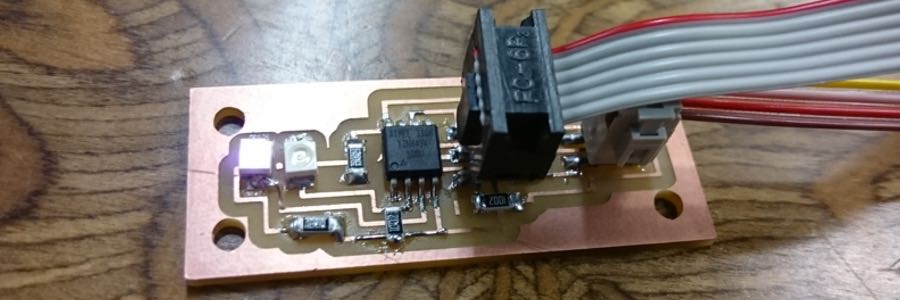
The Sensor-LED pairing is the matched set of the Optek OP580 Phototransistor and the spectrally matched OP280 IR LED, this means that the phototransistor is most sensitive to light in the same part of the spectrum that is emitted by the LED (in this case Near Infra-Red at 850nM).
The Microcontroller I used was the ATTiny45 running on it's internal oscillator at 8MHz, I chose to use the internal oscillator rather than an external resonator or crystal as it allowed me to further compact the board design and I am very keen on keeping the board as small as possible. The major drawback to using the ATTiny45 is the lack of a dedicated I2C/TWI controller (The protocol I want to use to communicate between sensor and actuator controllers in my final project), the ATTiny45 does have a USI controller which can behave as an I2C/TWI controller however I need to do more research (and consume a lot more caffeine) before I can properly implement this functionality, for now I am using software serial for communication.
Testing
Issues
The joys of late night electronics design have gifted me a myriad of issues to recount in this archive, the first was my failure to include a current limiting resistor for the LED, this was fortunately recognised before I powered on the board and thus no semiconductors were relieved of their magic blue smoke.
The second issue was my failure to include a pull-down resistor between my sense line from the phototransitor and 0V, thus my exclamations of "It can't seriously be that bright in here" were resolved with the simple addition of a 10K resistor.
My final embarassing failure was that of not considering the voltage-sagging capabilities of a relatively powerful LED and failing to include a power smoothing capacitor, I became aware of this when the board would function perfectly until I disconnected the AVR-ISP programmer, thus removing the stabilizing influence of it's capacitors and putting my board into a state of electronic seizure.
Programming
As mentioned on the Electronics Design page, I chose to program this sensor using the Arduino environment in order to create a relatively simple setup I could use as a teaching tool for an introductory μControllers class I run.
The first step was to check the response time of the phototransistor, the datasheet puts the typical rise/fall time at 15μs, meaning I would need to wait at least this amount of time between toggling the LED and performing a read. The conversion process on an ATTiny44 takes 13μs, this means that coupled with the time to actually perform the analogRead using the rather slow Arduino libraries no manual delay is needed in this environment however we are limited to a maximum sensing rate of roughly 5kHz.
Next comes noise reduction, I wanted to exclude noise initially through the simplest means possible which meant oversampling the data and then normalising, I chose to first do this simply by taking the mean of n samples. For my test program I chose 10 samples giving a maximum sensing rate of 500Hz.
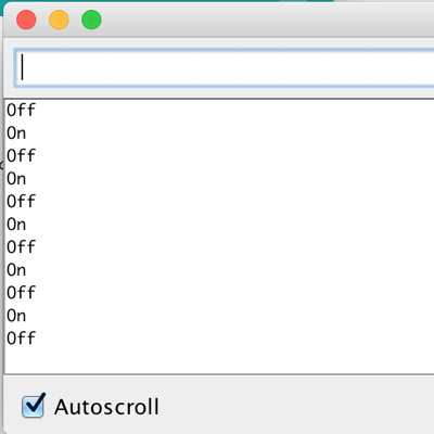
Once I had the normalised Δ value from the synchronised sensing it came time to set a threshold, I experimented by piping the calculated Δ value out over serial and choosing a value based on my desired proximity setting, I wound up selecting a value of 100 (which equates to just shy of 500mV with the 10 bit ADC). I could now do whatever I pleased with my boolean result, in this case for testing I sent the simple strings 'On' and 'Off' over serial whenever the state of the sensor changed.
Design Files
- The original Eagle design files are available for download here.
- The library I created with the Optek parts in it is here.
- The Arduino-based sketch used for testing is here
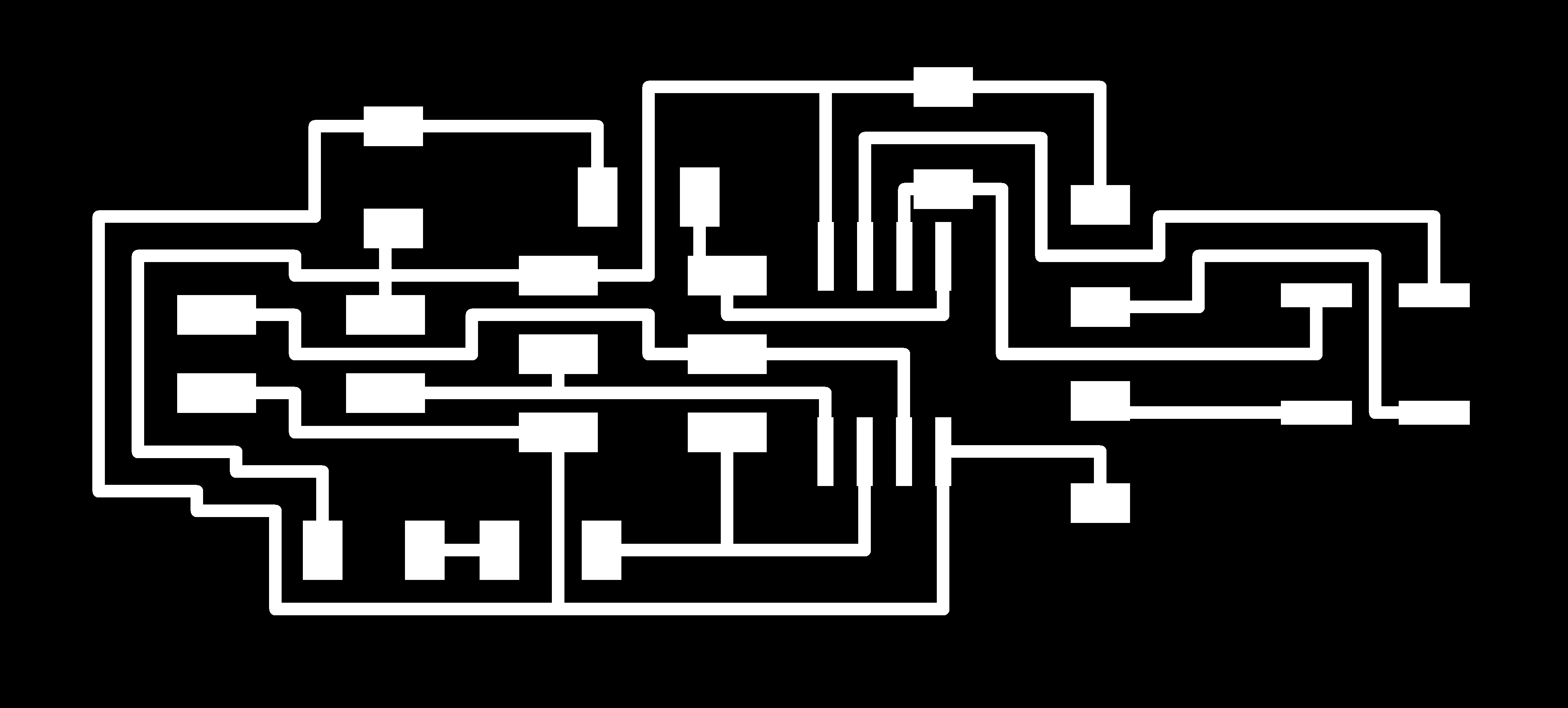
- Images ready for milling: Traces and Cutting Out.