Molding and Casting - From one to many
The challenge:
Design a 3D part to case. Machine a hard positive mold. Cast a soft negative mold. Cast the final part(s).
Plan of attack:
Design a simple object in CAD to encase my circuit board. Go through the three step casting process and successfully encase one board.
Approach:
Have a play around with casting. I have no experience with it, so successfuly making an object will be awesome. There is the possability that my final project will include cast components if these tests go well. Im quite interested to see what the asthetic and tactile results of the cast objects come out like. Im also quite keen to try out insert casting by encapuslating a curcuit board inside my object.
Molding and Casting - Making the block
Melt down an unneeded wax molds to recast into a block.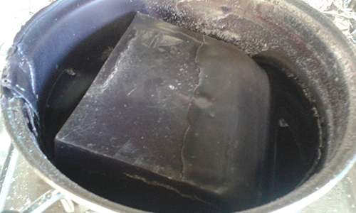
Do it slowly and with extraction. Using a medium heat for a long time, without stiring, seems to give the best results. Unsuprisingly blocks take longer to melt down than shavings.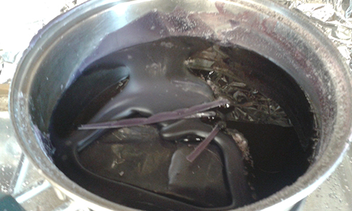
Avoid letting hot wax come into contact with your skin, use gloves and saftey glasses.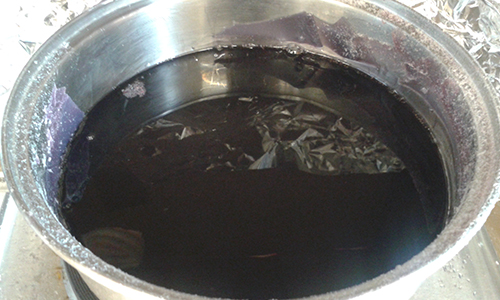
Preheating the mold will allow the wax to flow more easily.
See notes below on mold temprature and pour speed.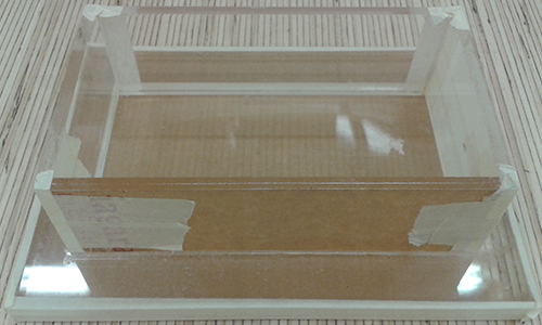
Pour the wax slowly through a fine beed to help prevent introducing air bubbles into the block. My block had some small strands of unmelted wax that could of been avoided if heated through for a little longer.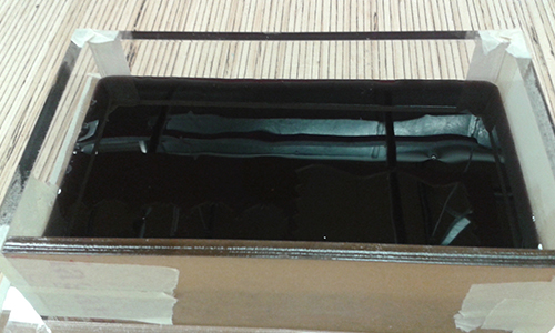
The wax will start to cool from the edges then slowly spread to the middle. Leave it overnight to cool fully before machining.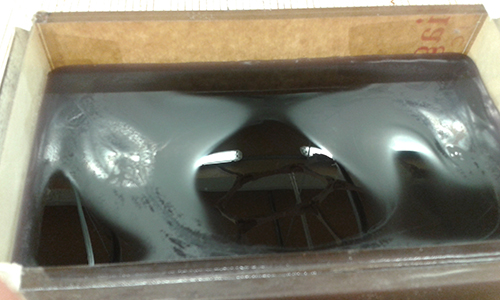
The wax will also contract slightly as it cools creating raised edges around the outside. If the wax cools to fast the block may even crack.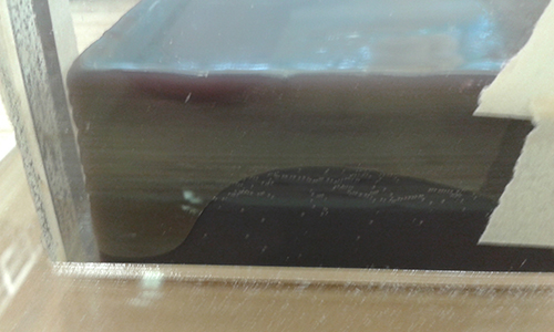
The block turned out well, though I probably could have poured slightly faster and avoided the corners lipping.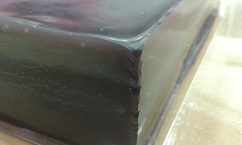
Remove raised edges prior to machining to save time and reduce the strain on the milling bit.
Molding and Casting - Meanwhile in Inventor
While this was going on Id been busy continuing my adventures in parametic modeling using inventor. Im still in the process of learning it so wanted to focus on making a simple mold to test the workflow. Inventor has a couple of neat features that make some mold making tasks really easy. Like adding draft angles.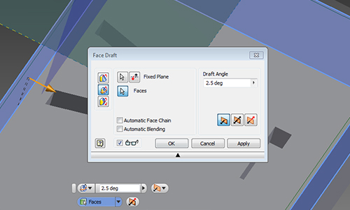
Plus because its a parametric tool its easy work on both halves of my mold at the same time.
Inventor also has a whole mold making mode. It looks like it could be really powerful but seems geared towards creating negatives for injection molding, rather than the positive required to complete this weeks challange.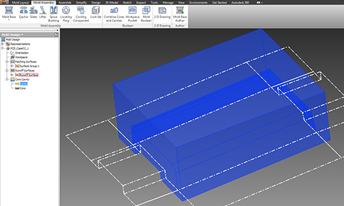
Molding and Casting - Milling with the MDX-40
The MDX-40 are pretty straight forward to setup. Like most 3D processes in the Fab Lab they take an STL file as an input and produce a toolpath from it. Toolpath generation in SRP Player involves working through the menus from the top to the bottem, selecting the tool, speed, cut area and contour stragety.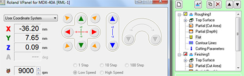
The files exported from SPR player can then be qued up in Vpanel and run.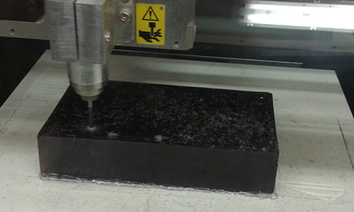
I used a 1/8” 4 flute square endmill to do the inital roughing an finishing path on my block then swapped down to a 1/32” for the final surface detail.
The toolpath for the mill gets a great surface finish by milling across the X and Y axis.
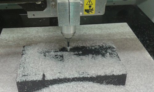
It also allows cropping of the milling area to do even finer detailed finishes.
Machining speeds were:
Roughing
Feed Rate: 720 mm/min
Spindle RPM: 9000
Cut depth: 1.8 mm
Step Over: 1.91 mm
Finishing
Feed Rate: 300 mm/min
Spindle RPM: 10000
Cut depth: 0.1 mm
Step Over: 0.08 mm
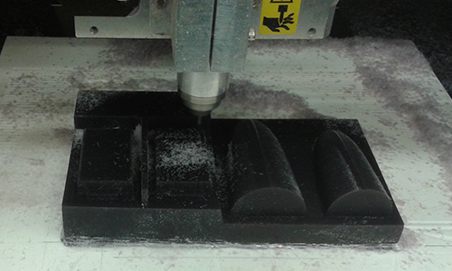
Molding and Casting - The importance of walls
After successfully milling out my wax positive two pretty obvious but rather crippling flaws we’re pointed out to me. To save on machine time and space I hadn’t created walls for half of my block. Meaning I would need to strap something onto the side of it, which would likely leak or leave a lip when cast, making the two part mold unusable. The lack of locator pins would also make lining up the two parts once the PBC was inside them unnecessarily challenging.
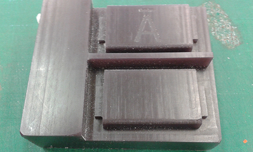
Luckily because it’s wax we can just melt it down and try again!
The new version of the model attempted to resolve my previous issues and introduce some improvements as well. Ensuring the were walls present and high enough above the surface of my object to give the silicon mold some strength. Introducing an air hole to try and reduce the chance of bubbles being trapped in my final object.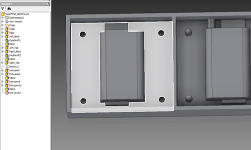
During the regional review we had a good chat about the various speeds that different people had tried milling the wax at. Ours seemed to be pretty standard but a few people had produced nice results at slightly faster speeds. So for the new mold we upped the feedrate from 720 to 900 mm/min. The speed up shaved about 15% off the total cut time and produced a mold of very similar quality.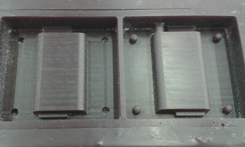
Next up it was time to start some casting. The first step to achieve this was to work out how much silicon my part would take. The advanced properties tab in inventor has a bunch of useful information about the part including its volume. Unfortunately inventor can only give me the volume of the positive part thats been milled, not the negative part I actually want to cast. To work this out we take the volume of the block and subtract the volume of mold.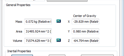
With this useful piece of information in hand we can now consult the datasheet for the silicon that will form my flexible mold. The key bits of information im after are:
Fluid density - 1.15 g/cm^3
Viscosity - 15000 mPa s
Mix ratio by weight - A10 : B1
Pot life - 150 min
Curing time - 6 hours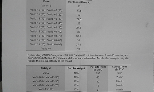
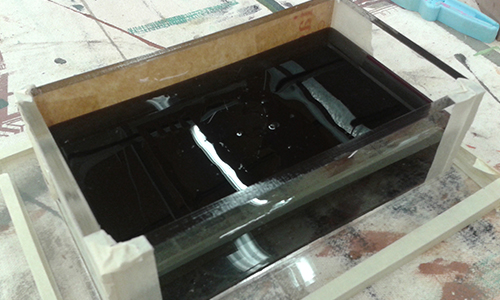
Carefully add parts A and B, mix together and degas in the vacuum chamber.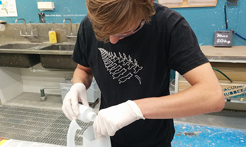
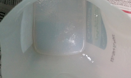
The silicon has a viscosity of 15000 micro pascal which means it pours very slowly and resists sinking nicely into small details like my locator pins.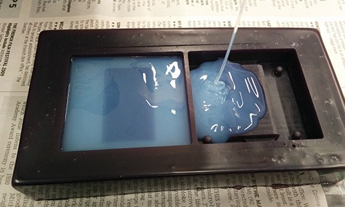
The silicon is left over night to cure.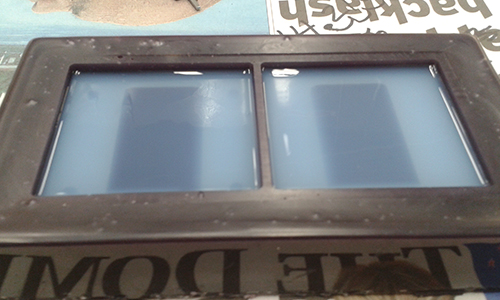
The mold has a three degree draft angle around all the edge to make it easier to demold. And comes away without any significant effort.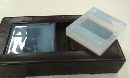
I was really concerned that the viscosity of the silicon in combination with the small size of the locator pins would prevent those details from coming out. But luckily most of the details came out ok.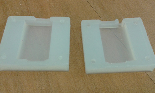
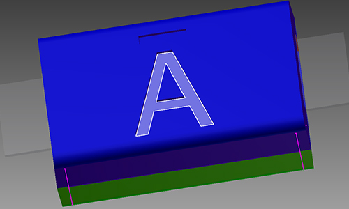
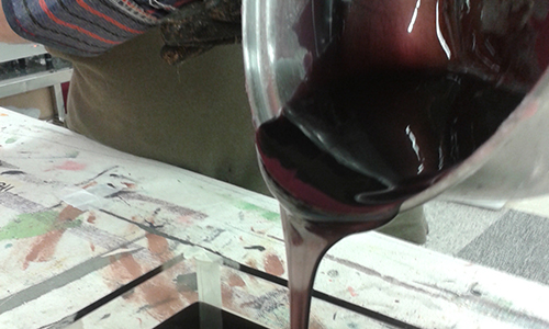
To do the final insert part in polyurethane the process is much the same. The key differences are that this time we choose to add a little bit of violet pigment to colour the resin. As little pigment as possible should be used to avoid upsetting the A:B mix ratio. The pigment is mixed in with part A before part B is added to it to get an even spread of colour.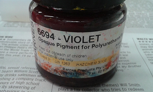
The mold was quite flexible being made of silicon so I reinforced it with some scraps of acyclic and held everything under a little bit of tension with some rubber bands.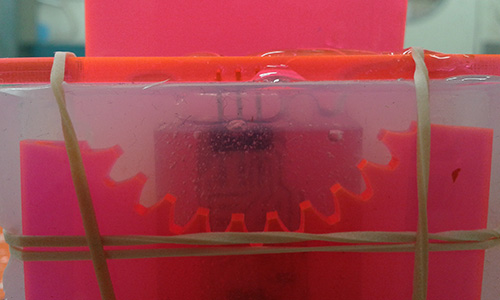
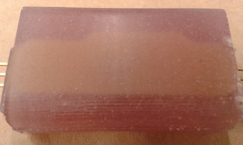
The finished part with my PCB housed inside it.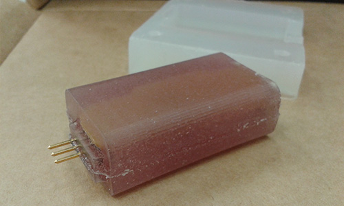
Mold temp and pour speed:
Initially when pouring the wax block my the technique was to pre-heat the mold then pour quite slowly, trying to avoid introducing air bubbles. The second time around I tried the opposite pouring much more quickly into a cold mold.
The results were quickly apparent, the faster pour stopped the lipping effect on the corners and the cold mold caused the edges to cool much sooner giving crisp shiny sides.
It would also discourage leaking if there were any tolerance issues with my mold. The heat from the wax did warp the acrylic mold slightly as the it cooled and shrunk, so the mold may need replacing more frequently using this method.
Tools used this week:
Hardware:
MDX-40A
Software:
Inventor 2015
SRP Player
Materials:
Machinable Wax
Vario 40
Flexicast 65
Tutorials links or references used
Files Produced
Archived files
Good links from past years:
James Fletcher from Fab Lab Manchester
Dana Schwimmer from Fab Lab IL