| Index About Me |
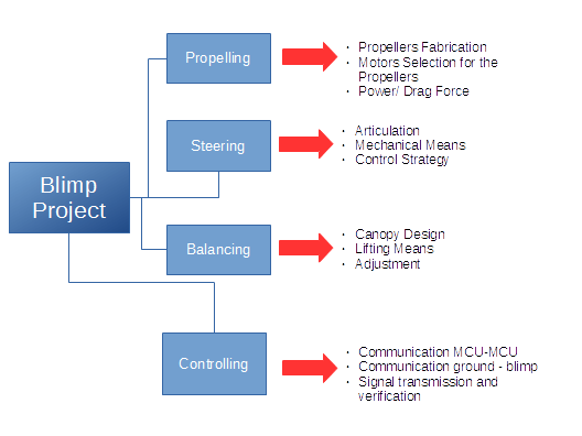
Project DevelopmentSo much done, so little room to get through it. I'll go and try to cover as much ground as possible, in the most Synthetic way Possible, including the files of the work in progress, but first, a little mind-clearing is in order, I made a breakdown structure for the project as it is intended to work, this meaning there are four aspects to solve in order to get the project done: The propelling, Steering, Balancing, and Controlling. To consider the project as working would require to tackle these issues, or, put in other way, to answer the following questions: PropellingThe
airship can move on its own? SteeringIs there a proper mechanism to steer the airship?Can it be reliably controlled? BalancingCan the airship be properly balanced?Can it keep itself balanced regardless of the motion? ControllingCan the airship be controlled?Is that control Reliable? To add more detail, I made a Breakdown structur for the project, including these general aspects and a few more detailed items which can be seen below.
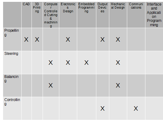
So, in order to properly work on the project is necessary to work through these issues, However, the items in the list may not completely be part of a single domain in the course, so another breakdown is in order, the one that connects the main items talked about, for this I made a breakdown matrix, including the areas to be covered comparing them to the items of the course, this can be seen below.
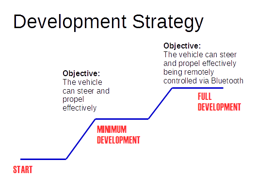
However, after all this clarification effort, still lies a pending issue: the development strategy, since aiming for the whole project done is a recipe for failure, a little order is needed to know how far does is needed to go. If not, the project could very well end up looking like:
After realizing this, I quickly realized that for this project, there would be needed al least two scenarios, the first, where a minimal level of functionality is acheived and the second, including the full capabilities desired, as can be seen in the image below:
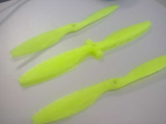
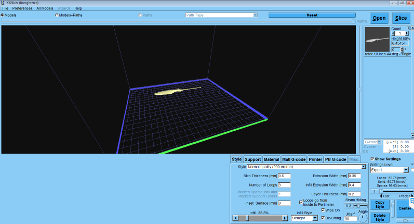
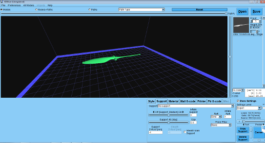
The current aim is towards minimum functionality, though some steps taken in the direction to full development have been done, I will talk about what has been done so far. Additional information including Bill of Materials and cost, will be included in the Final Project Documentation Page. Propelling - Making the propellersthe Propellers for the Airship were 3D Printed in The Felix 3.0 3D Printer we have available at ESAN. I scaled down The Jens Dyvik hexacopter propeller designed and it fitted the shafts for the small DC Motors I have purchased. The shape, due to its curved form had to be 3D Printed using raft and Supports. For this particular case, I used 0.20mm layer height quality for printing, the supports that were printed had to be physically removed. In the photo below, the supports and raft can be seen in the center propeller.
To print these parts, a slightly different workflow was followed, this time the slicing was done in a separate app, KISSlicer. Printing configuration aspects, such as raft, supports, and quality, had to be set up here.
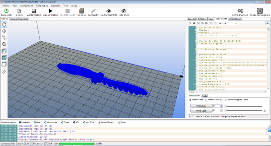
The Slicer generates the necessary GCODE to process and print the part
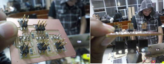
Canopy Design and balancingI have gone in detail in this matter in the Mechanical Design Section. Electronics for Steering and ControllingThis item item is the one that has taken the longest and still presents some challenges.The project for the blimp implies, electronically speaking, using MCUs to control the steering and propulsion for the blimps, this is being done by connecting and Arduino and Fabduino and make each of them control a part of the motions in turn.
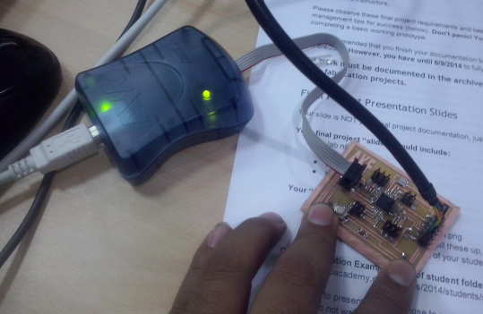
The second stage for further development includes adding a Bluetooth controller to the mix in order to direct the motions for the blimp from an Android App.
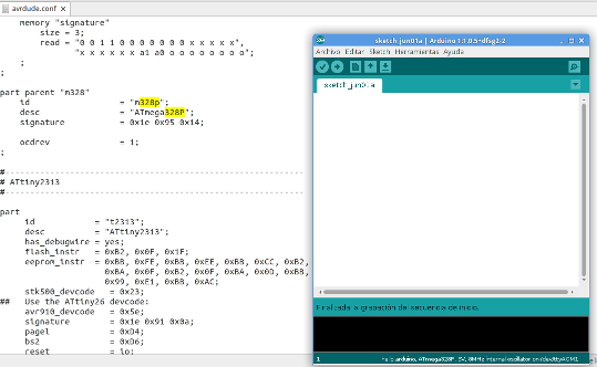
To achieve this, I remade a Fabuino since the one I had made was damaged. Stuffing and programming it was pretty straightforward, with the only exception that for this particular board I was using an Atmega 328 instead of the usual Atmega 328P, this meaning that and adjustment had to be made in theavrdude.conf in order to get to burn the Arduino bootloader in the MCU.
After this, it was time to integrate the fabduino with the mobile sections of the project, and since our souce of energy for the project was just standard 9V batteries, I used the voltage regulators available in the lab to make a board to connect the devices to it, given that the fabduino and servos work at 5V. This is a previous design for this in the Output Devices Assignment.
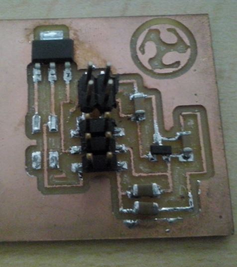
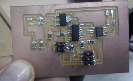
Starting from this design, I added a A4953 Driver for the DC Motors and a 3.3 V supply for the bluetooth module, this was done in two iterations, the first was using a 3.3V Voltage Regulator from the fab Inventory, the board made can be seen below, without the supply pins that got removed while testing it.
Testing would yield no satisfying results, so finally, I opted for a Zener Diode to get the job done this approach would be added to the board including an A4953 Motor driver for the DCs..
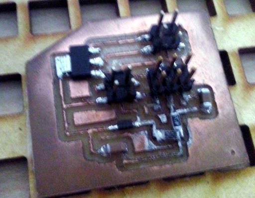
This would not work because of poor soldering, after several tries using the logic indicated in the datasheet. I tried to extend the concept, designing a board similar to the Hello.H-bridge example board, just adding a 2x2 pin header to connect the signal from the Tiny 44 from the Fabduino, it would not work either.
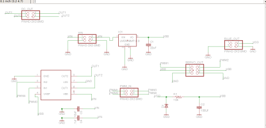
This as due to the fact that the A4953 footprint was not accurate (it did not include the space for soldering the bottom pad to the ground, I settled for another design, including the Zener Diode in order to control just the servo and power the Bluetooth Module:
However, as I tested the Zener Output, it did not get anywhere near the needed 3.3 Volts for the Bluetooth mode, after checking and after some suggestions, Francisco told me that maybe adding resistors to the power line, the otuput would improve, having no time to remake the board, I soldered the resistors on the fly, it was very tricky and difficult, but it was done nonetheless. And I got really 3.3V ready for use!
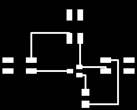
This, however, left out the DC Motors I intended to use for the propellers, after trying to make them work with the fabduino and the servo at the same time without success, a friend suggested a transistor should be used in order to get the signal from the fabduino to get to the motors. I found a P-channel MOSFET (Fairchild NDS 356 A) in the inventory and made a testing board for it:
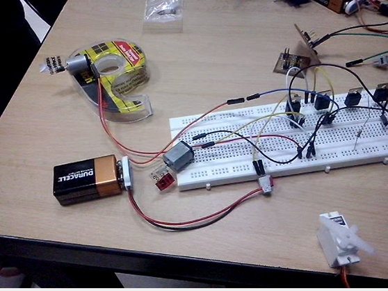
This, however, would not work either, and, after Francisco's Suggestion, I tried breadbording with an Arduino Board, the DC motors and a few IRF 730 N-channel MOSFETs and the system worked fine.
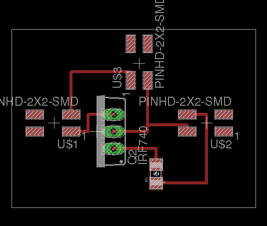
From this, I designed another board to include these MOSFETs to feed the motors.
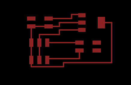
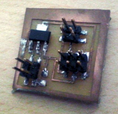
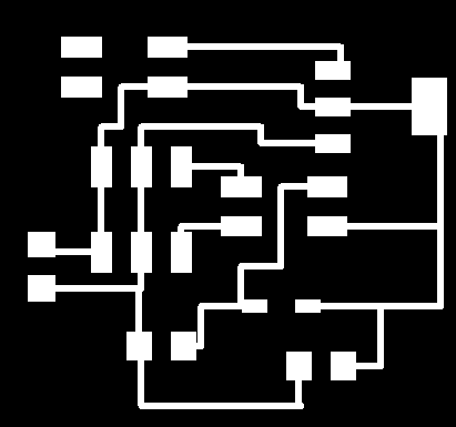
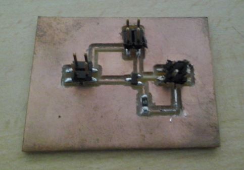
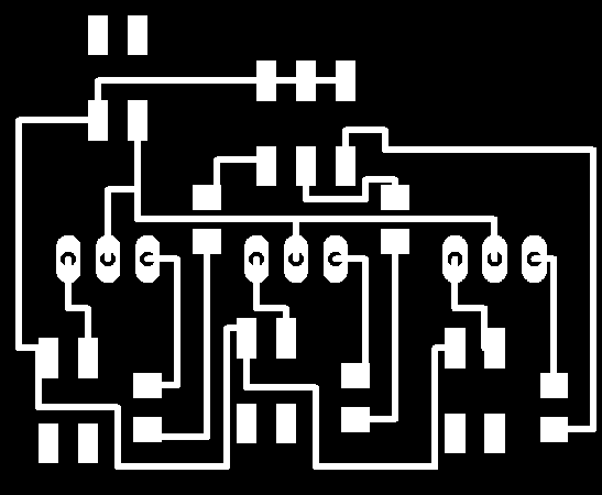
But, since I needed two or three motors working at the same time, I extended the design concept and made a Distributor board:
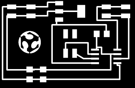
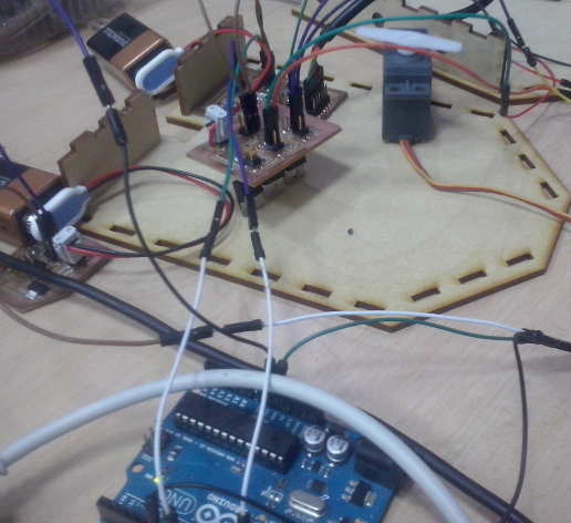
Some traces from the MOSFETs had to be jumped on using 0 ohm reistors since the trace that would transmit the signal from the MCUs crossed over the VCC path. After milling and stuffing the board it was ready for testing.
The testing was succesful, though one of the power MOSFETS seemed to be not so well soldered to the board.
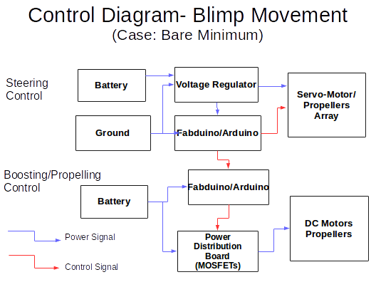
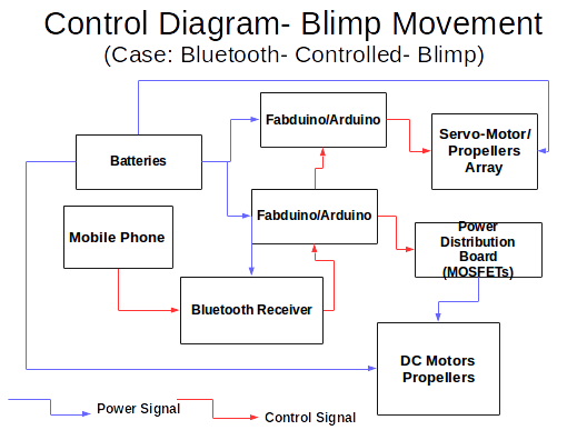
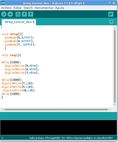
After this, The project was ready for final assembly. Programming (Steering, Propelling and Controlling)The entire Microcontroller Programmig was done using the Arduino IDE. I worked on the two scenarios described by the control diagrams at the beginning of the page. For the first case, it was assumed that the Fabduino would control the DC Motors while an Arduino Uno would be used to work the Servos. The code for both MCUs is quite straightforward.
in the first case, it sends an "ON" signal for the DCs and the other Arduino.
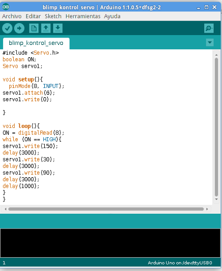
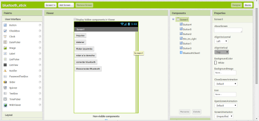
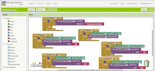
The program above controls the servomotor, it reads a pin (receiving a signal from the other Fabduino) and while this signal is read HIGH (or ON) will activate the servo with a given sequence of commands, this enables the servo to steer the airship. In order to integrate this scheme with the mobile/bluetooth controller, an AppInventor mobile app was developed for such purpose, this will send bytes over the bluetooth signal that would be read by the MCU via serial Port.
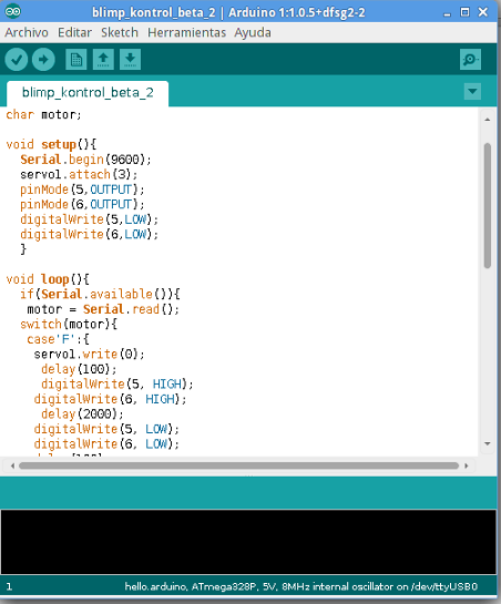
In this case the MCU reads the serial port, and depending on the byte (or char) received, it will execute actions combining steering and propelling in order the lead the airship in a given direction, in this case the program has set three options via the switch()selector in the Arduino code: The chars to be received are "R","L" and "F" for Right, Left and forward, respectively, in each case the servo sets itself at a given angle and turns the propellers on to get the airship to move. The source code for the programs used for the Arduino IDE can be found here, here and here. |