| Index About Me |
Output Devices AssignmentThis assignment took a very long time to get done, because of many reasons, but, in the end, a few valuable lessons were learned.For this particular assignment, it was about controlling a device, so, after a little brainstorming, I got to a preliminary workflow for the assignment 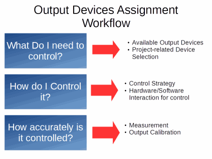
First, it was
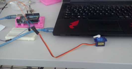
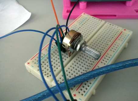
just about writing some basic code in order to make the servo
work, after that was done, I added a potentiometer to the mix.
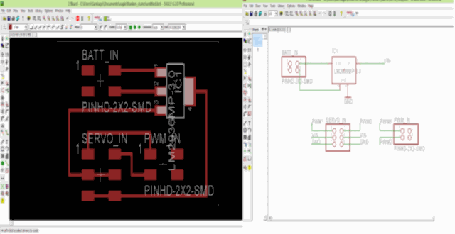
 Being done with that, it was time for the next step, this being making the example board to control the servos, and learn how does it work in order to replicate/improve/simplify it. Being experienced in milling and assembling boards at this point, and it all seemed to be fine in the beginning, as the board got to be programmed, but as I plugged in the servos and the battery,nothing occurred. I used a multimeter to track the voltages in the board in order to detect any possible failure and I found that the VCC trace that was supposed to get from the MCU power supply to the ISP jumper was broken, so no energy was getting there and being relayed to the jumpers the servos were to be connected to, so I soldered a wire bridge to solve this problem, and, as I put the multimeter to work, I had 5V in the servo pins, and, even though the program was already loaded, it was no use. The servos would not move. The board would have to be remade. 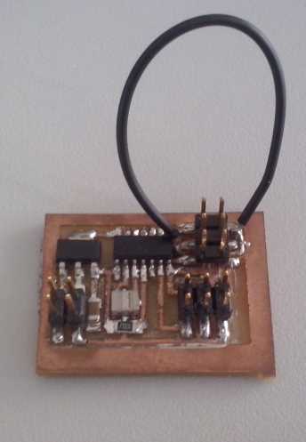 So, after remaking the
board and stuffing it, the program worked and the servos worked without
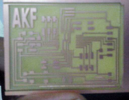
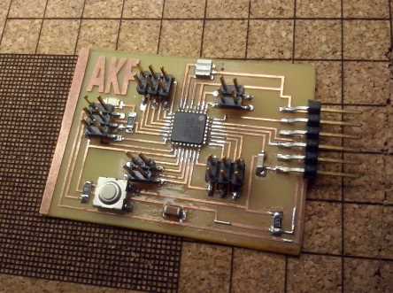
problem as well: Since the objective of the assignment was to make or design your own board, I decided to start from the Hello servo board and convert it into a relay board in order to use an arduino. For the Arduino/Fabduino Board I used the design from Anna Kaziunas in order to have access to as many pins as possible, just in case..
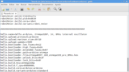
We had 20 Mhz resonators in the fablab, so I burn the bootloader using the boards.txt file from Neil's HelloFabduino Board. First, I used the AVR ISP in the lab to test the connections.
After burning the bootloader, It was time for some testing. With the Fabduino done, it was time for designing a new board, in order to control the servos with the Fabduino, this was most simply done by starting from the Hello.Servo example board and removing the Tiny44 and the Resonator, this way I had the power supply for the servos (5V) and the control signal will be coming from the Fabduino. The board design was straightforward, building from the electronics design assignment. The most difficult part was finding the appropriate footprint for the 5V voltage regulator, finally, I could find one that suited perfectly. Then it was just ready for millling.
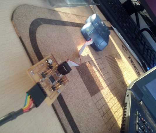
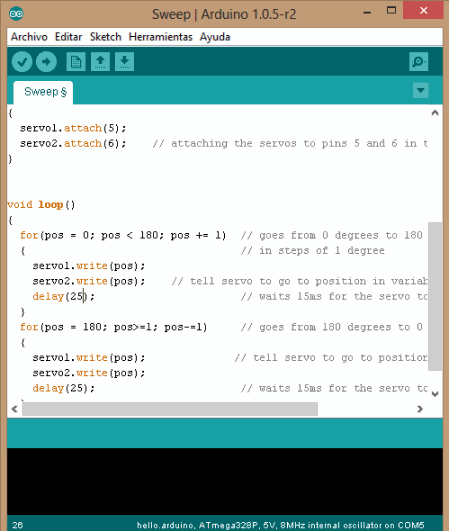
After designing and milling the board, it was time to put it to work. For testing I used a variation in the Arduino example code cases: "Sweep".
There are two details worth noticing here are the Servo.attach() statements, to get the servo to work from a control signal coming from such pins and the for() statement to make the servo "sweep" from 0 to 180 degrees and back. Since I am using a single variable to control both servos, they move in unison. However, that can be easily changed in the code. Finally, a video I took from the System at work: Conclusions?Electronic Design can be daunting, but it is not that much when you try it for real. Second, Eagle has certain limitations when it comes to board design, specially when rotating objects in the board, not as helpful as it might be thought. Third, a capacitor in parallel with the Voltage regulator seemed a bad idea when I designed, but in retrospect, not so bad idea. Fourth,
as previously stated, take into account Hofstadter's law into
assignment planning, it -painfully- works. |