| Index About Me |
Mechanical Design AssignmentThis assignment was very important facing the final project design, because, as its name says, it deals with the mechanical aspects of the project. I made this first approach to a workflow before starting: 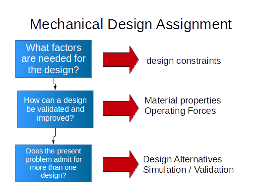 For my final project, there are a number of definite constraints that have to be addressed in order to succesfully get the airship to move. These are the following:
So, I proceeded
to tackle these issues for the final project, first the Frame design.
The objective was to create a frame light enough to be lifted by an
Array of Helium Baloons and be able to glide autonomously or via an
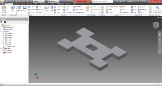
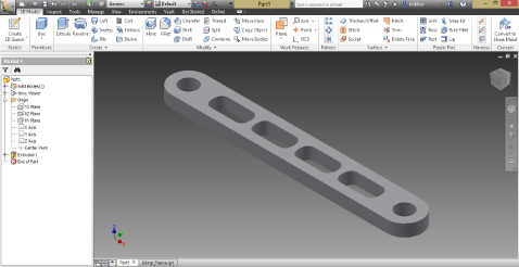
external control device. The first idea was to leave enough room in the
middle so a camera could be set there. This first approach was designed
in inventor:
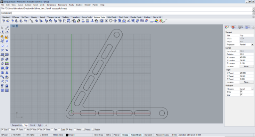
As the Final
presentation Day approached I started to work through this idea, then
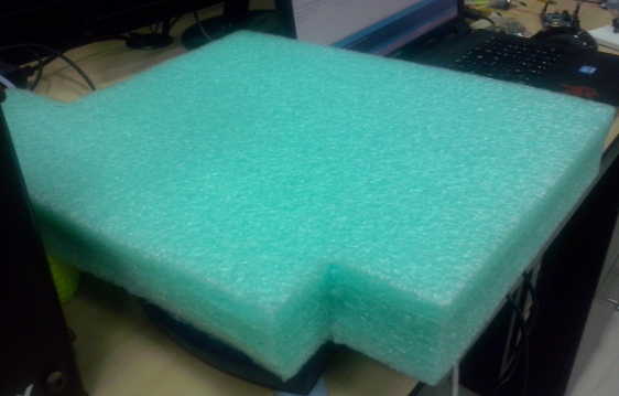
the camera was out of the way and a lighter design could be made, this
time, took a direct approach and cut the shape from foam. This frame
designed was shown in the final presentation day.
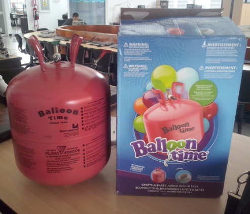
The idea behind the project was to use Helium gas to elevate the frame/canopy containing the electronics and propellers. I sourced locally a canister of Helium por party baloons as well as fifty baloons to lift the set.
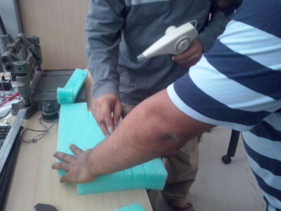
The initial tests with the Helium indicated that each baloon could lift around 5 grams of weight, so to lift the whole canopy including electronics and motors (140g) we would neer between 25-30 baloons to get the job done. To fabricate the frame, We started from a spare foam
block and cut it using a heat gun-heated cutter we had at the lab.
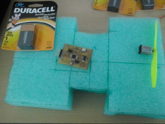
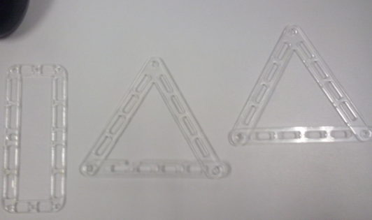
After making the frame, it was time to cut the space for the moving parts, being specific, the steering servomotor, but, in order to get the servomotor to steer effectively, I needed to design a simple mechanism to work with the servomotor in order to carry thre DC motors and steer the airship, the simplest way this could be done is by designing a piece that could press-fit the servomotor, for this, I used inventor and cut it using the laser cutter, the basic design is just an extension arm for the servomotor.
Widening this concept,
I duplicated the arm and rotated it, creating a sort of incomplete
triangular piece, this would help me better steer the airship:
Since "closing" the triangle would need and additional piece and fixating elements such as bolts or screws, I went on to design a single piece to steet the airship. this one would press-fit with the servo and have the DC motors attached in the other side.
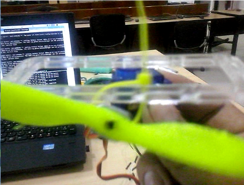
The Assembly was tested attaching one of the DC Motors to the piece using a cord and a small servo on the other end.
In the next image the evolution of the design can be seen, including a more detailed take on the final piece:
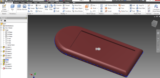
After testing the first blimp design in the final presentation day, it was made certain that some changes needed to be made for it to work successfully, for instance, the first canopy area was to large, making it harder to balance, so a new canopy design was in order, for this I went two ways, one, assuming that the project could behave in a way similar to a Hovercraft over water, and taking this into account I designed a new canopy:
This meaning that
the project's hardware would be placed upon the "platform" made in the
depressed zone. I exported the design and made an attempt to mill it in
the shopbot using Partworks 3D. At the time, the Shopbot had 12mm
Plywood on it, so I had to scale the model to mill it, the result was
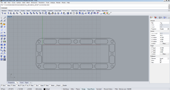
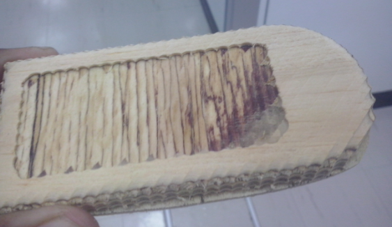
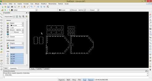
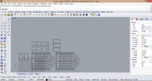
not very functional, So I had to make something else. I Used Rhinoceros for Modelling a new press-fit canopy, here is the DXF exported prior to laser cutting, the cut model can be seen in a photo in the Project Development page:
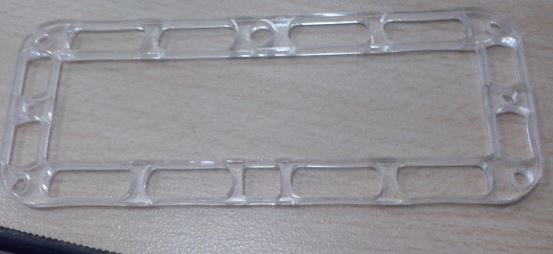
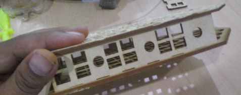
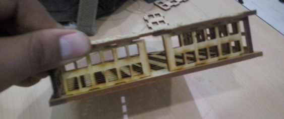
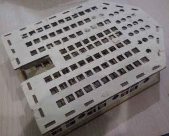
After cutting, it was cleat the the enclosure built was too bulky and heavy for the airship, so, in order to light the parts I introduced an array of geometrical forms to be cut with the model.
The assembled canopy model can be seen assembled in the following pictures.
the design files for this assignment can be found here Conclusions?Design is everything in this assignment. Second, it's always about what needs to be designed Third, sometimes, making things really simple can be daunting. Keep that in mind Fourth,
as previously stated, take into account Hofstadter's law into
assignment planning, it -painfully- works. |