Week 6: Electronics Design
This week's assignment is to redraw the echo hello-world board and add at least a button and LED. In order to complete this task, I followed the steps provided in the Providence Lab AS220 tutorial.
To start, download the Hello Echo schematic and board files. After extracting the zip folder, place a copy of the folder into your Eagle folder.
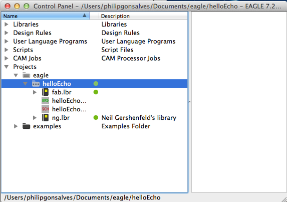
Open Eagle, the helloEcho folder should be visable under "Projects" in the Control Panel. Make sure the little dot to the right of the libraries are green. If they are grey right click on it and check "use" to turn it green.
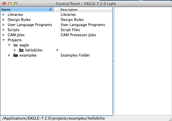
Right click on the grey circle and select "use" from the menu. The circle should turn green
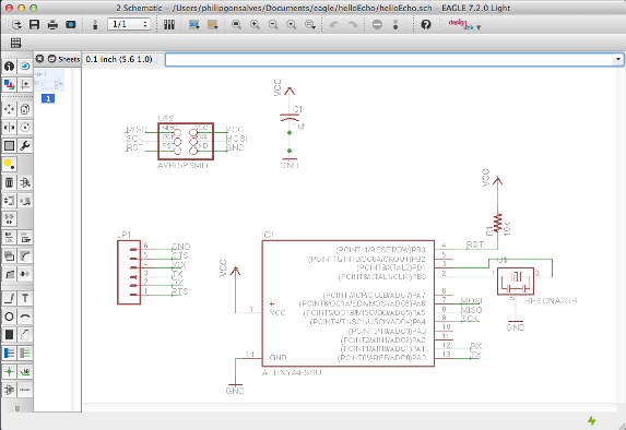
Open up the schematic for "Hello Echo", it should look like:
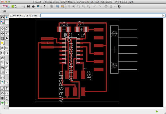
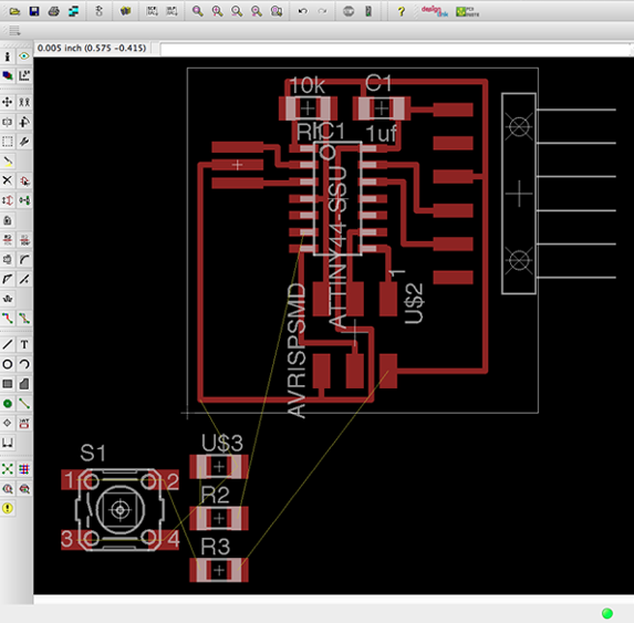
Open up the board layout for "Hello Echo", it should look like:
Eagle has a lot of built in libraries of components but there are several specific libraries that you will need for this class. Download the Libraries. After downloading them - unzip them and move them to the appropriate place for your operating system (/Applications/EAGLE/lbr/). Go to the top toolbar and select the "Library" menu, select "use"
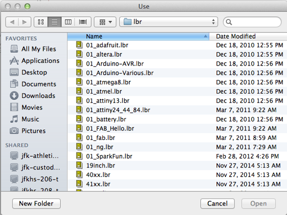
Select all the libraries with 01 in front a click "open". All of the libraries should now be available and at the top of the list.
Now the libraries are loaded and available, now its time to design the board. Eagle has two windows that you can use simultaneously to design a board, the Schematic (.sch) with components and the Board Layout (.brd) for the actual board that we mill.
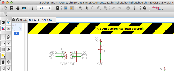
Don't close the layout and not the schematic (or vice versa) - you need to keep both open all the time. Closing one view while the other view is open (and making edits) will break the link between the two. Eagle will warn you if this happens:
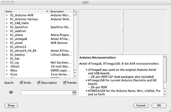
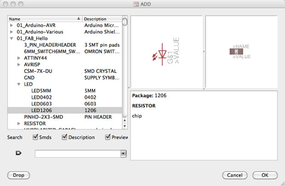
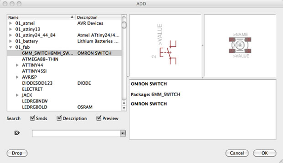
Now we have to edit the schematic to account for the new components we will be adding to the board. Open up the add menu in Eagle, select the appropriate component, click "OK" and then click on the schematic to place the component. You will need to add:
- RES 10K
- BUTTON
- GROUND
- VCC
- LED
- RES 499
Add LED (You will need 1 - in the FAB_Hello library)
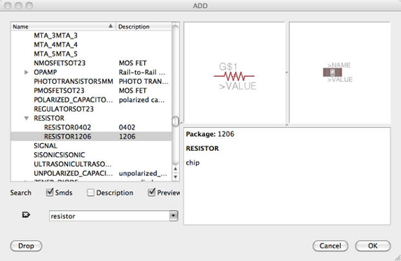
Add Resistors (You will need 2 - in the ng library)
Add Button (You will need 1 - in the 01_fab library)
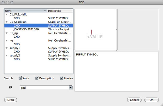
Add Grounds
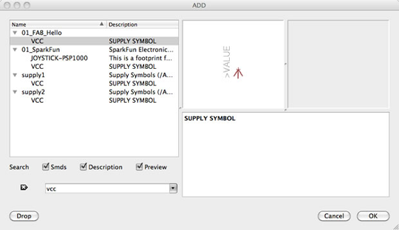
Add VCC (connection to power)
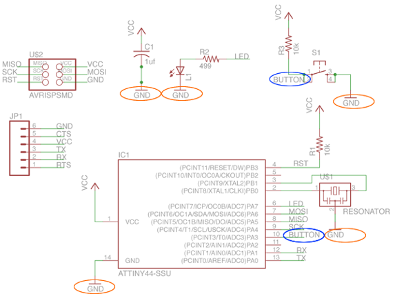
Now that the new components have been added and placed on the schematic now its time to connect them. You can connect the components with a wire or "net" which make connections obvious at first, but can get messy quickly as nets cross over each other. You can avoid this mess by naming the "nets" attached to components that need to be connected by naming them with the same name. Eagle will ask you if you want them to be connected, say yes. After you name the component - label it so the name appears in the diagram.
For example in the schematic below, all components named GND are connected to a common ground point. The button is connected to a net on the button component and a pin on the microcontroller:
Now that the components have all been added, connected and labeled, now we need to route the traces on the board.
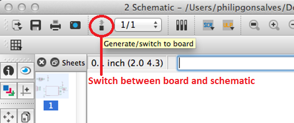
Switch to the board view (top menu > file > switch to board). The board view will open up with all the newly added components jumbled up in a corner with yellow unrouted traces attached.
Use "move" to move each individual component around. Use "route" to route each trace. The wire will turn red as you route it into place. After you route wires, you can use the "move" tool to move them around as lines.
There is a autorouter feature, which automatically routes all the components for you and is good for making a general layout, but you will still probably have to edit the traces manually to even when choosing this option. (top menu > tools > auto)
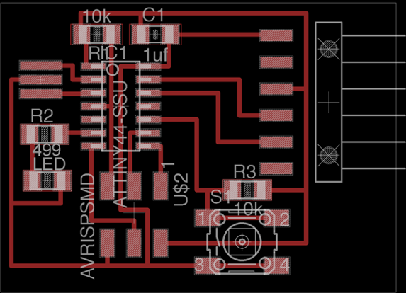
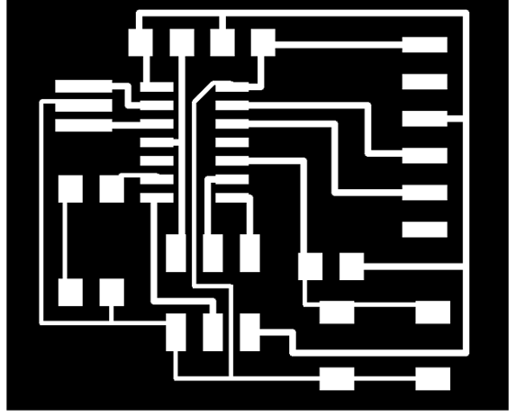
Route all the traces until it looks something similar to the diagram below. It doesnt have to look exactly the same, there is more than one way to route the traces. Just use this as a guide.
Now that the new board has been designed, we need to export the design to be used with Modela to mill the traces and cut out the board. To prep board for milling:
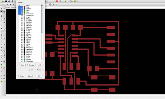
in the top menu > layers menu > select only the top (traces only)
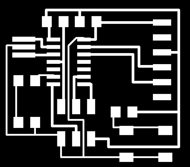
After the top layer is the only layer showing, export the file as a .png (file > export > image). The settings should be Monochrome and 500 DPI - selecting monochrome will export a image with white traces. Make sure the color mode is set to greyscale (image > mode > greyscale). Then go back to the layers menu and only select the Dimension layer. Then follow the same steps for exporting the file as a png to create the file used for milling the outside of the board.
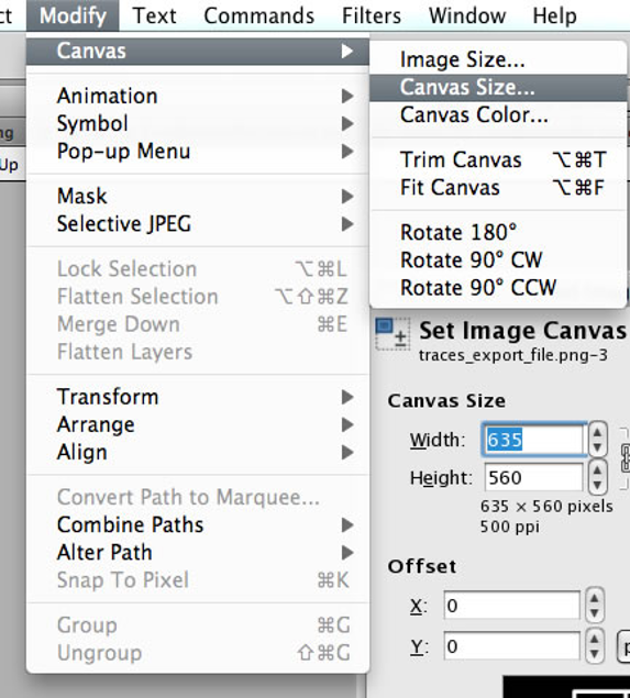
To edit the Board Files/Create traces and mill-out files use Gimp. Open up the board traces .png in Gimp. Crop the file if necessary. Go to the "Modify" menu > Canvas > Canvas Size
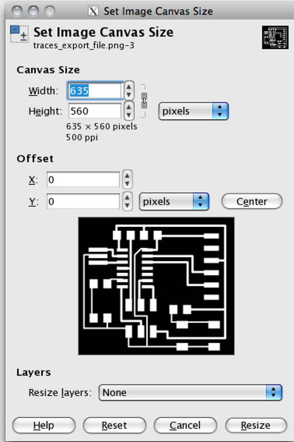
To create the white boarder around the image, add 20px to the width (make sure the proportions are linked). After adding 20px, hit the "center" button to center the image on the resized canvas. Flatten the image (image > flatten image). You will now have a 20px white boarder around the board traces image. Save the file and you are ready to mill traces on the Roland Modela.
To create the interior png, start with the traces png that you have already created. Save the file with a different name. Use the bucket/fill tool to fill in all the white spaces, except the boarder, leaving the white boarder around the image alone. Once all the traces are filled in, save the file and this can now be used on the Roland Modela to cut out the board.

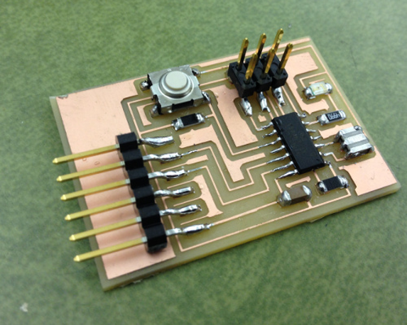
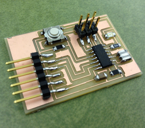
Once the traces have been milled and the board cut out, populate the board with the appropriate components and this week's assignment is done.
Check out Week 8: Embedded Programming to follow how to program the LED + button board you just created.