
Week 15: Networking and Communications
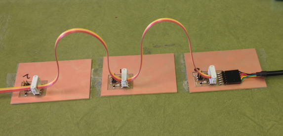
For this week's assignment, I am building a wired serial network using the hello.bridge board and two hello.node boards.
Download all the necessary files including the C file, the makefile, hello.bus.45.bridge (traces, interior) & the hello.bus.45.node (traces, interior) Place the downloads in a folder on the desktop labeled hello.bus.
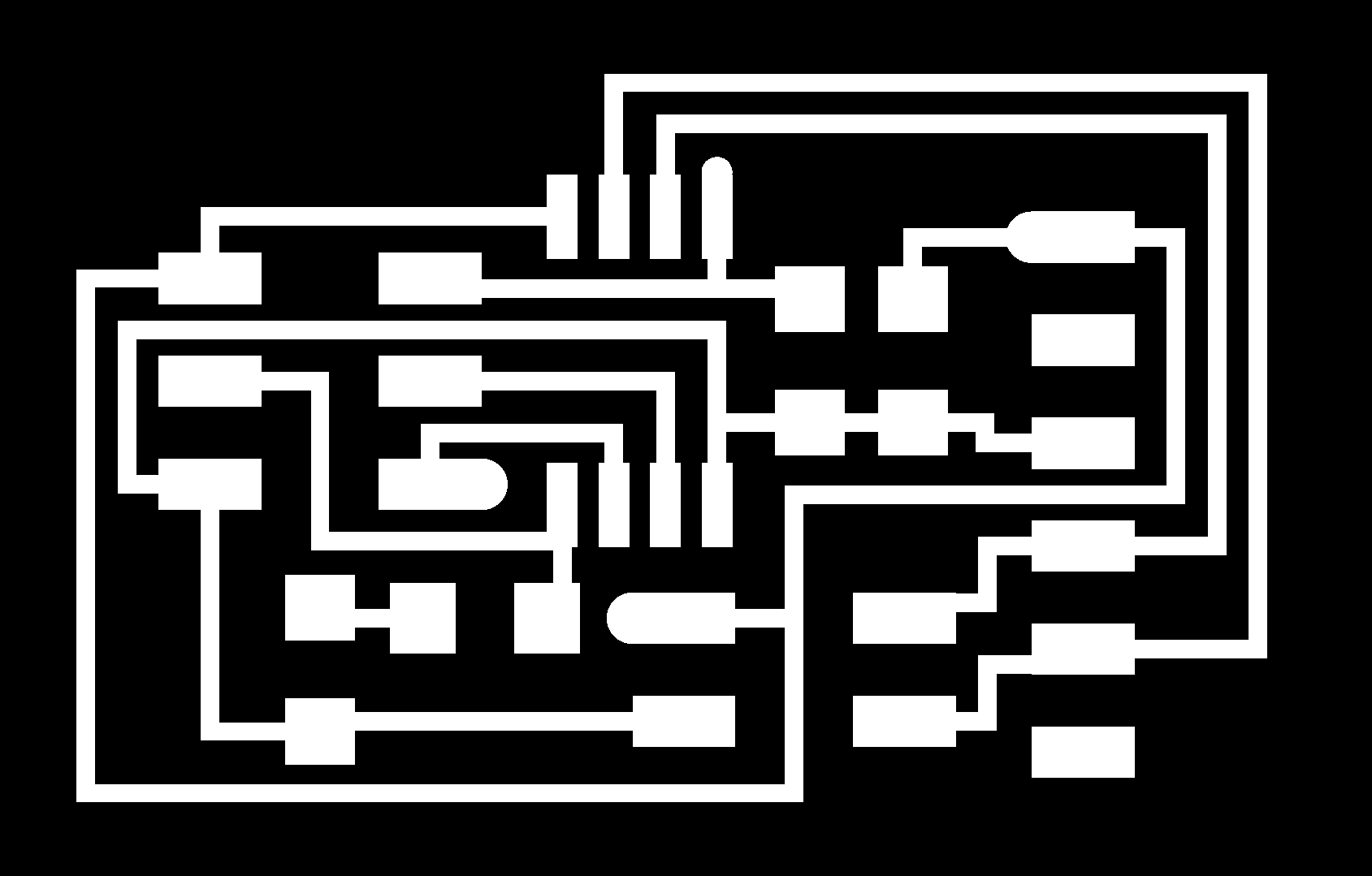
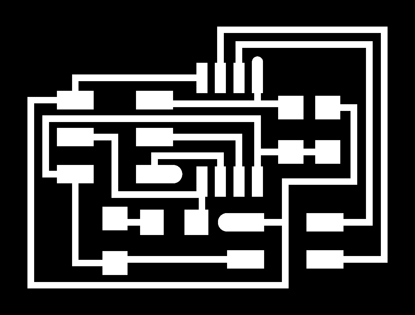
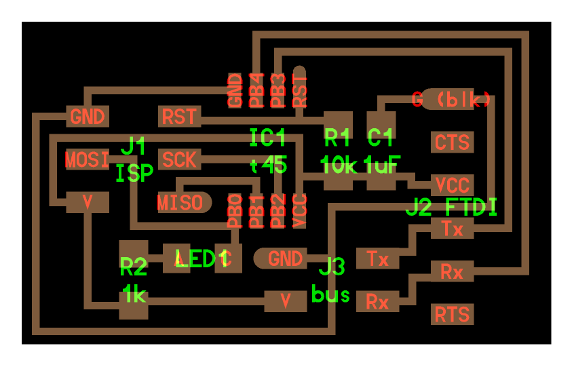
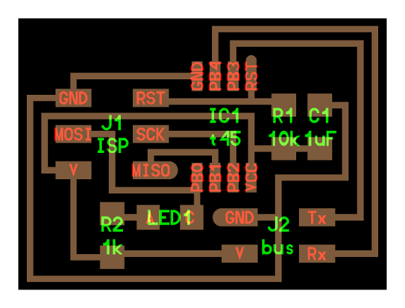
Using the Roland Modela, cut one hello.bus.45.bridge board and two hello.bus.45.node boards. Follow the steps covered in Week 4: Electronics Production to mill the traces and cut out the boards. After milling and cutting out the 3 boards, populate them according to the following schematic
Bridge Board:
Node Board:
Materials needed:
Bridge Board
(1) ATTINY 45
(1) 2x3 CONNECTOR
(1) 2x2 CONNECTOR
(1) RES 1K
(1) LED
(1) RES 10K
(1) CAP 1UF
(1) FDTI 6 PIN CONNECTOR
Node Boards
(2) ATTINY 45
(2) 2x3 CONNECTOR
(2) 2x2 CONNECTOR
(2) RES 1K
(2) LED
(2) RES 10K
(2) CAP 1UF
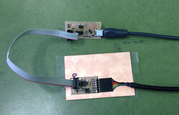
After populating the boards, connect the bridge board to the usbtiny, and connect the FDTI cable to the bridge board.
Open the terminal window and navigate to the hello.bus folder on your desktop where the downloaded files are by typing in the following commands:
cd
cd desktop
cd hello.bus
Once you've navigated to the folder, compile the c code by typing in the following command:
sudo make -f hello.bus.45.make
Once the c code has been compiled, flash the board:
avrdude -p t45 -c usbtiny -U flash:w:hello.bus.45.c.hex
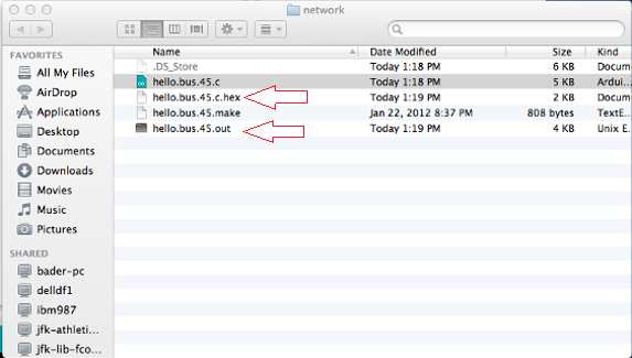
Once the c code has been compiled and the board has been flashed, delete the .out and the .hex file from the folder. You will need to repeat this step for each new board you program.
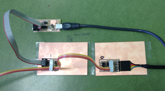
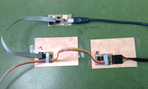
Once the files have been deleted, connect the usbtiny to the first node board. Connect the bridge board and the node board with a cable, with the FTDI cable still connected to the bridge board.
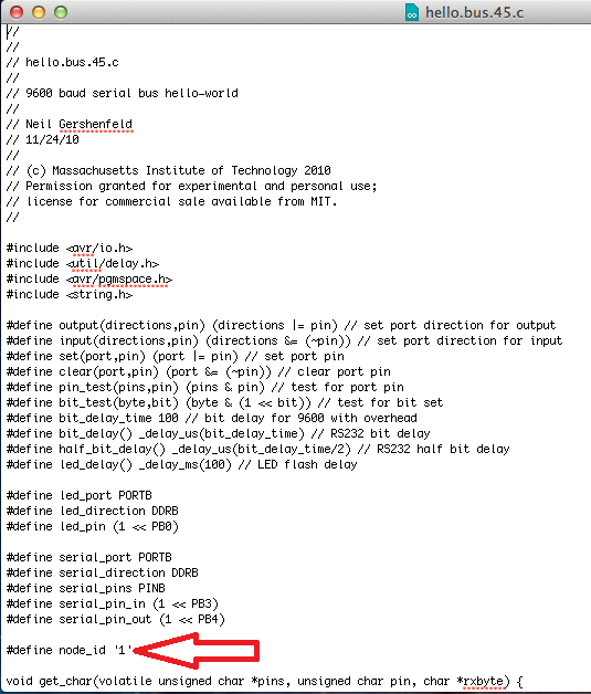
Open up the hello.bus.45.c file in textedit and change the node id from '0' to '1'. Giving the new board a seperate node id.
Once the node_id has been changed, save the file and repeat the steps for compiling the c code and flashing the board:
compiling c code:
sudo make -f hello.bus.45.make
flashing the board:
avrdude -p t45 -c usbtiny -U flash:w:hello.bus.45.c.hex
Remove the first node board and connect the second node. Repeat the process of deleting the .out and .hex files from the hello.bus folder. Open the c code in textedit and change the node_id from '1' to '2'
Repeat steps for compiling the c code and flashing the microcontroller.
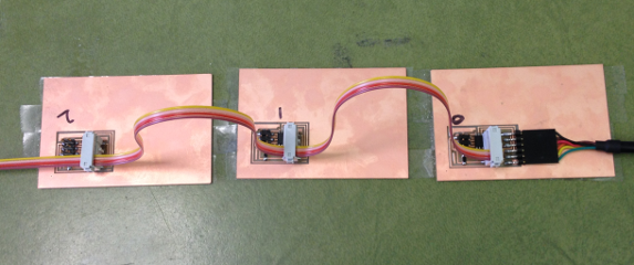
Once the last node board has been flashed, disconnect the usbtiny. Connect the FDTI cable to the bridge board and connect all three boards together using a cable.
To check if the programming was successful open up Arduino and under Tools select Serial Port, making sure the correct FTDI port is selected. Under Tools select Serial Monitor, and once the window pops up make sure the field in the bottom right corner is set to 9600 baud.
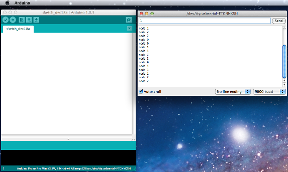
Type in a 0,1, or 2 to see the boards respond. The number board you enter will blink twice while all boards connected will blink only once, as well as a response in the serial port window of the node you entered. If blinking happens too fast you can adjust the delay time in the c file.